2010 Hyundai H-100 Truck stop start
[x] Cancel search: stop startPage 155 of 207

5
VEHICLE MAINTENANCE REQUIREMENTS
9
!
EXPLANATION OF SCHEDULED MAINTENANCE ITEMS
F060M01A-AAT
o Engine Oil and Filter
The engine oil and filter should be
changed at those intervals specified in the maintenance schedule. If the ve- hicle is being driven in severe condi-tions, more frequent oil and filter changes are required.
F060N01HR-GAT
o Valve Clearances
An incorrect valve clearance will not
only result in rough engine operation, but will also cause excessive noiseand reduced engine output.
Inspect valve clearance and adjust as
required while the engine is hot.
See page 9-4 for the valve clearance
description. F060D01TB-GAT
o Fuel Lines, Fuel Hoses and
Connections
Check the fuel lines, fuel hoses and
connections for leakage and damage. Have a trained technician replace any damaged or leaking parts immediately. F060C01A-AAT
o Fuel Filter A clogged filter can limit the speed at which the vehicle may be driven, dam- age the emission system and cause hard starting. If an excessive amountof foreign matter accumulates in the fuel tank, the filter may require re- placement more frequently.After installing a new filter, run theengine for several minutes, and checkfor leaks at the connections. Fuel fil- ters should be installed by trained technicians.
WARNING:
Never work on injection system withengine running or within 30 sec- onds after shutting off engine. High pressure pump, rail, injectors andhigh pressure pipes are subject to high pressure even after the engine stopped. The fuel jet produced byfuel leaks may cause serious injury, if it touch the body. People using pacemakers should not move than30cm closer to the ECU or wiring harness within the engine room while engine is running, since thehigh currents in the Common Rail system produce considerable mag- netic fields.
Page 157 of 207

5
VEHICLE MAINTENANCE REQUIREMENTS
11
F070F01A-AAT
o Brake Hoses and Lines
Visually check for proper installation, chafing, cracks, deterioration and any leakage. Replace any deteriorated or damaged parts immediately. F070G02A-GAT
o Brake Fluid
Check brake fluid level in the brake fluid reservoir. The level should be between "MIN" and "MAX" marks on the side of the reservoir. Use only hydraulic brake fluid conforming to DOT3 or DOT 4.
F070L01A-AAT
o Suspension Mounting Bolts
Check the suspension connections for
looseness or damage. Retighten to thespecified torque. F070M01A-AAT
o Steering Gear Box, Linkage &
Boots/Lower arm Ball Joint
With the vehicle stopped and engine off, check for excessive free-play in the steering wheel. Check the linkage for bends or damage. Check the dustboots and ball joints for deterioration, cracks, or damage. Replace any dam- aged parts. F070N01A-AAT
o Power Steering Pump, Belt and Hoses
Check the power steering pump and hoses for leakage and damage. Re-place any damaged or leaking parts immediately. Inspect the power steer- ing belt for evidence of cuts, cracks,excessive wear, oiliness and proper tension. Replace or adjust it if neces- sary.
F070J01A-AAT
o Brake Pads, Calipers and
Rotors
Check the pads for excessive wear,
discs for run out and wear, and cali- pers for fluid leakage.
F070K01A-AAT
o Exhaust Pipe and Muffler
Visually inspect the exhaust pipes,
muffler and hangers for cracks, dete-rioration, or damage. Start the engine and listen carefully for any exhaustgas leakage. Tighten connections or replace parts as necessary.
F070H01A-AAT
o Rear Brake Drums/Linings
Parking Brake
Check the rear brake drums and lin-
ings for scoring, burning, leaking fluid, broken parts, and excessive wear. Inspect the parking brake system in- cluding the parking brake lever andcables. For detailed service proce- dures, refer to the Shop Manual.
Page 167 of 207

6
DO-IT-YOURSELF MAINTENANCE
9
!WARNING:
Be very careful when draining the engine oil as it may be hot enough to burn you!
4. When the oil has stopped draining, replace the drain plug using a new gasket and retighten by turning it clockwise.
Tightening torque : 3.5 ~ 4.5 kgf.m
5. Remove the oil filter by turning it counterclockwise with a oil filter wrench of the proper size. A certainamount of oil will come out when you remove the filter. So be sure to have your drain pan in place underneathit.
6. Install a new oil filter in accordance
with the instructions on the carton oron the filter itself. Do not over-tighten.
Tightening torque: 2.3 ~ 2.5 kgf.m Be sure that the mounting surfaceon the engine is clean and that theold gasket is removed completely. Lubricate the new gasket on the filter with clean engine oil beforeinstallation.!
7. Remove the engine oil level dipstick.
8. Refill the crankcase with the recom- mended engine oil slowly. Refer to the specification in chapter 9 for engine oil capacity.
CAUTION:
Slowly pour the recommended oilby using a funnel. Do not overfill not to damage the engine.
9. Start the engine and check to be sure no oil is leaking from the drain plug or oil filter.
10. Shut off the engine and recheck the
oil level.
NOTE: Always dispose of used engine oil in an environmentally acceptable man-ner. It is suggested that it be placed in a sealed container and taken to a service station for reclamation. Donot pour the oil on the ground or put it into the household trash. WARNING:
Used motor oil may cause irritation or cancer of the skin if left in contact with the skin for prolonged periods of time. Wash your hands thoroughlywith soap and warm water as soon as possible after handling used oil.
!
Page 184 of 207

6 DO-IT-YOURSELF MAINTENANCE
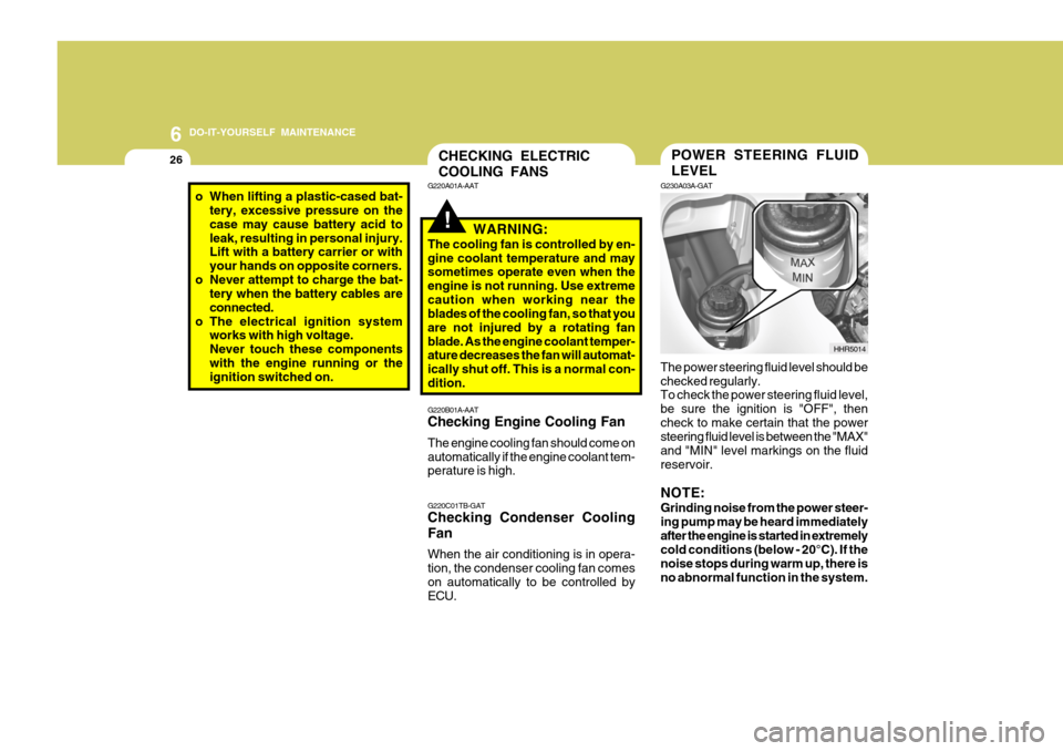
26POWER STEERING FLUID LEVEL
G230A03A-GAT The power steering fluid level should be checked regularly. To check the power steering fluid level, be sure the ignition is "OFF", thencheck to make certain that the power steering fluid level is between the "MAX" and "MIN" level markings on the fluidreservoir. NOTE: Grinding noise from the power steer- ing pump may be heard immediatelyafter the engine is started in extremely cold conditions (below - 20°C). If the noise stops during warm up, there isno abnormal function in the system. HHR5014CHECKING ELECTRIC COOLING FANS
!
G220B01A-AAT Checking Engine Cooling Fan The engine cooling fan should come on automatically if the engine coolant tem- perature is high. G220C01TB-GAT Checking Condenser Cooling Fan When the air conditioning is in opera- tion, the condenser cooling fan comeson automatically to be controlled by ECU.
G220A01A-AAT
WARNING:
The cooling fan is controlled by en- gine coolant temperature and may sometimes operate even when the engine is not running. Use extremecaution when working near the blades of the cooling fan, so that you are not injured by a rotating fanblade. As the engine coolant temper- ature decreases the fan will automat- ically shut off. This is a normal con-dition.
o When lifting a plastic-cased bat- tery, excessive pressure on the case may cause battery acid toleak, resulting in personal injury. Lift with a battery carrier or with your hands on opposite corners.
o Never attempt to charge the bat- tery when the battery cables areconnected.
o The electrical ignition system works with high voltage.Never touch these componentswith the engine running or the ignition switched on.
Page 196 of 207

6 DO-IT-YOURSELF MAINTENANCE
38
BATT
GLOW IGN
ECU
BATT
LAMP
COND ABS2
PTC1 ABS1
PTC2
BLWR PTC3
FFHS
GLOW ALT_S STOP
HORN
A/CON TCU
ECU1 ECU2
DESCRIPTION
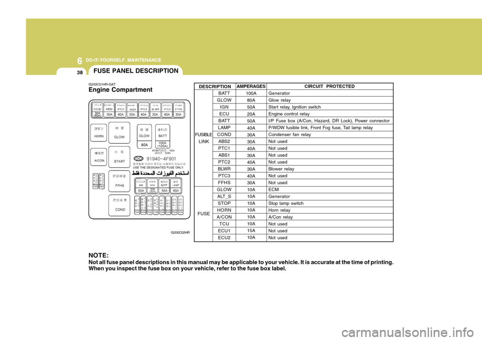
G200C01HR-GAT Engine Compartment
G200C02HR
NOTE:
Not all fuse panel descriptions in this manual may be applicable to your vehicle. It is accurate at the time of printing.
When you inspect the fuse box on your vehicle, refer to the fuse box label. AMPERAGES
100A80A 50A20A50A40A30A 30A40A 30A40A30A 40A 30A10A10A10A10A 10A 10A15A10A CIRCUIT PROTECTED
Generator Glow relay
Start relay, lgnition switchEngine control relay
I/P Fuse box (A/Con, Hazard, DR Lock), Power connector
P/WDW fusible link, Front Fog fuse, Tail lamp relayCondenser fan relayNot usedNot usedNot usedNot usedBlower relayNot usedNot usedECMGeneratorStop lamp switchHorn relayA/Con relayNot usedNot usedNot used
FUSIBLE LINK
FUSE
FUSE PANEL DESCRIPTION
Page 201 of 207

7
EMISSION CONTROL SYSTEMS
3EGR SYSTEM
!
H020C01HR-GAT (If Installed) This system helps control oxides of nitrogen by recirculating a part of the exhaust gas into the engine, there by reducing cylinder combustion tem-perature.The EGR system helps reduce Nox(Oxides of Nitrogen) emission gas- ses.
WARNING:
o Use diesel only.
o Maintain the engine in good operating condition. Extremely high catalytic converter tempera-tures can result from improper operation of the electrical, igni- tion or electronic fuel injection.
o If your engine stalls, pings, or is hard to start, have your Hyundaidealer inspect and repair theproblem as soon as possible.
o Avoid driving with a very low
fuel level. Running out of diesel may cause the engine to stop and result in damage to the cata-lytic converter.
o Avoid idling the engine for peri- ods longer than 10 minutes.
o The vehicle should not be pushed or pulled to get started.This may cause the catalytic converter to overheat and cre- ate a fire hazard. o Do not touch the catalytic con-
verter or any other part of theexhaust system while the cata- lytic converter is hot. Shut off the engine, wait for at least onehour before touching the cata- lytic converter or any other part of the exhaust system.
o Remember that your Hyundai dealer is your best source ofassistance.
o Do not park, idle or drive your
vehicle over any combustible ma- terial such as grass, paper, leaves or rags. These materials mightcontact the hot catalytic converter and a fire might result.