Page 192 of 530
successfully accepted the frequency signal. The indica-
tor light will flash slowly and then rapidly when fully
trained.
If you unplugged the device for training, plug it back in
at this time.
Then proceed with Step 4 under “Programming
HomeLink�,” earlier in this section.
Security
It is advised to erase all channels before you sell or turn
in your vehicle.
To do this, press and hold the two outside buttons for
20 seconds until the red indicator flashes. Note that all
channels will be erased. Individual channels cannot be
erased.
The HomeLink�Universal Transceiver is disabled when
the Vehicle Security Alarm is active.
Troubleshooting Tips
If you are having trouble programming HomeLink �, here
are some of the most common solutions:
•Replace the battery in the original transmitter.
•Press the LEARN button on the Garage Door Opener
to complete the training for a Rolling Code.
•Did you unplug the device for training, and remember
to plug it back in?
If you have any problems, or require assistance, please
call toll-free 1–800–355–3515 or, on the Internet at
www.HomeLink.com for information or assistance.
General Information
This device complies with FCC rules Part 15 and Industry
Canada RSS-210. Operation is subject to the following
two conditions:
1. This device may not cause harmful interference.
3
UNDERSTANDING THE FEATURES OF YOUR VEHICLE 191
Page 196 of 530
with the sunroof open, adjust the sunroof opening to
minimize the buffeting or open any window.
Sunroof Maintenance
Use only a non-abrasive cleaner and a soft cloth to clean
the glass panel.
ELECTRICAL POWER OUTLETS — IF EQUIPPED
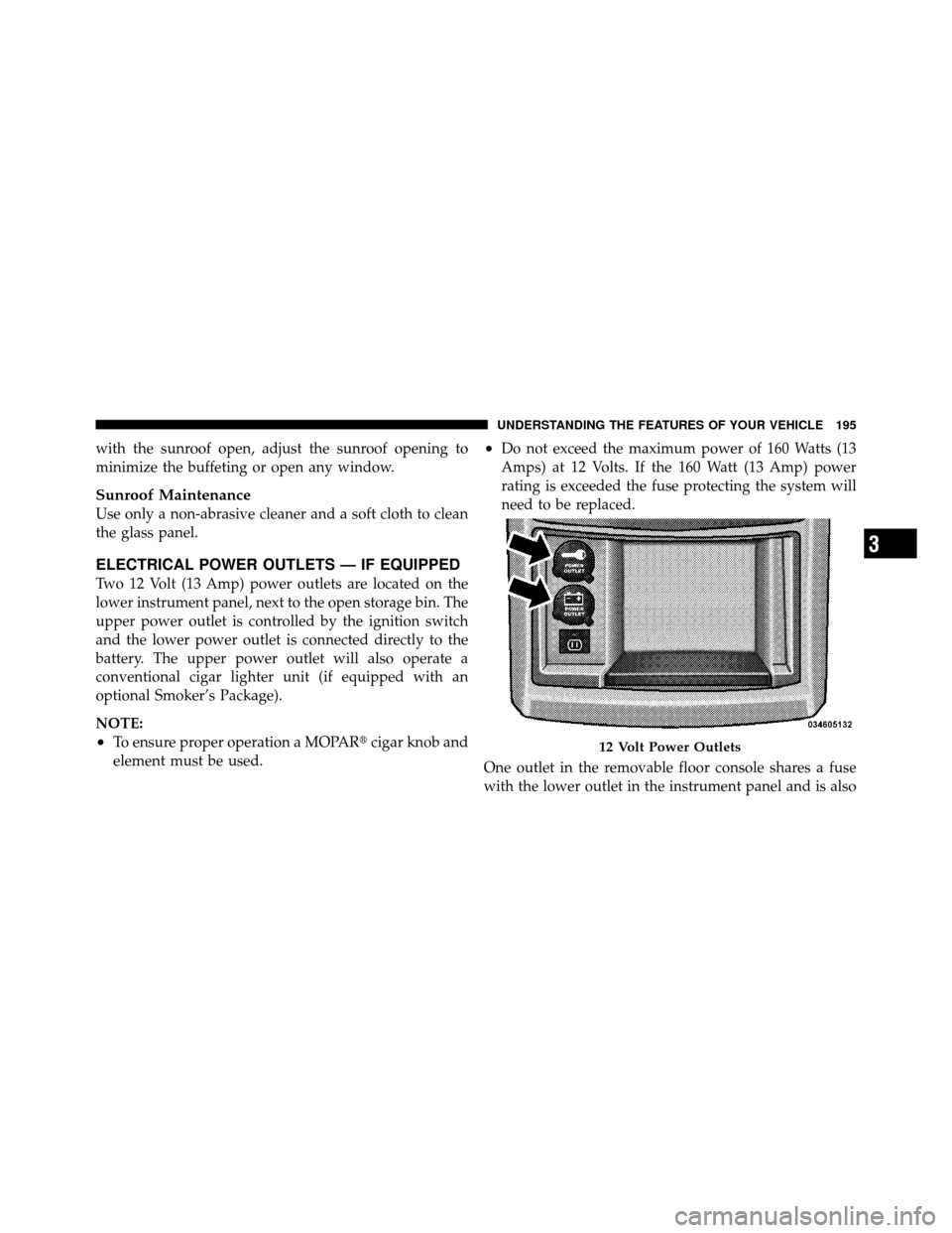
Two 12 Volt (13 Amp) power outlets are located on the
lower instrument panel, next to the open storage bin. The
upper power outlet is controlled by the ignition switch
and the lower power outlet is connected directly to the
battery. The upper power outlet will also operate a
conventional cigar lighter unit (if equipped with an
optional Smoker’s Package).
NOTE:
•To ensure proper operation a MOPAR�cigar knob and
element must be used.
•Do not exceed the maximum power of 160 Watts (13
Amps) at 12 Volts. If the 160 Watt (13 Amp) power
rating is exceeded the fuse protecting the system will
need to be replaced.
One outlet in the removable floor console shares a fuse
with the lower outlet in the instrument panel and is also
12 Volt Power Outlets
3
UNDERSTANDING THE FEATURES OF YOUR VEHICLE 195
Page 198 of 530
CAUTION! (Continued)
•Accessories that draw higher power (i.e., coolers,
vacuum cleaners, lights, etc.), will degrade the
battery even more quickly. Only use these inter-
mittently and with greater caution.
•After the use of high power draw accessories, or
long periods of the vehicle not being started (with
accessories still plugged in), the vehicle must be
driven a sufficient length of time to allow the
alternator to recharge the vehicle’s battery.
•Power outlets are designed for accessory plugs
only. Do not hang any type of accessory or acces-
sory bracket from the plug. Improper use of the
power outlet can cause damage.
POWER INVERTER — IF EQUIPPED
A 110 Volt, 150 Watt inverter outlet (if equipped) converts
DC current to AC current, and is located on the left rear
trim panel immediately behind the second row left
passenger seat. This outlet can power cellular phones,
electronics and other low power devices requiring power
up to 150 Watts. Certain high-end video games, such as
Playstation3 and XBox360 will exceed this power limit, as
will most power tools.
The power inverter is designed with built-in overload
protection. If the power rating of 150 Watts is exceeded,
the power inverter will automatically shut down. Once
the electrical device has been removed from the outlet the
inverter should automatically reset. If the power rating
exceeds approximately 170 Watts, the power inverter
may have to be reset manually. To reset the inverter
manually press the power inverter button OFF and ON.
3
UNDERSTANDING THE FEATURES OF YOUR VEHICLE 197
Page 209 of 530
Cargo Area Storage
The liftgate sill plate has a raised line with the statement
“Load To This Line”. This line indicates how far rearward
cargo can be placed without interfering with liftgate
closing.NOTE:
With all rear seats stowed or removed,4x8foot
sheets of building material will fit on the vehicle floor
with the liftgate closed. The front seats must be moved
slightly forward of the rearmost position.
CONSOLE FEATURES
There are two consoles available: Basic and Premium.
Basic Console
Basic Console features consist of the following:
•The basic console profile allows vehicle occupants to
easily pass through the first row to the second.
•Four cupholders accept up to extra large size beverage
cups or 20 oz (.6 L) plastic bottles. Cupholders are
dishwasher safe for cleaning.
•The cupholders are removable to access a large storage
bin.
Rear Cargo Area Loading Limit
208 UNDERSTANDING THE FEATURES OF YOUR VEHICLE
Page 210 of 530
•The basic console is removable from the vehicle for
additional floor space by removing the cap and clip at
the console base.
To Remove The Basic Floor Console
1. Remove the front anchor cup plug and clip.
2. Slide the console base forward while lifting slightly to
clear the rear load floor hook.
3. Remove the console.
To Reinstall The Basic Floor Console
1. Position the console at a slight angle (front slightly
higher than the rear).
2. Slide the console rearward into the floor bracket/
hook.
3. Align the console until the front anchor cup plug hole
is centered on the winch hole.4. Reinstall the clip first and then while pushing down-
ward on the console with slight pressure, reinstall the
cover plug.
5. Pull up on the console to be sure it is firmly latched.
WARNING!
In an accident, serious injury could result if the
removable floor console is not properly installed.
Always be sure the removable floor console is fully
latched.
Premium Console — If Equipped
The three-compartment console with sliding storage bin,
sliding upper tray with storage and large console storage
bin offers multiple configurations.
•Four cupholders with dishwasher safe liners for clean-
ing. The cupholders can accept plastic bottles, large
cups or mugs with handles.
3
UNDERSTANDING THE FEATURES OF YOUR VEHICLE 209
Page 214 of 530
3. Pull rearward to disengage from floor and remove
console.
To reinstall the console:
1. Position the console at a slight angle (rear slightly
higher than the front).
2. Slide the console forward into the floor bracket.
3. Rotate the rear of the console down until it is resting
on the floor bracket.
4. Push down on the rear of the console until it is seated
in the rear floor bracket.
5. Pull up on the console to be sure it is firmly latched.
WARNING!
In an accident, serious injury could result if the remov-
able floor console is not properly installed. Always be
sure the removable floor console is fully latched.
REAR WINDOW FEATURES
Rear Window Defroster
The rear window defroster button is located on the
climate control (Mode) knob. Press this button to
turn on the rear window defroster and the heated outside
mirrors (if equipped). An indicator in the button will
illuminate when the rear window defroster is on. The
rear window defroster automatically turns off after ap-
proximately 10 minutes. For an additional five minutes of
operation, press the button a second time.
NOTE:
•You can turn off the heated mirror feature at anytime
by pressing the rear window defroster switch a second
time.
•To prevent excessive battery drain, use the rear win-
dow defroster only when the engine is operating.
3
UNDERSTANDING THE FEATURES OF YOUR VEHICLE 213
Page 224 of 530
INSTRUMENT PANEL FEATURES
1 — Air Vents5 — Storage Bin 9 — Storage or DVD13 — Switch Bank
2 — Instrument Cluster 6 — Upper Glove Compartment 10 — Cup Holders 14 — Ignition Switch
3 — Shift Lever 7 — Lower Glove Compartment 11 — Storage Bin 15 — Dimmer Switch
4 — Radio 8 — Climate Controls 12 — Power Supply – 12V 16 — Headlight Switch
4
UNDERSTANDING YOUR INSTRUMENT PANEL 223
Page 229 of 530

WARNING!
A hot engine cooling system is dangerous. You or
others could be badly burned by steam or boiling
coolant. You may want to call an authorized dealer if
your vehicle overheats. If you decide to look under
the hood yourself, see “Maintaining Your Vehicle”.
Follow the warnings under the Cooling System Pres-
sure Cap paragraph.
4. Speedometer
Indicates vehicle speed.
5. Turn Signal Indicators The arrow will flash with the exterior turn signal
when the turn signal lever is operated.
If the vehicle electronics sense that the vehicle has
traveled about 1 mile (1.6 km) with the turn signals on, a continuous chime will sound to alert you to turn the
signals off. If either indicator flashes at a rapid rate, check
for a defective outside light bulb.
6. High Beam Indicator
This indicator shows that the high beam head-
lights are on. Push the multifunction lever forward
to switch the headlights to high beam and pull toward
yourself (normal position) to return to low beam.
7. Anti-Lock Brake (ABS) Light This light monitors the Anti-Lock Brake System
(ABS). The light will turn on when the ignition
switch is turned to the ON position and may
stay on for as long as four seconds.
If the ABS light remains on or turns on while driving, it
indicates that the Anti-Lock portion of the brake system
is not functioning and that service is required. However,
the conventional brake system will continue to operate
normally if the BRAKE warning light is not on.
228 UNDERSTANDING YOUR INSTRUMENT PANEL