Page 339 of 530

WARNING!
•Never leave children alone in a vehicle. Leaving
unattended children in a vehicle is dangerous for a
number of reasons. A child or others could be
seriously or fatally injured.
•Do not leave the key fob in the ignition switch. A
child could operate power windows, other con-
trols, or move the vehicle.
•Be sure the parking brake is fully disengaged
before driving; failure to do so can lead to brake
failure and an accident.
•Always fully apply the parking brake when leav-
ing your vehicle, or it may roll and cause damage
or injury. Also be certain to leave the transmission
in PARK. Failure to do so may allow the vehicle to
roll and cause damage or injury.
CAUTION!
If the Brake System Warning Light remains on with
the parking brake released, a brake system malfunc-
tion is indicated. Have the brake system serviced by
an authorized dealer immediately.
ANTI-LOCK BRAKE SYSTEM (ABS)
The Anti-Lock Brake System (ABS) provides increased
vehicle stability and brake performance under most
braking conditions. The system operates with a separate
computer to modulate hydraulic pressure to prevent
wheel lock-up and help avoid skidding on slippery
surfaces.
ABS is activated during braking under certain road or
stopping conditions. ABS-inducing conditions can in-
clude ice, snow, gravel, bumps, railroad tracks, loose
debris, or panic stops.
338 STARTING AND OPERATING
Page 340 of 530
You may experience the following when the brake system
goes into anti-lock:
•The ABS motor running (it may continue to run for a
short time after the stop)
•A clicking sound of solenoid valves
•Brake pedal pulsations
•A slight drop or fall away of the brake pedal at the end
of the stop
WARNING!
•The Anti-Lock Brake System contains sophisti-
cated electronic equipment that may be suscep-
tible to interference caused by improperly in-
stalled, or high output radio transmitting
equipment. This interference can cause possible
loss of anti-lock braking capability. Installation of
such equipment should be performed by qualified
professionals.
•Pumping of the Anti-Lock Brakes will diminish
their effectiveness and may lead to an accident.
Pumping makes the stopping distance longer. Just
press firmly on your brake pedal when you need
to slow down or stop.(Continued)
5
STARTING AND OPERATING 339
Page 341 of 530

•The Anti-Lock Brake System cannot prevent acci-
dents, including those resulting from excessive
speed in turns, following another vehicle too
closely, or hydroplaning. Only a")
WARNING! (Continued)
•The Anti-Lock Brake System cannot prevent acci-
dents, including those resulting from excessive
speed in turns, following another vehicle too
closely, or hydroplaning. Only a safe, attentive,
and skillful driver can prevent accidents.
•The capabilities of an ABS-equipped vehicle must
never be exploited in a reckless or dangerous
manner, which could jeopardize the user ’s safety
or the safety of others.
All vehicle wheels and tires must be the same size and
type, and tires must be properly inflated to produce
accurate signals for the computer.
Anti-Lock Brake Warning Light
The “Anti-Lock Brake Warning Light” moni-
tors the anti-lock brake system. The light will
come on when the ignition switch is turned to
the ON position and may stay on for as long as
four seconds.
If the “Anti-Lock Brake Warning Light” remains on or
comes on while driving, it indicates that the anti-lock
portion of the brake system is not functioning and that
service is required. However, the conventional brake
system will continue to operate normally if the “Brake
Warning Light” is not on.
If the “Anti-Lock Brake Warning Light” is on, the brake
system should be serviced as soon as possible to restore
the benefits of anti-lock brakes. If the “Anti-Lock Brake
Warning Light” does not come on when the ignition
switch is turned to the ON position, have the bulb
repaired as soon as possible.
340 STARTING AND OPERATING
Page 342 of 530
 systems are not function-
ing. Immediate repair to t")
If both the “Brake Warning Light” and the “Anti-Lock
Brake Warning Light” remain on, the ABS and Electronic
Brake Force Distribution (EBD) systems are not function-
ing. Immediate repair to the ABS system is required.
Consult with your authorized dealer service center as
soon as possible.
ELECTRONIC BRAKE CONTROL SYSTEM
Your vehicle is equipped with an advanced electronic
brake control system that includes the Traction Control
System (TCS), Brake Assist System (BAS) and Electronic
Stability Program (ESP). These systems complement the
Anti-Lock Brake System (ABS) by optimizing the vehicle
braking capability during emergency braking maneu-
vers.
Traction Control System (TCS)
The Traction Control System (TCS) monitors the amount
of wheel spin of each of the driven wheels. If wheel spin
is detected, brake pressure is applied to the slippingwheel(s) and engine power is reduced, to provide en-
hanced acceleration and stability. A feature of the TCS
functions similarly to a limited-slip differential, and
controls the wheel spin across a driven axle. If one wheel
on a driven axle is spinning faster than the other, the
system will apply the brake of the spinning wheel. This
will allow more engine torque to be applied to the wheel
that is not spinning. This feature remains active even if
the ESP is in the “Partial Off” mode.
The “ESP/TCS Indicator Light” (in the instru-
ment cluster) will start to flash as soon as the
tires lose traction and the wheels begin to spin.
This indicates that the TCS is active. If the
indicator light flashes during acceleration, ease up on the
accelerator and apply as little throttle as possible. Be sure
to adapt your speed and driving to the prevailing road
conditions, and do not switch off the ESP or TCS.
5
STARTING AND OPERATING 341
Page 345 of 530
.When in the “Partial Off” mode, the TC")
ESP Partial Off
This mode is entered by momentarily pressing the “ESP
OFF” switch (located in the center switch bank, next to
the hazard flasher switch).When in the “Partial Off” mode, the TCS
portion of ESP, except for the “limited slip”
feature described in the TCS section, has been
disabled and the “ESP/TCS Indicator Light”
will be illuminated. When in the “Partial Off” mode, ESP
will operate without engine torque management. This
mode is intended to be used if the vehicle is in deep
snow, sand or gravel conditions and more wheel spin
than ESP would normally allow is required to gain
traction. To turn ESP on again, momentarily press the
“ESP OFF” switch. This will restore the normal “ESP On”
mode of operation. NOTE:
To improve the vehicle’s traction when driving
with snow chains, or starting off in deep snow, sand or
gravel, it may be desirable to switch to the “Partial Off”
mode by pressing the “ESP OFF” switch. Once the
situation requiring ESP to be switched to the “Partial Off”
mode is overcome, turn ESP back on by momentarily
pressing the “ESP OFF” switch. This may be done while
the vehicle is in motion.
ESP/BAS Warning Light
The malfunction indicator light for the ESP is
combined with BAS. The “ESP/BAS Warning
Light” and the “ESP/TCS Indicator Light” (in
the instrument cluster) come on for four sec-
onds when the ignition switch is turned to the ON
position, then goes out. If the “ESP/BAS Warning Light”
comes on continuously with the engine running, a mal-
function has been detected in either the ESP or the BAS
system. If this light remains on after several ignition
cycles, and the vehicle has been driven several miles/
344 STARTING AND OPERATING
Page 346 of 530
kilometers at speeds greater than 30 mph (48 km/h), see
your authorized dealer as soon as possible to have the
problem diagnosed and corrected.
NOTE:
•The “ESP/TCS Indicator Light” and the “ESP/BAS
Warning Light” come on momentarily, each time the
ignition switch is turned ON.
•Each time the ignition is turned ON, the ESP System
will be ON, even if it was turned off previously.
•The ESP Control System will make buzzing or clicking
sounds when it is active. This is normal. The sounds
will stop when ESP becomes inactive, following the
maneuver that caused the ESP activation.
TIRE SAFETY INFORMATION
Tire Markings
1 — U.S. DOT Safety Stan-
dards Code (TIN)4 — Maximum Load
2 — Size Designation 5 — Maximum Pressure
3 — Service Description 6 — Treadwear, Traction and Temperature Grades
5
STARTING AND OPERATING 345
Page 347 of 530
 - Metric tire sizing is based on U.S.
design standards. P-Metric tires have the letter “P”
molded into the sidewall preceding the size designa-
tion. Example: P215/65R15 95")
NOTE:
•P (Passenger) - Metric tire sizing is based on U.S.
design standards. P-Metric tires have the letter “P”
molded into the sidewall preceding the size designa-
tion. Example: P215/65R15 95H.
•European-Metric tire sizing is based on European
design standards. Tires designed to this standard have
the tire size molded into the sidewall beginning with
the section width. The letter�P�is absent from this tire
size designation. Example: 215/65R15 96H.
•LT (Light Truck) - Metric tire sizing is based on U.S.
design standards. The size designation for LT-Metric
tires is the same as for P-Metric tires except for the
letters “LT” that are molded into the sidewall preced-
ing the size designation. Example: LT235/85R16.
•Temporary spare tires are high-pressure compact
spares designed for temporary emergency use only.
Tires designed to this standard have the letter “T”
molded into the sidewall preceding the size designa-
tion. Example: T145/80D18 103M.
•High flotation tire sizing is based on U.S. design
standards and it begins with the tire diameter molded
into the sidewall. Example: 31x10.5 R15 LT.
346 STARTING AND OPERATING
Page 348 of 530
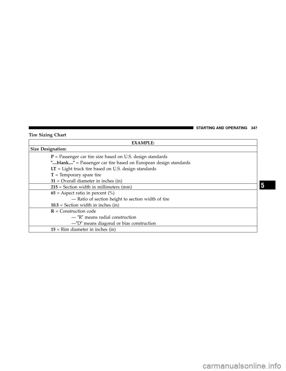
Tire Sizing Chart
EXAMPLE:
Size Designation:
P= Passenger car tire size based on U.S. design standards
�....blank....� = Passenger car tire based on European design standards
LT = Light truck tire based on U.S. design standards
T = Temporary spare tire
31 = Overall diameter in inches (in)
215 = Section width in millimeters (mm)
65 = Aspect ratio in percent (%)
— Ratio of section height to section width of tire
10.5 = Section width in inches (in)
R = Construction code
—�R� means radial construction
—�D� means diagonal or bias construction
15 = Rim diameter in inches (in)
5
STARTING AND OPERATING 347

•A clicking sound of solenoid valves
�")
, see
your authorized dealer as soon as possible to have the
problem diagnosed and corrected.
NOTE:
•The “ESP/TCS Indicator Light” and the “E")