2010 CHEVROLET HHR wheel torque
[x] Cancel search: wheel torquePage 208 of 480

Region A Gauge and Speedometer
Displays
Change the information displayed in Region A by
turning the knob either clockwise or counterclockwise.
The available gauges are:
BOOST:Displays positive boost pressure as
determined by the manifold air pressure (MAP) sensor.
AIR/FUEL RATIO: Displays the mass ratio of air to fuel.
CAM PHASER ANGLES: Displays orientation of the
intake and exhaust cam shafts relative to their park
positions as commanded by the engine control module.
OVERLAP represents the total distance the intake and
exhaust cam shafts have phased.
SPARK ADVANCE/ KNOCK RETARD: The spark
advance gauge displays ignition timing. Knock retard
indicates the amount of ignition delay to reduce spark
knock.
ENGINE POWER & TORQUE : Displayed engine
power and torque are engine flywheel output values
calculated by the engine control module. These
values are approximate and may change with the air
conditioning load, generator output, air temperature, air
pressure, and fuel octane. SPEEDOMETER & G FORCE :
The G FORCE meter
displays lateral acceleration. While turning right,
G forces are felt on the left, and vice versa. PEAK
values are stored indefinitely, and can be reset with
a press and hold of the RPD knob while viewing the
G FORCE meter.
SETUP MENU: Press the RPD knob to enter this
menu. The vehicle should be stopped while configuring
the setup menu selections.
SCREEN OFF: Turns the screen off.
Region B Readout Displays
Press the RPD knob to highlight Region B. The
information displayed can be changed by turning the
RPD knob either clockwise or counterclockwise.
Press the RPD knob again, to store the selection. The
selection will also be stored after a few seconds of no
activity. Available modes are:
Readouts #1
SHIFT LIGHTS/GEAR INDICATION: The shift lights
provide visual identification of engine speed for a
transmission gear. Shift light minimum and maximum
RPM settings can be viewed and configured in the
SETUP screen. The gear indication on manual
transmission vehicles is calculated by the engine
control module. The gear is only displayed when
enough torque is available to determine the selected
forward gear.
4-42
Page 341 of 480
Brake Wear
This vehicle has front disc brakes and could have rear
drum brakes or rear disc brakes.
Disc brake pads have built-in wear indicators that make
a high-pitched warning sound when the brake pads are
worn and new pads are needed. The sound can come
and go or be heard all the time the vehicle is moving,
except when applying the brake pedal firmly.
{WARNING:
The brake wear warning sound means that soon
the brakes will not work well. That could lead to
an accident. When the brake wear warning sound
is heard, have the vehicle serviced.
Notice: Continuing to drive with worn-out brake
pads could result in costly brake repair.
Some driving conditions or climates can cause a brake
squeal when the brakes are first applied or lightly
applied. This does not mean something is wrong with
the brakes. Properly torqued wheel nuts are necessary to help
prevent brake pulsation. When tires are rotated, inspect
brake pads for wear and evenly tighten wheel nuts in
the proper sequence to torque specifications in
Capacities and Specifications on page 6‑125.
If the vehicle has rear drum brakes, they do not
have wear indicators, but if a rear brake rubbing
noise is heard, have the rear brake linings inspected
immediately. Rear brake drums should be removed and
inspected each time the tires are removed for rotation or
changing. When the front brake pads are replaced,
have the rear brakes inspected, too.
Brake linings should always be replaced as complete
axle sets.
Brake Pedal Travel
See your dealer/retailer if the brake pedal does not
return to normal height, or if there is a rapid increase in
pedal travel. This could be a sign that brake service
might be required.
Brake Adjustment
Every time the brakes are applied, with or without the
vehicle moving, the brakes adjust for wear.
6-39
Page 372 of 480
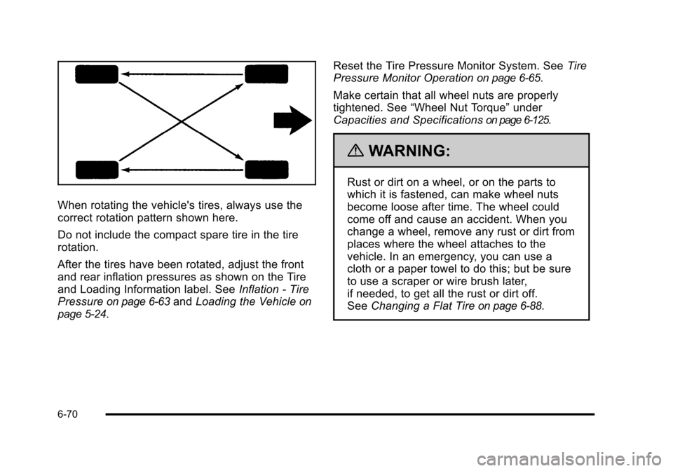
When rotating the vehicle's tires, always use the
correct rotation pattern shown here.
Do not include the compact spare tire in the tire
rotation.
After the tires have been rotated, adjust the front
and rear inflation pressures as shown on the Tire
and Loading Information label. SeeInflation - Tire
Pressure
on page 6‑63and Loading the Vehicleon
page 5‑24
. Reset the Tire Pressure Monitor System. See
Tire
Pressure Monitor Operation
on page 6‑65.
Make certain that all wheel nuts are properly
tightened. See “Wheel Nut Torque” under
Capacities and Specifications
on page 6‑125.
{WARNING:
Rust or dirt on a wheel, or on the parts to
which it is fastened, can make wheel nuts
become loose after time. The wheel could
come off and cause an accident. When you
change a wheel, remove any rust or dirt from
places where the wheel attaches to the
vehicle. In an emergency, you can use a
cloth or a paper towel to do this; but be sure
to use a scraper or wire brush later,
if needed, to get all the rust or dirt off.
See Changing a Flat Tire
on page 6‑88.
6-70
Page 398 of 480
{WARNING:
Wheel nuts that are improperly or incorrectly
tightened can cause the wheels to become loose
or come off. The wheel nuts should be tightened
with a torque wrench to the proper torque
specification after replacing. Follow the torque
specification supplied by the aftermarket
manufacturer when using accessory locking wheel
nuts. SeeCapacities and Specifications
on
page 6‑125
for original equipment wheel nut
torque specifications.
Notice: Improperly tightened wheel nuts can lead
to brake pulsation and rotor damage. To avoid
expensive brake repairs, evenly tighten the wheel
nuts in the proper sequence and to the proper
torque specification. See Capacities and
Specifications
on page 6‑125for the wheel nut
torque specification.
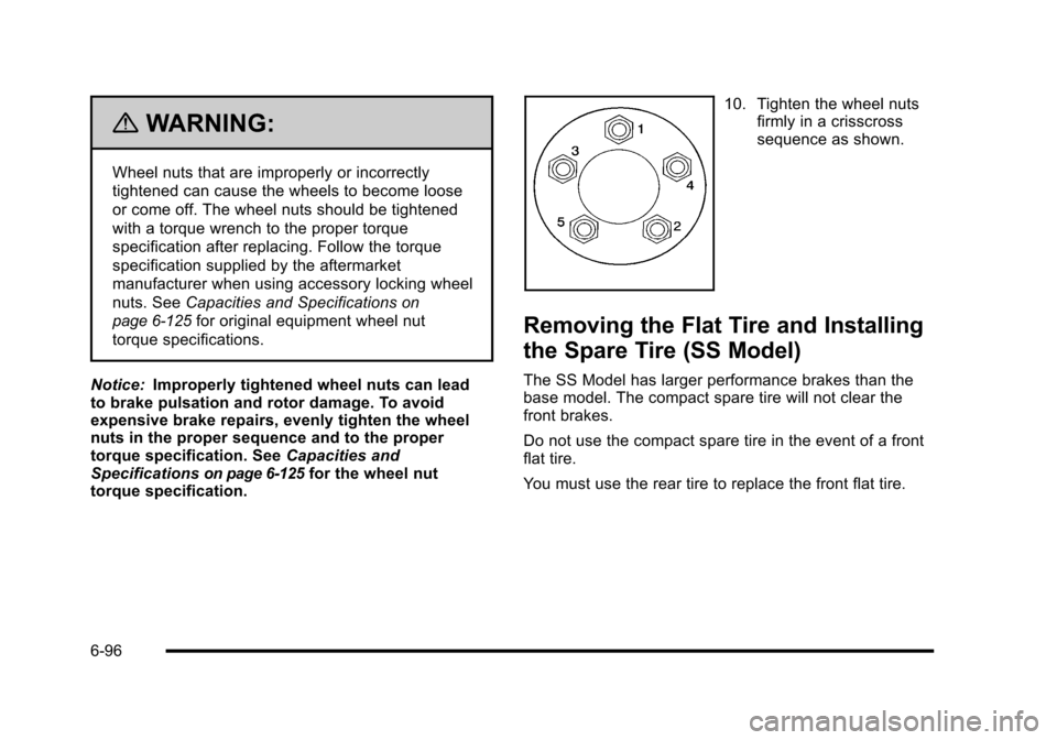
10. Tighten the wheel nuts
firmly in a crisscross
sequence as shown.
Removing the Flat Tire and Installing
the Spare Tire (SS Model)
The SS Model has larger performance brakes than the
base model. The compact spare tire will not clear the
front brakes.
Do not use the compact spare tire in the event of a front
flat tire.
You must use the rear tire to replace the front flat tire.
6-96
Page 402 of 480
{WARNING:
Never use oil or grease on bolts or nuts because
the nuts might come loose. The vehicle's wheel
could fall off, causing a crash.
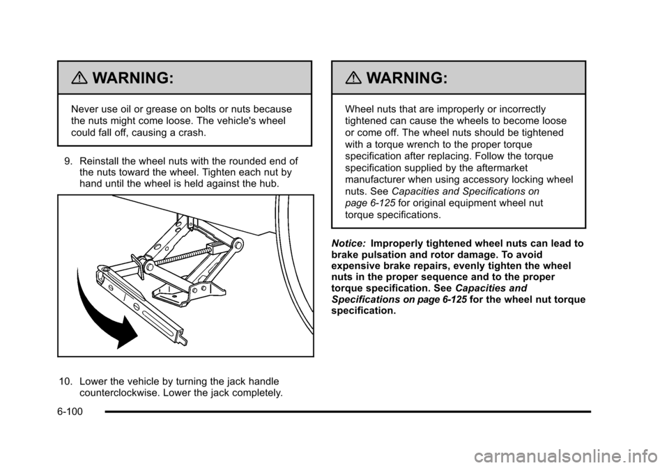
9. Reinstall the wheel nuts with the rounded end of the nuts toward the wheel. Tighten each nut by
hand until the wheel is held against the hub.
10. Lower the vehicle by turning the jack handle counterclockwise. Lower the jack completely.
{WARNING:
Wheel nuts that are improperly or incorrectly
tightened can cause the wheels to become loose
or come off. The wheel nuts should be tightened
with a torque wrench to the proper torque
specification after replacing. Follow the torque
specification supplied by the aftermarket
manufacturer when using accessory locking wheel
nuts. See Capacities and Specifications
on
page 6‑125
for original equipment wheel nut
torque specifications.
Notice: Improperly tightened wheel nuts can lead to
brake pulsation and rotor damage. To avoid
expensive brake repairs, evenly tighten the wheel
nuts in the proper sequence and to the proper
torque specification. See Capacities and
Specifications
on page 6‑125for the wheel nut torque
specification.
6-100
Page 407 of 480
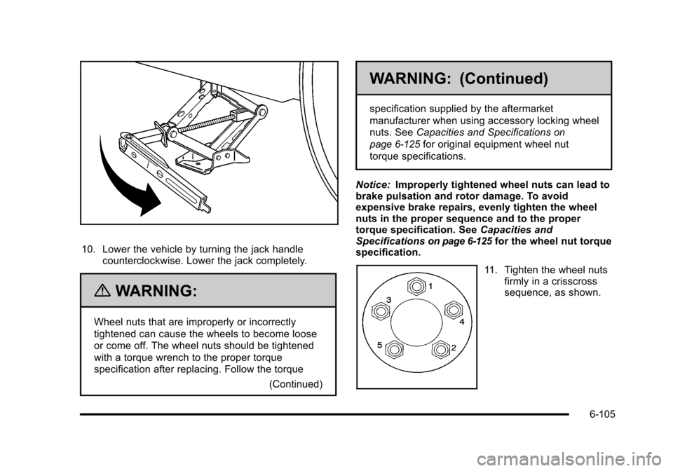
10. Lower the vehicle by turning the jack handlecounterclockwise. Lower the jack completely.
{WARNING:
Wheel nuts that are improperly or incorrectly
tightened can cause the wheels to become loose
or come off. The wheel nuts should be tightened
with a torque wrench to the proper torque
specification after replacing. Follow the torque
(Continued)
WARNING: (Continued)
specification supplied by the aftermarket
manufacturer when using accessory locking wheel
nuts. SeeCapacities and Specifications
on
page 6‑125
for original equipment wheel nut
torque specifications.
Notice: Improperly tightened wheel nuts can lead to
brake pulsation and rotor damage. To avoid
expensive brake repairs, evenly tighten the wheel
nuts in the proper sequence and to the proper
torque specification. See Capacities and
Specifications
on page 6‑125for the wheel nut torque
specification.
11. Tighten the wheel nuts firmly in a crisscross
sequence, as shown.
6-105
Page 427 of 480
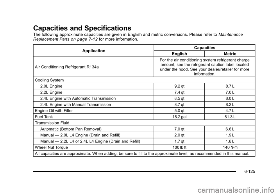
Capacities and Specifications
The following approximate capacities are given in English and metric conversions. Please refer toMaintenance
Replacement Partson page 7‑12for more information.
Application Capacities
English Metric
Air Conditioning Refrigerant R134a For the air conditioning system refrigerant charge
amount, see the refrigerant caution label located
under the hood. See your dealer/retailer for more
information.
Cooling System 2.0L Engine 9.2 qt8.7 L
2.2L Engine 7.4 qt7.0 L
2.4L Engine with Automatic Transmission 8.5 qt8.0 L
2.4L Engine with Manual Transmission 8.7 qt8.2 L
Engine Oil with Filter 5.0 qt4.7 L
Fuel Tank 16.2 gal61.3 L
Transmission Fluid Automatic (Bottom Pan Removal) 7.0 qt6.6 L
Manual —2.0L L4 Engine (Drain and Refill) 2.0 qt1.9 L
Manual —2.2L L4 or 2.4L L4 Engine (Drain and Refill) 1.7 qt1.6 L
Wheel Nut Torque 100 lb ft140Y
All capacities are approximate. When adding, be sure to fill to the approximate level, as recommended in this manual.
6-125