2010 CHEVROLET HHR engine
[x] Cancel search: enginePage 344 of 480
4. Open the hood on the other vehicle and locate thepositive (+) and negative (−) terminal locations on
that vehicle.
You will not see the battery of your vehicle under
the hood. It is located in the rear cargo area. You
will not need to access your battery for jump
starting. The vehicle has a remote positive (+) and
a remote negative (−) jump starting terminal.
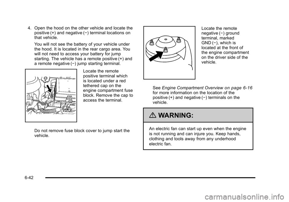
Locate the remote
positive terminal which
is located under a red
tethered cap on the
engine compartment fuse
block. Remove the cap to
access the terminal.
Do not remove fuse block cover to jump start the
vehicle.
Locate the remote
negative (−) ground
terminal, marked
GND (−), which is
located at the front of
the engine compartment
on the driver side of the
vehicle.
See Engine Compartment Overview
on page 6‑16for more information on the location of the
positive (+) and negative (−) terminals on the
vehicle.
{WARNING:
An electric fan can start up even when the engine
is not running and can injure you. Keep hands,
clothing and tools away from any underhood
electric fan.
6-42
Page 345 of 480
{WARNING:
Using a match near a battery can cause battery
gas to explode. People have been hurt doing this,
and some have been blinded. Use a flashlight if
you need more light.
Be sure the battery has enough water. You do not
need to add water to the battery installed in your
new vehicle. But if a battery has filler caps, be
sure the right amount of fluid is there. If it is low,
add water to take care of that first. If you don't,
explosive gas could be present.
Battery fluid contains acid that can burn you. Do
not get it on you. If you accidentally get it in your
eyes or on your skin, flush the place with water
and get medical help immediately.
{WARNING:
Fans or other moving engine parts can injure you
badly. Keep your hands away from moving parts
once the engine is running.
5. Check that the jumper cables do not have loose or missing insulation. If they do, you could get a
shock. The vehicles could be damaged too.
Before you connect the cables, here are some
basic things you should know. Positive (+) will go
to positive (+) or to a remote positive (+) terminal if
the vehicle has one. Negative (−) will go to a
heavy, unpainted metal engine part or to a remote
negative (−) terminal if the vehicle has one.
Do not connect positive (+) to negative (−) or you
will get a short that would damage the battery and
maybe other parts too. And do not connect the
negative (−) cable to the negative (−) terminal on
the dead battery because this can cause sparks.
6-43
Page 346 of 480
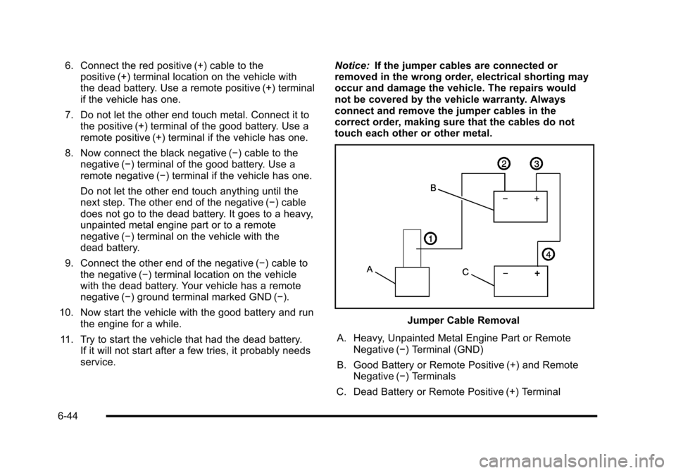
6. Connect the red positive (+) cable to thepositive (+) terminal location on the vehicle with
the dead battery. Use a remote positive (+) terminal
if the vehicle has one.
7. Do not let the other end touch metal. Connect it to the positive (+) terminal of the good battery. Use a
remote positive (+) terminal if the vehicle has one.
8. Now connect the black negative (−) cable to the negative (−) terminal of the good battery. Use a
remote negative (−) terminal if the vehicle has one.
Do not let the other end touch anything until the
next step. The other end of the negative (−) cable
does not go to the dead battery. It goes to a heavy,
unpainted metal engine part or to a remote
negative (−) terminal on the vehicle with the
dead battery.
9. Connect the other end of the negative (−) cable to the negative (−) terminal location on the vehicle
with the dead battery. Your vehicle has a remote
negative (−) ground terminal marked GND (−).
10. Now start the vehicle with the good battery and run the engine for a while.
11. Try to start the vehicle that had the dead battery. If it will not start after a few tries, it probably needs
service. Notice:
If the jumper cables are connected or
removed in the wrong order, electrical shorting may
occur and damage the vehicle. The repairs would
not be covered by the vehicle warranty. Always
connect and remove the jumper cables in the
correct order, making sure that the cables do not
touch each other or other metal.
Jumper Cable Removal
A. Heavy, Unpainted Metal Engine Part or Remote Negative (−) Terminal (GND)
B. Good Battery or Remote Positive (+) and Remote Negative (−) Terminals
C. Dead Battery or Remote Positive (+) Terminal
6-44
Page 361 of 480
Tire Size
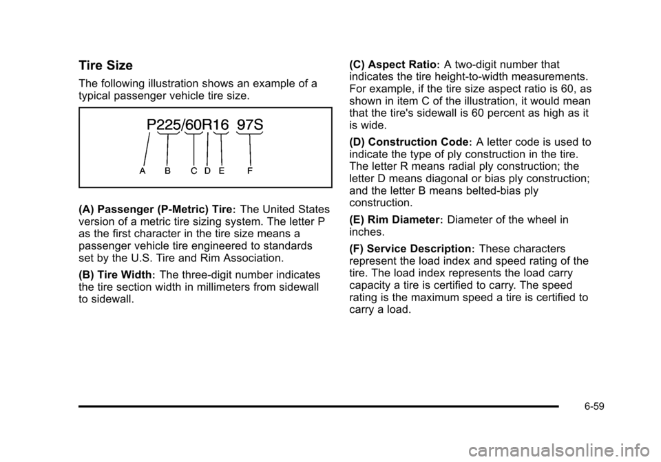
The following illustration shows an example of a
typical passenger vehicle tire size.
(A) Passenger (P‐Metric) Tire:The United States
version of a metric tire sizing system. The letter P
as the first character in the tire size means a
passenger vehicle tire engineered to standards
set by the U.S. Tire and Rim Association.
(B) Tire Width
:The three‐digit number indicates
the tire section width in millimeters from sidewall
to sidewall. (C) Aspect Ratio
:A two‐digit number that
indicates the tire height‐to‐width measurements.
For example, if the tire size aspect ratio is 60, as
shown in item C of the illustration, it would mean
that the tire's sidewall is 60 percent as high as it
is wide.
(D) Construction Code
:A letter code is used to
indicate the type of ply construction in the tire.
The letter R means radial ply construction; the
letter D means diagonal or bias ply construction;
and the letter B means belted‐bias ply
construction.
(E) Rim Diameter
:Diameter of the wheel in
inches.
(F) Service Description
:These characters
represent the load index and speed rating of the
tire. The load index represents the load carry
capacity a tire is certified to carry. The speed
rating is the maximum speed a tire is certified to
carry a load.
6-59
Page 370 of 480
TPMS Sensor Matching Process
Each TPMS sensor has a unique identification code.
Any time you replace one or more of the TPMS sensors
or rotate the vehicle's tires, the identification codes
need to be matched to the new tire/wheel location. The
sensors are matched, to the tire/wheel locations, in the
following order: driver side front tire, passenger side
front tire, passenger side rear tire, and driver side rear
tire using a TPMS diagnostic tool. See your dealer/
retailer for service.
The TPMS sensors can also be matched to each
tire/wheel position by increasing or decreasing the tire's
air pressure. When increasing the tire's pressure, do not
exceed the maximum inflation pressure indicated on the
tire's sidewall. To decrease the tire's air-pressure use
the pointed end of the valve cap, a pencil-style air
pressure gauge, or a key.
You have two minutes to match each tire and wheel
position. If it takes longer than two minutes to match
any tire and wheel position, the matching process stops
and you need to start over.
The TPMS matching process is outlined below:1. Set the parking brake.
2. Turn the ignition switch to ON/RUN with the engine off. 3. Press and hold the Remote Keyless Entry (RKE)
transmitter's LOCK and UNLOCK buttons, at the
same time, for about five seconds to start the
TPMS learn mode. The horn sounds twice
indicating the TPMS receiver is ready and in
learn mode.
4. Start with the driver side front tire. The driver side front turn signal also comes on to indicate that
corner's sensor is ready to be learned.
5. Remove the valve cap from the tire's valve stem. Activate the TPMS sensor by increasing or
decreasing the tire's air pressure for about
eight seconds. The horn chirp, can take up to
30 seconds to sound. It chirps one time and then
all the turn signals flash one time to confirm the
sensor identification code has been matched to the
tire/wheel position.
6. The passenger side front turn signal comes on to indicate that corner sensor is ready to be learned.
Proceed to the passenger side front tire and repeat
the procedure in Step 5.
7. The passenger side rear turn signal comes on to indicate that corner sensor is ready to be learned.
Proceed to the passenger side rear tire and repeat
the procedure in Step 5.
6-68
Page 380 of 480
A rear blowout, particularly on a curve, acts much like a
skid and may require the same correction you would
use in a skid. In any rear blowout remove your foot from
the accelerator pedal. Get the vehicle under control by
steering the way you want the vehicle to go. It may be
very bumpy and noisy, but you can still steer. Gently
brake to a stop, well off the road if possible.
{WARNING:
Lifting a vehicle and getting under it to do
maintenance or repairs is dangerous without the
appropriate safety equipment and training. If a
jack is provided with the vehicle, it is designed
only for changing a flat tire. If it is used for
anything else, you or others could be badly
injured or killed if the vehicle slips off the jack.
If a jack is provided with the vehicle, only use it
for changing a flat tire.
This vehicle may come with a jack and spare tire or a
tire sealant and compressor kit. To use the jack and
spare tire, follow the instructions below. To use the tire
sealant and compressor kit, see Tire Sealant and
Compressor Kit
on page 6‑78.
Tire Sealant and Compressor Kit
{WARNING:
Idling a vehicle in an enclosed area with poor
ventilation is dangerous. Engine exhaust may
enter the vehicle. Engine exhaust contains
Carbon Monoxide (CO) which cannot be seen or
smelled. It can cause unconsciousness and even
death. Never run the engine in an enclosed area
that has no fresh air ventilation. For more
information, see Engine Exhaust on page 3‑39.
{WARNING:
Over-inflating a tire could cause the tire to rupture
and you or others could be injured. Be sure to
read and follow the tire sealant and compressor
kit instructions and inflate the tire to its
recommended pressure. Do not exceed the
recommended pressure.
6-78
Page 390 of 480
Changing a Flat Tire
If a tire goes flat, avoid further tire and wheel damage
by driving slowly to a level place. Turn on the hazard
warning flashers. SeeHazard Warning Flashers
on
page 4‑3.
{WARNING:
Changing a tire can be dangerous. The vehicle
can slip off the jack and roll over or fall on you or
other people. You and they could be badly injured
or even killed. Find a level place to change your
tire. To help prevent the vehicle from moving:
1. Set the parking brake firmly.
2. Put an automatic transmission shift lever in P (Park), or shift a manual transmission to
1 (First) or R (Reverse).
(Continued)
WARNING: (Continued)
3. Turn off the engine and do not restart whilethe vehicle is raised.
4. Do not allow passengers to remain in the vehicle.
To be even more certain the vehicle will not move,
you should put blocks at the front and rear of the
tire farthest away from the one being changed.
That would be the tire on the other side, at the
opposite end of the vehicle.
When the vehicle has a flat tire (B), use the following
example as a guide to assist you in the placement of
wheel blocks (A).
6-88
Page 420 of 480
Vehicle Identification
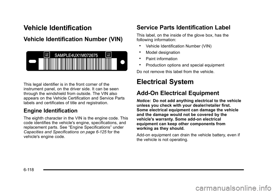
Vehicle Identification Number (VIN)
This legal identifier is in the front corner of the
instrument panel, on the driver side. It can be seen
through the windshield from outside. The VIN also
appears on the Vehicle Certification and Service Parts
labels and certificates of title and registration.
Engine Identification
The eighth character in the VIN is the engine code. This
code identifies the vehicle's engine, specifications, and
replacement parts. See“Engine Specifications”under
Capacities and Specifications
on page 6‑125for the
vehicle's engine code.
Service Parts Identification Label
This label, on the inside of the glove box, has the
following information:
.Vehicle Identification Number (VIN)
.Model designation
.Paint information
.Production options and special equipment
Do not remove this label from the vehicle.
Electrical System
Add-On Electrical Equipment
Notice: Do not add anything electrical to the vehicle
unless you check with your dealer/retailer first.
Some electrical equipment can damage the vehicle
and the damage would not be covered by the
vehicle's warranty. Some add-on electrical
equipment can keep other components from
working as they should.
Add-on equipment can drain the vehicle battery, even if
the vehicle is not operating.
6-118