Page 57 of 112

PERIODIC MAINTENANCE AND ADJUSTMENT
6-1
6
EAU17241
Periodic inspection, adjustment, and lu-
brication will keep your vehicle in the
safest and most efficient condition pos-
sible. Safety is an obligation of the vehi-
cle owner/operator. The most important
points of vehicle inspection, adjust-
ment, and lubrication are explained on
the following pages.
The intervals given in the periodic
maintenance and lubrication chart
should be simply considered as a gen-
eral guide under normal riding condi-
tions. However, depending on the
weather, terrain, geographical location,
and individual use, the maintenance in-
tervals may need to be shortened.
WARNING
EWA10321
Failure to properly maintain the ve-
hicle or performing maintenance ac-
tivities incorrectly may increase
your risk of injury or death during
service or while using the vehicle. If
you are not familiar with vehicle ser-
vice, have a Yamaha dealer performservice.
WARNING
EWA15121
Turn off the engine when performing
maintenance unless otherwise
specified.�
A running engine has moving
parts that can catch on body
parts or clothing and electrical
parts that can cause shocks or
fires.
�
Running the engine while ser-
vicing can lead to eye injury,
burns, fire, or carbon monoxide
poisoning – possibly leading to
death. See page 1-1 for more in-
formation about carbon monox-ide.
EAU17361
Owner’s tool kit The owner’s tool kit is located under the
rider seat. (See page 3-25.)
The service information included in this
manual and the tools provided in the
owner’s tool kit are intended to assist
you in the performance of preventive
maintenance and minor repairs. How-
ever, additional tools such as a torque
wrench may be necessary to perform
certain maintenance work correctly.TIPIf you do not have the tools or experi-
ence required for a particular job, havea Yamaha dealer perform it for you.1. Owner’s tool kit
1
U14BE0E0.book Page 1 Friday, November 21, 2008 9:23 AM
Page 58 of 112

PERIODIC MAINTENANCE AND ADJUSTMENT
6-2
6
EAU46860
TIP�
The annual checks must be performed every year, except if a kilometer-based maintenance, or for the UK, a
mileage-based maintenance, is performed instead.
�
From 50000 km (30000 mi), repeat the maintenance intervals starting from 10000 km (6000 mi).
�
Items marked with an asterisk should be performed by a Yamaha dealer as they require special tools, data and technicalskills.
EAU46910
Periodic maintenance chart for the emission control system NO. ITEM CHECK OR MAINTENANCE JOBODOMETER READING
ANNUAL
CHECK 1000 km
(600 mi)10000 km
(6000 mi)20000 km
(12000 mi)30000 km
(18000 mi)40000 km
(24000 mi)
1*Fuel lineCheck fuel hoses for cracks or
damage.√√√√√
2*Spark plugsCheck condition.
Clean and regap.√√
Replace.√√
3*ValvesCheck valve clearance.
Adjust.Every 40000 km (24000 mi)
4*Fuel injection sys-
temAdjust synchronization.√√√√√
5*Muffler and exhaust
pipeCheck the screw clamp(s) for
looseness.√√√√√
6*Air induction sys-
temCheck the air cut-off valve, reed
valve, and hose for damage.
Replace any damaged parts if
necessary.√√√√√
U14BE0E0.book Page 2 Friday, November 21, 2008 9:23 AM
Page 59 of 112
10000 km
(6000 mi)20000 k")
PERIODIC MAINTENANCE AND ADJUSTMENT
6-3
6
EAU1770B
General maintenance and lubrication chart NO. ITEM CHECK OR MAINTENANCE JOBODOMETER READING
ANNUAL
CHECK 1000 km
(600 mi)10000 km
(6000 mi)20000 km
(12000 mi)30000 km
(18000 mi)40000 km
(24000 mi)
1 Air filter elementReplace.√
2ClutchCheck operation.
Adjust.√√√√√
3*Front brakeCheck operation, fluid level and
vehicle for fluid leakage.√√√√√√
Replace brake pads. Whenever worn to the limit
4*Rear brakeCheck operation, fluid level and
vehicle for fluid leakage.√√√√√√
Replace brake pads. Whenever worn to the limit
5*Brake hosesCheck for cracks or damage.√√√√√
Replace. Every 4 years
6*WheelsCheck runout and for damage.√√√√
7*TiresCheck tread depth and for dam-
age.
Replace if necessary.
Check air pressure.
Correct if necessary.√√√√√
8*Wheel bearingsCheck bearing for looseness or
damage.√√√√
9*SwingarmCheck operation and for exces-
sive play.√√√√
Lubricate with lithium-soap-based
grease.Every 50000 km (30000 mi)
U14BE0E0.book Page 3 Friday, November 21, 2008 9:23 AM
Page 60 of 112

PERIODIC MAINTENANCE AND ADJUSTMENT
6-4
6
10 Drive chainCheck chain slack, alignment and
condition.
Adjust and lubricate chain with a
special O-ring chain lubricant
thoroughly. Every 800 km (500 mi) and after washing the motorcycle or riding in the rain
11*Steering bearingsCheck bearing play and steering
for roughness.√√√√√
Lubricate with lithium-soap-based
grease.Every 20000 km (12000 mi)
12*Steering damperCheck operation and for oil leak-
age.√√√√
13*Chassis fastenersMake sure that all nuts, bolts and
screws are properly tightened.√√√√√
14Brake lever pivot
shaftLubricate with silicone grease.√√√√√
15Brake pedal pivot
shaftLubricate with lithium-soap-based
grease.√√√√√
16Clutch lever pivot
shaftLubricate with lithium-soap-based
grease.√√√√√
17Shift pedal pivot
shaftLubricate with lithium-soap-based
grease.√√√√√
18 SidestandCheck operation.
Lubricate.√√√√√
19*Sidestand switchCheck operation.√√√√√√
20*Front forkCheck operation and for oil leak-
age.√√√√ NO. ITEM CHECK OR MAINTENANCE JOBODOMETER READING
ANNUAL
CHECK 1000 km
(600 mi)10000 km
(6000 mi)20000 km
(12000 mi)30000 km
(18000 mi)40000 km
(24000 mi)U14BE0E0.book Page 4 Friday, November 21, 2008 9:23 AM
Page 61 of 112

PERIODIC MAINTENANCE AND ADJUSTMENT
6-5
6
21*Shock absorber as-
semblyCheck operation and shock ab-
sorber for oil leakage.√√√√
22*Rear suspension re-
lay arm and con-
necting arm
pivoting pointsCheck operation.√√√√
23 Engine oilChange.
Check oil level and vehicle for oil
leakage.√√√√√√
24Engine oil filter car-
tridgeReplace.√√√
25*Cooling systemCheck coolant level and vehicle
for coolant leakage.√√√√√
Change. Every 3 years
26*Front and rear brake
switchesCheck operation.√√√√√√
27Moving parts and
cablesLubricate.√√√√√
28*Throttle grip hous-
ing and cableCheck operation and free play.
Adjust the throttle cable free play
if necessary.
Lubricate the throttle grip housing
and cable.√√√√√
29*Lights, signals and
switchesCheck operation.
Adjust headlight beam.√√√√√√ NO. ITEM CHECK OR MAINTENANCE JOBODOMETER READING
ANNUAL
CHECK 1000 km
(600 mi)10000 km
(6000 mi)20000 km
(12000 mi)30000 km
(18000 mi)40000 km
(24000 mi)
U14BE0E0.book Page 5 Friday, November 21, 2008 9:23 AM
Page 62 of 112
PERIODIC MAINTENANCE AND ADJUSTMENT
6-6
6
EAU18680
TIP�
Air filter
This model’s air filter is equipped with a disposable oil-coated paper element, which must not be cleaned with com-
pressed air to avoid damaging it.
The air filter element needs to be replaced more frequently when riding in unusually wet or dusty areas.
�
Hydraulic brake service
Regularly check and, if necessary, correct the brake fluid level.
Every two years replace the internal components of the brake master cylinders and calipers, and change the brake
fluid.Replace the brake hoses every four years and if cracked or damaged.
U14BE0E0.book Page 6 Friday, November 21, 2008 9:23 AM
Page 63 of 112
PERIODIC MAINTENANCE AND ADJUSTMENT
6-7
6
EAU18712
Removing and installing cowl-
ings and panels The cowlings and panels shown need
to be removed to perform some of the
maintenance jobs described in this
chapter. Refer to this section each time
a cowling or panel needs to be re-
moved and installed.
EAU47251
Cowlings A and B
To remove one of the cowlings1. Remove the quick fastener screws
and the quick fasteners, and then
take the cowling off.
2. Disconnect the turn signal light
lead coupler.
1. Panel A
2. Cowling A
3. Cowling C1
2
3
1. Panel B
2. Cowling B
3. Cowling D
1
2
3
1. Quick fastener screw
1. Cowling A
2. Cowling B
3. Quick fastener1
1
1
3
2
3
U14BE0E0.book Page 7 Friday, November 21, 2008 9:23 AM
Page 64 of 112
PERIODIC MAINTENANCE AND ADJUSTMENT
6-8
6To install the cowling
1. Connect the turn signal light lead
coupler.
2. Fit the projections on the cowling
into the slots as shown.3. Install the quick fasteners and the
quick fastener screws.
EAU47242
Cowlings C and D
To remove one of the cowlings1. Remove cowling A (if removing
cowling C) or cowling B (if remov-
ing cowling D). (See page 6-7.)
2. Remove the quick fastener
screws.3. Slide the cowling forward to un-
hook its projection from the slot,
and then pull the cowling off.
1. Turn signal light lead coupler
1. Slot
2. Projection
1
2
1
1. Slot
2. Projection
1
2
1. Cowling C
2. Quick fastener screw
1. Slot
2. Projection
22
2 2
1
1
2
U14BE0E0.book Page 8 Friday, November 21, 2008 9:23 AM
 1
1 2
2 3
3 4
4 5
5 6
6 7
7 8
8 9
9 10
10 11
11 12
12 13
13 14
14 15
15 16
16 17
17 18
18 19
19 20
20 21
21 22
22 23
23 24
24 25
25 26
26 27
27 28
28 29
29 30
30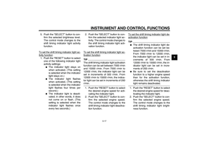 31
31 32
32 33
33 34
34 35
35 36
36 37
37 38
38 39
39 40
40 41
41 42
42 43
43 44
44 45
45 46
46 47
47 48
48 49
49 50
50 51
51 52
52 53
53 54
54 55
55 56
56 57
57 58
58 59
59 60
60 61
61 62
62 63
63 64
64 65
65 66
66 67
67 68
68 69
69 70
70 71
71 72
72 73
73 74
74 75
75 76
76 77
77 78
78 79
79 80
80 81
81 82
82 83
83 84
84 85
85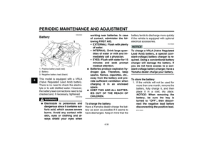 86
86 87
87 88
88 89
89 90
90 91
91 92
92 93
93 94
94 95
95 96
96 97
97 98
98 99
99 100
100 101
101 102
102 103
103 104
104 105
105 106
106 107
107 108
108 109
109 110
110 111
111

