Page 17 of 112

INSTRUMENT AND CONTROL FUNCTIONS
3-3
3
EAU10471
Main switch/steering lock The main switch/steering lock controls
the ignition and lighting systems, and is
used to lock the steering.TIPBe sure to use the standard key (black
bow) for regular use of the vehicle. To
minimize the risk of losing the code re-
registering key (red bow), keep it in a
safe place and only use it for code re-registering.
EAU10550
ON
All electrical circuits are supplied with
power, the meter lighting, taillight, li-
cense plate light and auxiliary lights
come on, and the engine can be start-
ed. The key cannot be removed.TIPThe headlights come on automatically
when the engine is started and stay on
until the key is turned to “OFF”, even ifthe engine stalls.
EAU10661
OFF
All electrical systems are off. The key
can be removed.
WARNING
EWA10061
Never turn the key to “OFF” or
“LOCK” while the vehicle is moving.
Otherwise the electrical systems will
be switched off, which may result inloss of control or an accident.
EAU10681
LOCK
The steering is locked, and all electrical
systems are off. The key can be re-
moved.
To lock the steering1. Turn the handlebars all the way to
the left.
2. Push the key in from the “OFF” po-
sition, and then turn it to “LOCK”
while still pushing it.
3. Remove the key.1. Push.
2. Turn.
U14BE0E0.book Page 3 Friday, November 21, 2008 9:23 AM
Page 18 of 112

The steering is locked, and the taillight,
licen")
INSTRUMENT AND CONTROL FUNCTIONS
3-4
3To unlock the steering
Push the key in, and then turn it to
“OFF” while still pushing it.
EAU10941
(Parking)
The steering is locked, and the taillight,
license plate light and auxiliary lights
are on. The hazard lights and turn sig-
nal lights can be turned on, but all other
electrical systems are off. The key can
be removed.
The steering must be locked before the
key can be turned to“”.
NOTICE
ECA11020
Do not use the parking position for
an extended length of time, other-wise the battery may discharge.
EAU11004
Indicator and warning lights
EAU11030
Turn signal indicator lights“”
and“”
The corresponding indicator light flash-
es when the turn signal switch is
pushed to the left or right.
1. Push.
2. Turn.
1. Shift timing indicator light
2. Engine trouble warning light“”
3. Oil level warning light“”
4. Coolant temperature warning light“”
5. Steering damper warning light“”
6. Right turn signal indicator light“”
7. High beam indicator light“”
8. Neutral indicator light“”
9. Fuel level warning light“”
10.Left turn signal indicator light“”
11.Immobilizer system indicator light12
34561178910
U14BE0E0.book Page 4 Friday, November 21, 2008 9:23 AM
Page 19 of 112

INSTRUMENT AND CONTROL FUNCTIONS
3-5
3
EAU11060
Neutral indicator light“”
This indicator light comes on when the
transmission is in the neutral position.
EAU11080
High beam indicator light“”
This indicator light comes on when the
high beam of the headlight is switched
on.
EAU11254
Oil level warning light“”
This warning light comes on if the en-
gine oil level is low.
The electrical circuit of the warning light
can be checked by turning the key to
“ON”. The warning light should come
on for a few seconds, and then go off.
If the warning light does not come on
initially when the key is turned to “ON”,
or if the warning light remains on, have
a Yamaha dealer check the electrical
circuit.TIP�
Even if the oil level is sufficient, the
warning light may flicker when
riding on a slope or during sudden
acceleration or deceleration, but
this is not a malfunction.
�
This model is also equipped with a
self-diagnosis device for the oil
level detection circuit. If a problem
is detected in the oil level detection
circuit, the following cycle will be
repeated until the malfunction is
corrected: The oil level warning
light will flash ten times, then go off
for 2.5 seconds. If this occurs,
have a Yamaha dealer check thevehicle.
EAU11365
Fuel level warning light“”
This warning light comes on when the
fuel level drops below approximately
3.1 L (0.82 US gal, 0.68 Imp.gal). When
this occurs, refuel as soon as possible.
The electrical circuit of the warning light
can be checked by turning the key to
“ON”. The warning light should come
on for a few seconds, and then go off.
If the warning light does not come on
initially when the key is turned to “ON”,
or if the warning light remains on, have
a Yamaha dealer check the electrical
circuit.
TIPThis model is also equipped with a self-
diagnosis device for the fuel level de-
tection circuit. If a problem is detected
in the fuel level detection circuit, the fol-
lowing cycle will be repeated until the
malfunction is corrected: The fuel level
warning light will flash eight times, and
then go off for 3.0 seconds. If this oc-
curs, have a Yamaha dealer check thevehicle.
EAU47750
Coolant temperature warning
light“”
This warning light comes on if the en-
gine overheats. If this occurs, stop the
engine immediately and allow the en-
gine to cool.
The electrical circuit of the warning light
can be checked by turning the key to
“ON”. The warning light should come
on for a few seconds, and then go off.
If the warning light does not come on
initially when the key is turned to “ON”,
or if the warning light remains on, have
a Yamaha dealer check the electrical
circuit.
U14BE0E0.book Page 5 Friday, November 21, 2008 9:23 AM
Page 20 of 112
INSTRUMENT AND CONTROL FUNCTIONS
3-6
3
NOTICE
ECA10021
Do not continue to operate the en-gine if it is overheating.TIP�
For radiator-fan-equipped vehi-
cles, the radiator fan(s) automati-
cally switch on or off according to
the coolant temperature in the ra-
diator.
�
If the engine overheats, see page6-41 for further instructions.
U14BE0E0.book Page 6 Friday, November 21, 2008 9:23 AM
Page 21 of 112
INSTRUMENT AND CONTROL FUNCTIONS
3-7
3
Coolant
temperatureDisplay Conditions What to do
Under 39 °C
(Under 103 °F)Message “Lo” is displayed. OK. Go ahead with riding.
40–116 °C
(104–242 °F)Temperature is displayed. OK. Go ahead with riding.
Above 117 °C
(Above 243 °F)Temperature display flashes.
Warning light comes on.Stop the vehicle and allow it to idle until
the coolant temperature goes down.
If the temperature does not go down,
stop the engine. (See page 6-41.)
U14BE0E0.book Page 7 Friday, November 21, 2008 9:23 AM
Page 22 of 112

INSTRUMENT AND CONTROL FUNCTIONS
3-8
3
EAU11534
Engine trouble warning light“”
This warning light comes on or flashes
if a problem is detected in the electrical
circuit monitoring the engine. If this oc-
curs, have a Yamaha dealer check the
self-diagnosis system. (See page 3-15
for an explanation of the self-diagnosis
device.)
The electrical circuit of the warning light
can be checked by turning the key to
“ON”. The warning light should come
on for a few seconds, and then go off.
If the warning light does not come on
initially when the key is turned to “ON”,
or if the warning light remains on, have
a Yamaha dealer check the electrical
circuit.
EAU47481
Steering damper warning light“”
This warning light comes on and an er-
ror code is displayed if a problem is de-
tected in the steering damper. If this
occurs, have a Yamaha dealer check
the self-diagnosis system. (See page
3-15 for an explanation of the self-diag-
nosis device.)The electrical circuit of the warning light
can be checked by turning the key to
“ON”. The warning light should come
on for a few seconds, and then go off.
If the warning light does not come on
initially when the key is turned to “ON”,
or if the warning light remains on, have
a Yamaha dealer check the electrical
circuit.
EAU11574
Shift timing indicator light
This indicator light can be set to come
on and go off at the desired engine
speeds and is used to inform the rider
when it is time to shift to the next higher
gear.
The electrical circuit of the indicator
light can be checked by turning the key
to “ON”. The indicator light should
come on for a few seconds, and then
go off.
If the indicator light does not come on
initially when the key is turned to “ON”,
or if the indicator light remains on, have
a Yamaha dealer check the electrical
circuit. (See page 3-16 for a detailed
explanation of the function of this indi-
cator light and on how to set it.)
EAU38623
Immobilizer system indicator light
The electrical circuit of the indicator
light can be checked by turning the key
to “ON”. The indicator light should
come on for a few seconds, and then
go off.
If the indicator light does not come on
initially when the key is turned to “ON”,
or if the indicator light remains on, have
a Yamaha dealer check the electrical
circuit.
When the key is turned to “OFF” and 30
seconds have passed, the indicator
light will start flashing indicating the im-
mobilizer system is enabled. After 24
hours have passed, the indicator light
will stop flashing, however the immobi-
lizer system is still enabled.
This model is also equipped with a self-
diagnosis device for the immobilizer
system. (See page 3-15 for an explana-
tion of the self-diagnosis device.)
U14BE0E0.book Page 8 Friday, November 21, 2008 9:23 AM
Page 23 of 112

INSTRUMENT AND CONTROL FUNCTIONS
3-9
3
EAU47612
Multi-function meter unit
WARNING
EWA12422
Be sure to stop the vehicle before
making any setting changes to the
multi-function meter unit. Changingsettings while riding can distract the
operator and increase the risk of an
accident.
The multi-function meter unit is
equipped with the following:�
a speedometer
�
a tachometer
�
an odometer
�
two tripmeters (which show the
distance traveled since they were
last set to zero)
�
a fuel reserve tripmeter (which
shows the distance traveled since
the fuel level warning light came
on)
�
a stopwatch
�
a clock
�
a coolant temperature display
�
an air intake temperature display
�
a transmission gear display
�
a drive mode display (which shows
the selected drive mode)
�
a throttle opening position display
�
a fuel consumption display (instan-
taneous and average consumption
functions)
�
a self-diagnosis device
�
a display brightness, shift timing
indicator light and throttle opening
position display control mode
TIP�
Be sure to turn the key to “ON” be-
fore using the “SELECT” and “RE-
SET” buttons.
�
For the U.K. only: To switch the
speedometer and odometer/trip-
meter/fuel consumption displays
between kilometers and miles,
press the “SELECT” button for atleast one second.
Tachometer
1.“RESET” button
2.“SELECT” button
3. Tachometer
4. Shift timing indicator light
5. Throttle opening position display
6. Coolant temperature display/air intake tem-
perature display
7. Mode display
8. Speedometer
9. Odometer/tripmeter/fuel reserve tripmeter/in-
stantaneous fuel consumption/average fuel
consumption
10.Clock/stopwatch
11.Transmission gear display2
134
5
6
7
8
9
10 11
1. Tachometer
2. Tachometer red zone
2 1
U14BE0E0.book Page 9 Friday, November 21, 2008 9:23 AM
Page 24 of 112

INSTRUMENT AND CONTROL FUNCTIONS
3-10
3The electric tachometer allows the rider
to monitor the engine speed and keep it
within the ideal power range.
When the key is turned to “ON”, the ta-
chometer needle sweeps once across
the r/min range and then returns to zero
r/min in order to test the electrical cir-
cuit.
NOTICE
ECA10031
Do not operate the engine in the ta-
chometer red zone.Red zone: 13750 r/min and above
Clock and stopwatch modesTo set the clock
1. Push the “SELECT” button and
“RESET” button together for at
least two seconds.
2. When the hour digits start flashing,
push the “RESET” button to set the
hours.
3. Push the “SELECT” button, and
the minute digits start flashing.
4. Push the “RESET” button to set
the minutes.
5. Push the “SELECT” button and
then release it to start the clock.
To display the stopwatchTo change the display to the stopwatch
mode, push the “SELECT” button and
“RESET” button together. To change
the display back to the clock mode,
push the “SELECT” button and “RE-
SET” button together; however, this is
not possible when the stopwatch is
counting.
Standard measurement1. Push the “RESET” button to start
the stopwatch.
2. Push the “SELECT” button to stop
the stopwatch.3. Push the “SELECT” button again
to reset the stopwatch.
Split time measurement
1. Push the “RESET” button to start
the stopwatch.
2. Push the “RESET” button or start
switch“” to measure split times.
Split times are displayed on the
odometer display for five seconds.
3. Push the “RESET” button or start
switch“” to display the final split
time or push the “SELECT” button
to stop the stopwatch and display
the total elapsed time.
Split time history
1. Clock/stopwatch
1
1. Coolant temperature display/air intake tem-
perature display
2. Stopwatch
21
U14BE0E0.book Page 10 Friday, November 21, 2008 9:23 AM
 1
1 2
2 3
3 4
4 5
5 6
6 7
7 8
8 9
9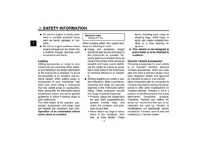 10
10 11
11 12
12 13
13 14
14 15
15 16
16 17
17 18
18 19
19 20
20 21
21 22
22 23
23 24
24 25
25 26
26 27
27 28
28 29
29 30
30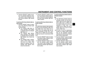 31
31 32
32 33
33 34
34 35
35 36
36 37
37 38
38 39
39 40
40 41
41 42
42 43
43 44
44 45
45 46
46 47
47 48
48 49
49 50
50 51
51 52
52 53
53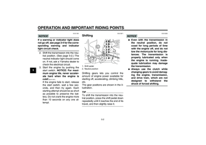 54
54 55
55 56
56 57
57 58
58 59
59 60
60 61
61 62
62 63
63 64
64 65
65 66
66 67
67 68
68 69
69 70
70 71
71 72
72 73
73 74
74 75
75 76
76 77
77 78
78 79
79 80
80 81
81 82
82 83
83 84
84 85
85 86
86 87
87 88
88 89
89 90
90 91
91 92
92 93
93 94
94 95
95 96
96 97
97 98
98 99
99 100
100 101
101 102
102 103
103 104
104 105
105 106
106 107
107 108
108 109
109 110
110 111
111
Message “Lo” is displayed. OK. Go ahead with riding.
40–116 °C
(104–242")