Page 25 of 112

INSTRUMENT AND CONTROL FUNCTIONS
3-11
3 The split time history displays up to 20
stored split times. The split time history
can be displayed either in reverse chro-
nological order or by speed.
1. Push the “SELECT” button for at
least one second to select the re-
verse chronological order mode;
“L-20” displays on the stopwatch.
Push the “SELECT” button again
to select the speed mode; “F-20”
displays on the stopwatch.
2. Push the “RESET” button. De-
pending on the selected split time,
“L20” or “F20” displays on the cool-
ant temperature display/air intake
temperature display, and its corre-
sponding stored split time displays
on the stopwatch.
3. Push the “SELECT” button to
move down, and the “RESET” but-
ton to move up through the list.
TIP�
When displaying in the reverse
chronological order, the split times
are shown from the latest to earli-
est (i.e., L20, L19, L18, L17).
When displaying in the speed or-der, the split times are shown from
the fastest to slowest (i.e., F01,
F02, F03, F04).
�
Push the “RESET” button for at
least one second to reset all the re-
corded times for the selected splittime history.
4. Push the “SELECT” button for at
least one second to cancel the split
time history and return to the time
measurement.
Odometer, tripmeter, instantaneous
fuel consumption and average fuel
consumption modesPush the “SELECT” button to switch
the display between the odometer
mode “ODO”, the tripmeter modes
“TRIP 1” and “TRIP 2”, the instanta-
neous fuel consumption mode “km/L”
or “L/100 km”, and the average fuel
consumption mode “AV_ _._ km/L” or
“AV_ _._ L/100 km” in the following or-
der:
ODO → TRIP 1 → TRIP 2 → km/L or
L/100 km → AV_ _._ km/L or AV_ _._
L/100 km → ODO
For the UK only:
Push the “SELECT” button to switch
the display between the odometer
mode “ODO”, the tripmeter modes
“TRIP 1” and “TRIP 2”, the instanta-
neous fuel consumption mode “km/L”,
“L/100 km” or “MPG”, and the average
fuel consumption mode “AV_ _._
km/L”, “AV_ _._ L/100 km” or “AV_ _._
MPG” in the following order:
ODO → TRIP 1 → TRIP 2 → km/L,
L/100 km or MPG → AV_ _._ km/L,
AV_ _._ L/100 km or AV_ _._ MPG →
ODO
1. Odometer/tripmeter/fuel reserve tripmeter/in-
stantaneous fuel consumption/average fuel
consumption
1
U14BE0E0.book Page 11 Friday, November 21, 2008 9:23 AM
Page 26 of 112
, the display automatical-
ly changes to the fuel reserve tripmeter
mode “TRIP F” and starts counting")
INSTRUMENT AND CONTROL FUNCTIONS
3-12
3If the fuel level warning light comes on
(see page 3-4), the display automatical-
ly changes to the fuel reserve tripmeter
mode “TRIP F” and starts counting the
distance traveled from that point. In that
case, push the “SELECT” button to
switch the display between the various
tripmeter, odometer, instantaneous fuel
consumption and average fuel con-
sumption modes in the following order:
TRIP F → km/L or L/100 km → AV_ _._
km/L or AV_ _._ L/100 km → ODO →
TRIP 1 → TRIP 2 → TRIP F
For the UK only:
TRIP F → km/L, L/100 km or MPG →
AV_ _._ km/L, AV_ _._ L/100 km or
AV_ _._ MPG → ODO → TRIP 1 →
TRIP 2 → TRIP F
To reset a tripmeter, select it by push-
ing the “SELECT” button, and then
push the “RESET” button for at least
one second.If you do not reset the fuel reserve trip-
meter manually, it resets itself automat-
ically and the display returns to the prior
mode after refueling and traveling 5 km
(3 mi).
Instantaneous fuel consumption mode
The instantaneous fuel consumption
display can be set to either “km/L”,
“L/100 km” or “MPG” (for the UK only).�
When the display is set to “km/L”,
the distance that can be traveled
on 1.0 L of fuel under the current
riding conditions is shown.
�
When the display is set to “L/100
km”, the amount of fuel necessary
to travel 100 km under the current
riding conditions is shown.
�
For the UK only: When the display
is set to “MPG”, the distance that
can be traveled on 1.0 Imp.gal of
fuel under the current riding condi-
tions is shown.
To switch between the instantaneous
fuel consumption displays, push the
“SELECT” button for one second when
one of the displays is shown.
TIPIf traveling at speeds under 10 km/h(6.0 mi/h), “_ _._” is displayed.
Average fuel consumption mode
1. Instantaneous fuel consumption
1
1. Average fuel consumption
1
U14BE0E0.book Page 12 Friday, November 21, 2008 9:23 AM
Page 27 of 112
.
This display shows")
INSTRUMENT AND CONTROL FUNCTIONS
3-13
3 The average fuel consumption display
can be set to either “AV_ _._ km/L”,
“AV_ _._ L/100 km” or “AV_ _._ MPG”
(for the UK only).
This display shows the average fuel
consumption since it was last reset.
�
When the display is set to “AV_ _._
km/L”, the average distance that
can be traveled on 1.0 L of fuel is
shown.
�
When the display is set to “AV_ _._
L/100km”, the average amount of
fuel necessary to travel 100 km is
shown.
�
For the UK only: When the display
is set to “AV_ _._ MPG”, the aver-
age distance that can be traveled
on 1.0 Imp.gal of fuel is shown.
To switch between the average fuel
consumption displays, push the “SE-
LECT” button for one second when one
of the displays is shown.
To reset the average fuel consumption
display, select it by pushing the “SE-
LECT” button, and then push the “RE-
SET” button for at least one second.
TIPAfter resetting an average fuel con-
sumption display, “_ _._” is shown for
that display until the vehicle has trav-eled 1 km (0.6 mi).
Transmission gear display
This display shows the selected gear.
The neutral position is indicated by“”
and by the neutral indicator light.Throttle opening position display
The throttle opening position display
shows how much the throttle is being
opened. The number of segments in-
creases as the throttle is being opened.
Refer to “Display brightness and shift
timing indicator light control mode” on
page 3-16.
TIPThe segments are displayed when theengine is running.
1. Neutral indicator light“”
2. Transmission gear display
21
1. Throttle opening position display
1
U14BE0E0.book Page 13 Friday, November 21, 2008 9:23 AM
Page 28 of 112

INSTRUMENT AND CONTROL FUNCTIONS
3-14
3Mode display
This display indicates which drive
mode has been selected: “STD”, “A” or
“B”. For more details on the modes and
on how to select them, refer to pages
3-1 and 3-19.Coolant temperature display
The coolant temperature display indi-
cates the temperature of the coolant.
TIPWhen the coolant temperature display
is selected, “C” is displayed for one
second, and then the coolant tempera-ture is displayed.NOTICE
ECA10021
Do not continue to operate the en-gine if it is overheating.Air intake temperature display
The air intake temperature display indi-
cates the temperature of the air drawn
into the air filter case. Turn the key to
“ON”, and push the “RESET” button to
switch the coolant temperature display
to the air intake temperature display.
Push the “RESET” button again to re-
turn to the coolant temperature display.
TIP�
Even if the air intake temperature
is set to be displayed, the coolant
temperature warning light comes
on if the engine overheats.
1. Mode display
1
1. Coolant temperature display
1
1. Air intake temperature display
1
U14BE0E0.book Page 14 Friday, November 21, 2008 9:23 AM
Page 29 of 112

INSTRUMENT AND CONTROL FUNCTIONS
3-15
3
�
When the key is turned to “ON”,
the coolant temperature is auto-
matically displayed, even if the air
intake temperature was displayed
prior to turning the key to “OFF”.
�
When the air intake temperature
display is selected, “A” is displayedbefore the temperature.
Self-diagnosis device
This model is equipped with a self-diag-
nosis device for various electrical cir-
cuits.
If a problem is detected in any of those
circuits, the engine trouble warning light
comes on and the display indicates an
error code.The self-diagnosis device also detects
problems in the immobilizer system cir-
cuits.
If a problem is detected in the immobi-
lizer system circuits, the immobilizer
system indicator light flashes and the
display indicates an error code.
TIPIf the display indicates error code 52,
this could be caused by transponder in-
terference. If this error code appears,try the following.
1. Use the code re-registering key to
start the engine.TIPMake sure there are no other immobi-
lizer keys close to the main switch, and
do not keep more than one immobilizer
key on the same key ring! Immobilizer
system keys may cause signal interfer-
ence, which may prevent the enginefrom starting.
2. If the engine starts, turn it off and
try starting the engine with the
standard keys.3. If one or both of the standard keys
do not start the engine, take the
vehicle, the code re-registering
key and both standard keys to a
Yamaha dealer and have the stan-
dard keys re-registered.
If the display indicates any error codes,
note the code number, and then have a
Yamaha dealer check the vehicle.
NOTICE
ECA11590
If the display indicates an error
code, the vehicle should be checked
as soon as possible in order to avoidengine damage.
1. Error code display
1
U14BE0E0.book Page 15 Friday, November 21, 2008 9:23 AM
Page 30 of 112

INSTRUMENT AND CONTROL FUNCTIONS
3-16
3Display brightness, shift timing indi-
cator light and throttle opening posi-
tion display control mode
This mode allows you to make changes
to six settings by performing the follow-
ing steps.
1. Turn the key to “OFF”.
2. Push and hold the “SELECT” but-
ton.
3. Turn the key to “ON”, and then re-
lease the “SELECT” button after
five seconds. The display bright-
ness function is selected.4. Push the “SELECT” button to
switch the functions in the order
below.
a. Display brightness:
This function allows you to ad-
just the brightness of the dis-
plays and tachometer to suit
the outside lighting conditions.
b. Shift timing indicator light activ-
ity:
This function allows you to
choose whether or not the indi-
cator light should be activated
and whether it should flash or
stay on when activated.
c. Shift timing indicator light acti-
vation:
This function allows you to se-
lect the engine speed at which
the indicator light is activated.
d. Shift timing indicator light deac-
tivation:
This function allows you to se-
lect the engine speed at which
the indicator light is deactivat-
ed.
e. Shift timing indicator light
brightness:This function allows you to ad-
just the brightness of the indi-
cator light to suit your
preference.
f. Throttle opening position dis-
play:
This function allows you to
choose whether or not to show
the throttle opening position
display.
TIPThe display shows the current setting
for each function, except the shift timingindicator light activity function.
To adjust the brightness of the multi-function meter displays and tachometer1. Turn the key to “OFF”.
2. Push and hold the “SELECT” but-
ton.
3. Turn the key to “ON”, and then re-
lease the “SELECT” button after
five seconds.
4. Push the “RESET” button to select
the desired brightness level.
1. Shift timing indicator light activation range
2. Shift timing indicator light
3. Brightness adjustable displays
4. Brightness level
1
2
3
4
U14BE0E0.book Page 16 Friday, November 21, 2008 9:23 AM
Page 31 of 112

INSTRUMENT AND CONTROL FUNCTIONS
3-17
3 5. Push the “SELECT” button to con-
firm the selected brightness level.
The control mode changes to the
shift timing indicator light activity
function.
To set the shift timing indicator light ac-
tivity function1. Push the “RESET” button to select
one of the following indicator light
activity settings:
�
The indicator light stays on
when activated. (This setting
is selected when the indicator
light stays on.)
�
The indicator light flashes
when activated. (This setting
is selected when the indicator
light flashes four times per
second.)
�
The indicator light is deacti-
vated; in other words, it does
not come on or flash. (This
setting is selected when the
indicator light flashes once
every two seconds.)2. Push the “SELECT” button to con-
firm the selected indicator light ac-
tivity. The control mode changes to
the shift timing indicator light acti-
vation function.
To set the shift timing indicator light ac-
tivation functionTIPThe shift timing indicator light activation
function can be set between 7000 r/min
and 15000 r/min. From 7000 r/min to
12000 r/min, the indicator light can be
set in increments of 500 r/min. From
12000 r/min to 15000 r/min, the indica-
tor light can be set in increments of 200r/min.
1. Push the “RESET” button to select
the desired engine speed for acti-
vating the indicator light.
2. Push the “SELECT” button to con-
firm the selected engine speed.
The control mode changes to the
shift timing indicator light deactiva-
tion function.To set the shift timing indicator light de-
activation functionTIP�
The shift timing indicator light de-
activation function can be set be-
tween 7000 r/min and 15000 r/min.
From 7000 r/min to 12000 r/min,
the indicator light can be set in in-
crements of 500 r/min. From
12000 r/min to 15000 r/min, the in-
dicator light can be set in incre-
ments of 200 r/min.
�
Be sure to set the deactivation
function to a higher engine speed
than for the activation function,
otherwise the shift timing indicatorlight remains deactivated.
1. Push the “RESET” button to select
the desired engine speed for deac-
tivating the indicator light.
2. Push the “SELECT” button to con-
firm the selected engine speed.
The control mode changes to the
shift timing indicator light bright-
ness function.
U14BE0E0.book Page 17 Friday, November 21, 2008 9:23 AM
Page 32 of 112

INSTRUMENT AND CONTROL FUNCTIONS
3-18
3To adjust the shift timing indicator light
brightness1. Push the “RESET” button to select
the desired indicator light bright-
ness level.
2. Push the “SELECT” button to con-
firm the selected indicator light
brightness level. The control mode
changes to the throttle opening po-
sition display.
To set the throttle opening position dis-play1. Push the “RESET” button to select
one of the following activity set-
tings:
�
The throttle opening seg-
ments and “R1” are displayed.
�
“R1” is displayed only.
�
Neither throttle opening seg-
ments nor “R1” are displayed.
2. Push the “SELECT” button to con-
firm the selected throttle opening
position display activity. The dis-
play returns to the odometer or
tripmeter mode.
EAU12331
Anti-theft alarm (optional) This model can be equipped with an
optional anti-theft alarm by a Yamaha
dealer. Contact a Yamaha dealer for
more information.
EAU12348
Handlebar switches Left1. Pass switch “PASS”
2. Dimmer switch“/”
3. Turn signal switch“/”
4. Horn switch“”
5. Hazard switch“”
U14BE0E0.book Page 18 Friday, November 21, 2008 9:23 AM
 1
1 2
2 3
3 4
4 5
5 6
6 7
7 8
8 9
9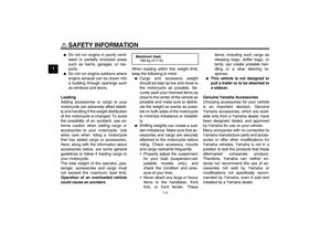 10
10 11
11 12
12 13
13 14
14 15
15 16
16 17
17 18
18 19
19 20
20 21
21 22
22 23
23 24
24 25
25 26
26 27
27 28
28 29
29 30
30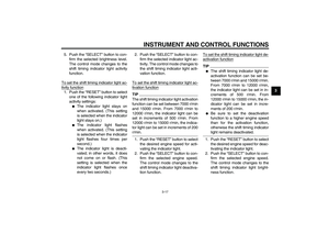 31
31 32
32 33
33 34
34 35
35 36
36 37
37 38
38 39
39 40
40 41
41 42
42 43
43 44
44 45
45 46
46 47
47 48
48 49
49 50
50 51
51 52
52 53
53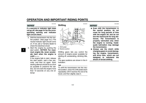 54
54 55
55 56
56 57
57 58
58 59
59 60
60 61
61 62
62 63
63 64
64 65
65 66
66 67
67 68
68 69
69 70
70 71
71 72
72 73
73 74
74 75
75 76
76 77
77 78
78 79
79 80
80 81
81 82
82 83
83 84
84 85
85 86
86 87
87 88
88 89
89 90
90 91
91 92
92 93
93 94
94 95
95 96
96 97
97 98
98 99
99 100
100 101
101 102
102 103
103 104
104 105
105 106
106 107
107 108
108 109
109 110
110 111
111