Page 57 of 94

PERIODIC MAINTENANCE AND ADJUSTMENT
6-12
6 3. Pull the air filter element out.
4. Insert a new air filter element into
the air filter case. NOTICE: Make
sure that the air filter element is
properly seated in the air filter
case. The engine should never
be operated without the air filter
element installed, otherwise the
piston(s) and/or cylinder(s) may
become excessively worn.
[ECA10481]
5. Install the air filter case cover by in-
stalling the screws.
6. Install the panel.To clean the air filter check hose
1. Check the hose on the front of the
air filter case for accumulated dirt
or water.
2. If dirt or water is visible, remove
the hose, clean it, and then install
it.
EAU21382
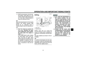
Checking the throttle cable
free play The throttle cable free play should mea-
sure 3.0–5.0 mm (0.12–0.20 in) at the
throttle grip. Periodically check the
throttle cable free play and, if neces-
sary, have a Yamaha dealer adjust it.
1. Air filter element
1. Air filter check hose
1. Throttle cable free play
U5WME6E0.book Page 12 Wednesday, August 20, 2008 3:23 PM
Page 58 of 94

PERIODIC MAINTENANCE AND ADJUSTMENT
6-13
6
EAU21401
Valve clearance The valve clearance changes with use,
resulting in improper air-fuel mixture
and/or engine noise. To prevent this
from occurring, the valve clearance
must be adjusted by a Yamaha dealer
at the intervals specified in the periodic
maintenance and lubrication chart.
EAU21772
Tires To maximize the performance, durabil-
ity, and safe operation of your motor-
cycle, note the following points
regarding the specified tires.
Tire air pressure
The tire air pressure should be checked
and, if necessary, adjusted before each
ride.
WARNING
EWA10501
Operation of this vehicle with im-
proper tire pressure may cause se-
vere injury or death from loss of
control.�
The tire air pressure must be
checked and adjusted on cold
tires (i.e., when the temperature
of the tires equals the ambient
temperature).
�
The tire air pressure must be ad-
justed in accordance with the
riding speed and with the total
weight of rider, passenger, car-
go, and accessories approvedfor this model.
WARNING
EWA10511
Never overload your vehicle. Opera-
tion of an overloaded vehicle couldcause an accident.Tire air pressure (measured on cold
tires):
0–90 kg (0–198 lb):
Front:
250 kPa (2.50 kgf/cm², 36 psi)
Rear:
250 kPa (2.50 kgf/cm², 36 psi)
90–205 kg (198–452 lb):
Front:
250 kPa (2.50 kgf/cm², 36 psi)
Rear:
290 kPa (2.90 kgf/cm², 42 psi)
High-speed riding:
Front:
250 kPa (2.50 kgf/cm², 36 psi)
Rear:
290 kPa (2.90 kgf/cm², 42 psi)
Maximum load*:
205 kg (452 lb)
* Total weight of rider, passenger, car-
go and accessories
U5WME6E0.book Page 13 Wednesday, August 20, 2008 3:23 PM
Page 59 of 94

PERIODIC MAINTENANCE AND ADJUSTMENT
6-14
6 Tire inspection
The tires must be checked before each
ride. If the center tread depth reaches
the specified limit, if the tire has a nail or
glass fragments in it, or if the sidewall is
cracked, have a Yamaha dealer re-
place the tire immediately.
TIPThe tire tread depth limits may differ
from country to country. Always complywith the local regulations.
WARNING
EWA10470
�
Have a Yamaha dealer replace
excessively worn tires. Besides
being illegal, operating the vehi-
cle with excessively worn tires
decreases riding stability and
can lead to loss of control.
�
The replacement of all wheel
and brake related parts, includ-
ing the tires, should be left to a
Yamaha dealer, who has the
necessary professional knowl-edge and experience.
Tire informationThis motorcycle is equipped with cast
wheels and tubeless tires with valves.
WARNING
EWA10481
�
The front and rear tires should
be of the same make and de-
sign, otherwise the handling
characteristics of the motor-
cycle may be different, which
could lead to an accident.
�
Always make sure that the valve
caps are securely installed to
prevent air pressure leakage.
�
Use only the tire valves and
valve cores listed below to
avoid tire deflation during ahigh-speed ride.
After extensive tests, only the tires list-
ed below have been approved for this
model by Yamaha Motor Co., Ltd.
1. Tire sidewall
2. Tire tread depthMinimum tire tread depth (front and
rear):
1.6 mm (0.06 in)
1. Tire air valve
2. Tire air valve core
3. Tire air valve cap with seal
U5WME6E0.book Page 14 Wednesday, August 20, 2008 3:23 PM
Page 60 of 94

PERIODIC MAINTENANCE AND ADJUSTMENT
6-15
6
WARNING
EWA10600
This motorcycle is fitted with super-
high-speed tires. Note the following
points in order to make the most ef-
ficient use of these tires.�
Use only the specified replace-
ment tires. Other tires may run
the danger of bursting at super
high speeds.
�
Brand-new tires can have a rela-
tively poor grip on certain road
surfaces until they have been
“broken in”. Therefore, it is ad-
visable before doing any high-speed riding to ride conserva-
tively for approximately 100 km
(60 mi) after installing a new tire.
�
The tires must be warmed up
before a high-speed run.
�
Always adjust the tire air pres-
sure according to the operatingconditions.
EAU21960
Cast wheels To maximize the performance, durabil-
ity, and safe operation of your vehicle,
note the following points regarding the
specified wheels.�
The wheel rims should be checked
for cracks, bends or warpage be-
fore each ride. If any damage is
found, have a Yamaha dealer re-
place the wheel. Do not attempt
even the smallest repair to the
wheel. A deformed or cracked
wheel must be replaced.
�
The wheel should be balanced
whenever either the tire or wheel
has been changed or replaced. An
unbalanced wheel can result in
poor performance, adverse han-
dling characteristics, and a short-
ened tire life.
�
Ride at moderate speeds after
changing a tire since the tire sur-
face must first be “broken in” for it
to develop its optimal characteris-
tics.
Front tire:
Size:
120/70 ZR17M/C (58W)
Manufacturer/model:
DUNLOP/D252F L
Rear tire:
Size:
180/55 ZR17M/C (73W)
Manufacturer/model:
DUNLOP/D252 L
FRONT and REAR:
Tire air valve:
TR412
Va l ve c o r e :
#9100 (original)
U5WME6E0.book Page 15 Wednesday, August 20, 2008 3:23 PM
Page 61 of 94

PERIODIC MAINTENANCE AND ADJUSTMENT
6-16
6
EAU22073
Clutch lever Since this model is equipped with a hy-
draulic clutch, adjusting the clutch lever
free play is not needed. However, it is
necessary to check the clutch fluid level
and check the hydraulic system for
leakage before each ride. (See page
6-17.) If the clutch lever free play does
become excessive, and shifting be-
comes rough or clutch slippage occurs,
causing poor acceleration, there may
be air in the clutch system. If there is air
in the hydraulic system, have a
Yamaha dealer bleed the system be-
fore operating the motorcycle.
EAU22292
Adjusting the rear brake light
switch The rear brake light, which is activated
by the brake pedal, should come on just
before braking takes effect. If neces-
sary, adjust the brake light switch as
follows.
1. Remove panel A. (See page 6-6.)
2. Turn the adjusting nut while hold-
ing the rear brake light switch in
place. To make the brake light
come on earlier, turn the adjusting
nut in direction (a). To make the
brake light come on later, turn the
adjusting nut in direction (b).
3. Install the panel.
EAU22321
Checking the front and rear
brake pads Front brake
Rear brake
1. Rear brake light switch
2. Rear brake light switch adjusting nut
1. Brake pad wear indicator groove
1. Brake pad wear indicator groove
U5WME6E0.book Page 16 Wednesday, August 20, 2008 3:23 PM
Page 62 of 94

PERIODIC MAINTENANCE AND ADJUSTMENT
6-17
6The front and rear brake pads must be
checked for wear at the intervals spec-
ified in the periodic maintenance and
lubrication chart. Each brake pad is
provided with a wear indicator groove,
which allows you to check the brake
pad wear without having to disassem-
ble the brake. To check the brake pad
wear, check the wear indicator
grooves. If a brake pad has worn to the
point that the wear indicator groove has
almost disappeared, have a Yamaha
dealer replace the brake pads as a set.
EAU22680
Checking the brake and clutch
fluid levels Front brake
Rear brakeClutch
Insufficient brake fluid may allow air to
enter the brake or clutch systems, pos-
sibly causing them to become ineffec-
tive.
Before riding, check that the brake fluid
is above the minimum level mark and
replenish if necessary. A low brake fluid
level may indicate worn brake pads
and/or brake system leakage. If the
brake level is low, be sure to check the
brake pads for wear and the brake sys-
tem for leakage.
TIPThe rear brake fluid reservoir is locatedbehind panel A. (See page 6-6.)
Observe these precautions:
1. Minimum level mark
1. Minimum level mark
1
1. Minimum level mark
1
U5WME6E0.book Page 17 Wednesday, August 20, 2008 3:23 PM
Page 63 of 94

PERIODIC MAINTENANCE AND ADJUSTMENT
6-18
6
�
When checking the fluid level,
make sure that the top of the brake
or clutch fluid reservoir is level.
�
Use only the recommended quality
brake fluid, otherwise the rubber
seals may deteriorate, causing
leakage and poor braking or clutch
performance.
�
Refill with the same type of brake
fluid. Mixing fluids may result in a
harmful chemical reaction and
lead to poor braking or clutch per-
formance.
�
The brake or clutch fluid reservoir
diaphragm will lose its shape from
the negative pressure if the fluid
level goes down too far. Be sure to
return the diaphragm to its original
shape before installing it into the
brake or clutch fluid reservoir.
�
Be careful that water does not en-
ter the brake or clutch fluid reser-
voir when refilling. Water willsignificantly lower the boiling point
of the fluid and may result in vapor
lock.
�
Brake fluid may deteriorate paint-
ed surfaces or plastic parts. Al-
ways clean up spilled fluid
immediately.
�
As the brake pads wear, it is nor-
mal for the brake fluid level to grad-
ually go down. However, if the
brake fluid level goes down sud-
denly, have a Yamaha dealer
check the cause.
EAU22751
Changing the brake and
clutch fluids Have a Yamaha dealer change the
brake and clutch fluids at the intervals
specified in the TIP after the periodic
maintenance and lubrication chart. In
addition, have the oil seals of the brake
and clutch master cylinders and cali-
pers as well as the brake and clutch
hoses replaced at the intervals listed
below or whenever they are damaged
or leaking.�
Oil seals: Replace every two
years.
�
Brake and clutch hoses: Replace
every four years.
Recommended brake and clutch flu-
id:
DOT 4 brake fluid
U5WME6E0.book Page 18 Wednesday, August 20, 2008 3:23 PM
Page 64 of 94

PERIODIC MAINTENANCE AND ADJUSTMENT
6-19
6
EAU22760
Drive chain slack The drive chain slack should be
checked before each ride and adjusted
if necessary.
EAU22793
To check the drive chain slack
1. Place the motorcycle on the cen-
terstand.
2. Shift the transmission into the neu-
tral position.
3. Spin the rear wheel several times
to locate the tightest portion of the
drive chain.
4. Measure the drive chain slack as
shown.5. If the drive chain slack is incorrect,
adjust it as follows.
EAU34313
To adjust the drive chain slack
1. Loosen the axle nut and the lock-
nut on each side of the swingarm.
2. To tighten the drive chain, turn the
drive chain slack adjusting bolt on
each side of the swingarm in direc-
tion (a). To loosen the drive chain,
turn the adjusting bolt on each side
of the swingarm in direction (b),
and then push the rear wheel for-
ward. NOTICE: Improper drive
chain slack will overload the en-
gine as well as other vital parts
of the motorcycle and can lead
to chain slippage or breakage.
To prevent this from occurring,
keep the drive chain slack with-
in the specified limits.
[ECA10571]
TIPUsing the alignment marks on each
side of the swingarm, make sure that
both chain pullers are in the same posi-tion for proper wheel alignment.
3. Tighten the locknuts, then the axle
nut to their specified torques.
1. Drive chain slack
Drive chain slack:
20.0–30.0 mm (0.79–1.18 in)
1. Locknut
2. Drive chain slack adjusting bolt
3. Axle nut
4. Alignment marks
5. Chain pullerTightening torques:
Locknut:
16 Nm (1.6 m·kgf, 11 ft·lbf)
Axle nut:
150 Nm (15.0 m·kgf, 110 ft·lbf)
U5WME6E0.book Page 19 Wednesday, August 20, 2008 3:23 PM