Page 57 of 96

PERIODIC MAINTENANCE AND ADJUSTMENT
6-16
2
3
4
5
67
8
9
then install the cap.
18. Start the engine, and then check
the vehicle for coolant leakage. If
coolant is leaking, have a Yamaha
dealer check the cooling system.
19. Install the panels.
EAU44322
Cleaning the air filter element
and check hose
The air filter element should be cleaned
at the intervals specified in the periodic
maintenance and lubrication chart.
Clean the air filter element more fre-
quently if you are riding in unusually
wet or dusty areas. In addition, the air
filter check hose must be frequently
checked and cleaned if necessary.
To clean the air filter element
1. Remove panel B. (See page 6-7.)
2. Open the air filter case cover by re-
moving the screw and pulling the
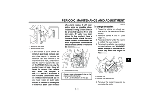
case cover outward as shown.3. Unhook the holding clip, and then
pull the air filter element out.
4. Remove the sponge material from
the air filter element frame, clean it
with solvent, and then squeeze the
remaining solvent out.
1. Screw
2. Air filter case cover
2
1
1. Holding clip
2. Air filter element
1
2
Page 58 of 96

PERIODIC MAINTENANCE AND ADJUSTMENT
6-17
1
2
3
4
5
6
7
8
9
5. Apply oil of the recommended type
to the entire surface of the sponge
material, and then squeeze the ex-
cess oil out.
TIP
The sponge material should be wet but
not dripping.
6. Pull the sponge material over the
air filter element frame.
7. Insert the air filter element into the
air filter case.
NOTICE:
Make sure
that the air filter element is prop-
erly seated in the air filter case.
The engine should never be op-
erated without the air filter ele-
ment installed, otherwise the
piston(s) and/or cylinder(s) may
become excessively worn.
[ECA10481]
8. Place the holding clip in the origi-
nal position.
9. Close the air filter case cover, and
then install the screw.
10. Install the panel.
To clean the air filter check hose
1. Check the hose at the bottom of
the air filter case for accumulated
dirt or water.2. If dirt or water is visible, remove
the hose, clean it, and then install
it.
1. Sponge material
2. Air filter element frame
1
2
12
3
4
Recommended oil:
Yamaha foam air filter oil or other
quality foam air filter oil
1. Air filter check hose
1
Page 59 of 96

PERIODIC MAINTENANCE AND ADJUSTMENT
6-18
2
3
4
5
67
8
9
EAU45322
Adjusting the engine idling
speed
The engine idling speed must be
checked and, if necessary, adjusted as
follows.
TIP
A digital tachometer is needed to make
this adjustment.
1. Position the digital tachometer at
the ignition coil, which is located in
the spark plug cap.
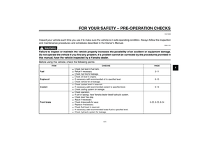
2. Check the engine idling speed
and, if necessary, adjust it to spec-
ification by turning the idle adjust-
ing screw. To increase the engine
idling speed, turn the screw in di-
rection (a). To decrease the en-
gine idling speed, turn the screw in
direction (b).
TIP
If the specified idling speed cannot be
obtained as described above, have a
Yamaha dealer make the adjustment.
EAU21382
Checking the throttle cable
free play
The throttle cable free play should mea-
sure 3.0–5.0 mm (0.12–0.20 in) at the
throttle grip. Periodically check the
throttle cable free play and, if neces-
sary, have a Yamaha dealer adjust it.
1. Idle adjusting screw
Engine idling speed:
1450–1650 r/min
1
(b)
(a)
1. Throttle cable free play
1
Page 60 of 96

PERIODIC MAINTENANCE AND ADJUSTMENT
6-19
1
2
3
4
5
6
7
8
9
EAU21401
Valve clearance
The valve clearance changes with use,
resulting in improper air-fuel mixture
and/or engine noise. To prevent this
from occurring, the valve clearance
must be adjusted by a Yamaha dealer
at the intervals specified in the periodic
maintenance and lubrication chart.
EAU21641
Tires
To maximize the performance, durabil-
ity, and safe operation of your motorcy-
cle, note the following points regarding
the specified tires.
Tire air pressure
The tire air pressure should be checked
and, if necessary, adjusted before each
ride.
WARNING
EWA10501
Operation of this vehicle with im-
proper tire pressure may cause se-
vere injury or death from loss of
control.
�
The tire air pressure must be
checked and adjusted on cold
tires (i.e., when the temperature
of the tires equals the ambient
temperature).
�
The tire air pressure must be ad-
justed in accordance with the
riding speed and with the total
weight of rider, passenger, car-
go, and accessories approved
for this model.
WARNING
EWA10511
Never overload your vehicle. Opera-
tion of an overloaded vehicle could
cause an accident.
Tire air pressure (measured on cold
tires):
0–90 kg (0–198 lb):
Front:
125 kPa (1.25 kgf/cm
2
, 18 psi)
Rear:
175 kPa (1.75 kgf/cm
2
, 25 psi)
90–185 kg (198–408 lb):
Front:
150 kPa (1.50 kgf/cm
2
, 22 psi)
Rear:
200 kPa (2.00 kgf/cm
2
, 29 psi)
Maximum load*:
185 kg (408 lb)
* Total weight of rider, passenger, car-
go and accessories
Page 61 of 96

PERIODIC MAINTENANCE AND ADJUSTMENT
6-20
2
3
4
5
67
8
9 Tire inspection
The tires must be checked before each
ride. If the center tread depth reaches
the specified limit, if the tire has a nail or
glass fragments in it, or if the sidewall is
cracked, have a Yamaha dealer re-
place the tire immediately.
TIP
The tire tread depth limits may differ
from country to country. Always comply
with the local regulations.
Tire information
This motorcycle is equipped with tube
tires.
WARNING
EWA10461
The front and rear tires should be of
the same make and design, other-
wise the handling characteristics of
the vehicle may be different, which
could lead to an accident.
After extensive tests, only the tires list-
ed below have been approved for this
model by Yamaha Motor Co., Ltd.
WARNING
EWA10570
�
Have a Yamaha dealer replace
excessively worn tires. Besides
being illegal, operating the mo-torcycle with excessively worn
tires decreases riding stability
and can lead to loss of control.
�
The replacement of all wheel-
and brake-related parts, includ-
ing the tires, should be left to a
Yamaha dealer, who has the
necessary professional knowl-
edge and experience.
�
It is not recommended to patch
a punctured tube. If unavoid-
able, however, patch the tube
very carefully and replace it as
soon as possible with a
high-quality product.
1. Tire sidewall
2. Tire tread depth
Minimum tire tread depth (front and
rear):
1.6 mm (0.06 in)
12
Front tire:
Size:
80/100-21M/C 51P
Manufacturer/model:
BRIDGESTONE/TW-301 F
Rear tire:
Size:
120/80-18M/C 62P
Manufacturer/model:
BRIDGESTONE/TW-302 F
Page 62 of 96

PERIODIC MAINTENANCE AND ADJUSTMENT
6-21
1
2
3
4
5
6
7
8
9
EAU21940
Spoke wheels
To maximize the performance, durabil-
ity, and safe operation of your motorcy-
cle, note the following points regarding
the specified wheels.
�
The wheel rims should be checked
for cracks, bends or warpage, and
the spokes for looseness or dam-
age before each ride. If any dam-
age is found, have a Yamaha
dealer replace the wheel. Do not
attempt even the smallest repair to
the wheel. A deformed or cracked
wheel must be replaced.
�
The wheel should be balanced
whenever either the tire or wheel
has been changed or replaced. An
unbalanced wheel can result in
poor performance, adverse han-
dling characteristics, and a short-
ened tire life.
�
Ride at moderate speeds after
changing a tire since the tire sur-
face must first be “broken in” for it
to develop its optimal characteris-
tics.
EAU22034
Adjusting the clutch lever free
play
The clutch lever free play should mea-
sure 10.0–15.0 mm (0.39–0.59 in) as
shown. Periodically check the clutch le-
ver free play and, if necessary, adjust it
as follows.
1. Slide the rubber cover back at the
clutch lever.
2. Loosen the locknut.
3. To increase the clutch lever free
play, turn the clutch lever free play
adjusting bolt in direction (a). Todecrease the clutch lever free play,
turn the adjusting bolt in direction
(b).
TIP
If the specified clutch lever free play
could be obtained as described above,
skip steps 4–7.
4. Fully turn the adjusting bolt in di-
rection (a) to loosen the clutch ca-
ble.
5. Loosen the locknut further down
the clutch cable.
6. To increase the clutch lever free
play, turn the clutch lever free play
1. Clutch lever free play
2. Locknut (clutch lever)
3. Adjusting bolt (clutch lever)
4. Rubber cover
3 2
1
(a)(b)
4
1. Locknut (clutch cable)
2. Clutch lever free play adjusting nut
(clutch cable)
12
(a)
(b)
Page 63 of 96
. To
decrease the clutch lever free play,
turn the adjusting nut in direction
(b).
7. Tighten the locknut at")
PERIODIC MAINTENANCE AND ADJUSTMENT
6-22
2
3
4
5
67
8
9
adjusting nut in direction (a). To
decrease the clutch lever free play,
turn the adjusting nut in direction
(b).
7. Tighten the locknut at the clutch
cable.
8. Tighten the locknut at the clutch le-
ver, and then slide the rubber cov-
er to its original position.
EAU22093
Adjusting the brake lever free
play
The brake lever free play should mea-
sure 5.0–8.0 mm (0.20–0.31 in) as
shown. Periodically check the brake le-
ver free play and, if necessary, adjust it
as follows.
1. Loosen the locknut at the brake le-
ver.
2. To increase the brake lever free
play, turn the brake lever free play
adjusting screw in direction (a). To
decrease the brake lever free play,
turn the adjusting screw in direc-tion (b).
3. Tighten the locknut.
WARNING
EWA10630
�
After adjusting the brake lever
free play, check the free play
and make sure that the brake is
working properly.
�
A soft or spongy feeling in the
brake lever can indicate the
presence of air in the hydraulic
system. If there is air in the hy-
draulic system, have a Yamaha
dealer bleed the system before
operating the motorcycle. Air in
the hydraulic system will dimin-
ish the braking performance,
which may result in loss of con-
trol and an accident.
1. Locknut
2. Brake lever free play adjusting screw
3. Brake lever free play
3
1
2
(b)
(a)
Page 64 of 96

PERIODIC MAINTENANCE AND ADJUSTMENT
6-23
1
2
3
4
5
6
7
8
9
EAU22272
Adjusting the rear brake light
switch
The rear brake light, which is activated
by the brake pedal, should come on just
before braking takes effect. If neces-
sary, adjust the rear brake light switch
as follows.
Turn the rear brake light switch adjust-
ing nut while holding the rear brake light
switch in place. To make the brake light
come on earlier, turn the adjusting nut
in direction (a). To make the brake light
come on later, turn the adjusting nut in
direction (b).
EAU22390
Checking the front and rear
brake pads
The front and rear brake pads must be
checked for wear at the intervals spec-
ified in the periodic maintenance and
lubrication chart.
EAU22430
Front brake pads
Each front brake pad is provided with
wear indicator grooves, which allow
you to check the brake pad wear with-
out having to disassemble the brake.
To check the brake pad wear, check
the wear indicator grooves. If a brake
pad has worn to the point that the wearindicator grooves have almost disap-
peared, have a Yamaha dealer replace
the brake pads as a set.
EAU45300
Rear brake pads
Each rear brake pad is provided with a
wear indicator, which allows you to
check the brake pad wear without hav-
ing to disassemble the brake. To check
the brake pad wear, check if the brake
pad has worn to the wear indicator. If a
brake pad has worn to the indicator,
have a Yamaha dealer replace the
brake pads as a set.
1. Rear brake light switch
2. Adjusting nut
1
2(b) (a)
1. Wear indicator groove
11
1. Wear indicator
1