Page 57 of 76
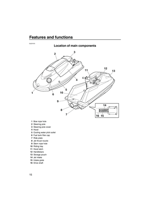
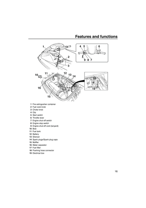
Maintenance and care
50
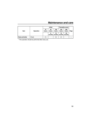
* This operation should be performed after every use.
Nuts and boltsCheck ŌĆö Item OperationInitial Thereafter every
Page 10
hours50
hours100
hours100
hours200
hours
6
months12
months12
months24
months
UF2F71E0.book Page 50 Thursday, April 10, 2008 11:47 AM
Page 58 of 76

Maintenance and care
51
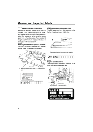
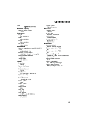
EJU34202Checking the fuel system
WARNING
EWJ00381
Leaking fuel can result in fire or explosion.
�Check for fuel leakage regularly.
�If any fuel leakage is found, the fuel sys-
tem must be repaired by a qualified me-
chanic. Improper repairs can make the
watercraft unsafe to operate.
Check the fuel system for leaks, cracks, and
malfunctions. If any problem is found, consult
a Yamaha dealer.
Check:
�Carburetor for leakage
�Fuel tank filler cap and seal for damage
�Fuel in fuel tank for water and dirt
�Fuel tank for damage, cracks, and leakage
�Fuel hoses and joints for damage, cracks,
and leakage
�Fuel filter for leakage
�Fuel cock for leakage
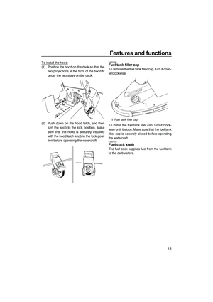
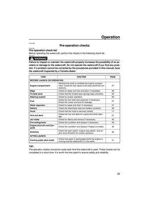
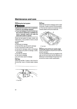
�Air vent check valve for leakageEJU34221Fuel filter
Check the fuel filter. If water or dirt is found in
the fuel filter, have a Yamaha dealer replace
it.
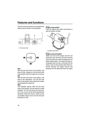
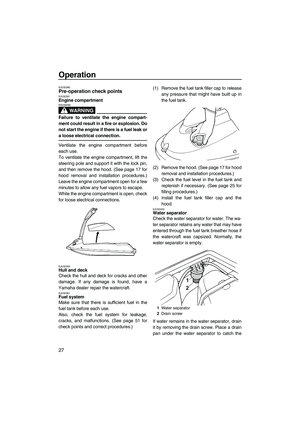
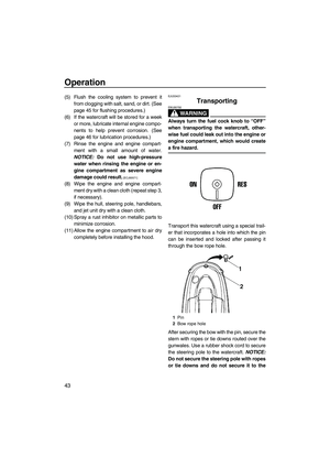
EJU34230Fuel tank
Check the fuel tank for leakage and for water
in the tank. If water is found in the fuel system,
or if the fuel tank needs to be cleaned, have a
Yamaha dealer service the watercraft.
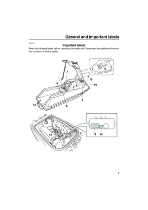
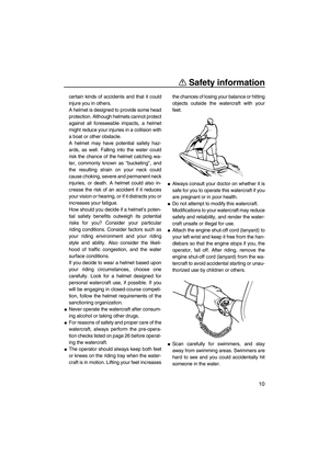
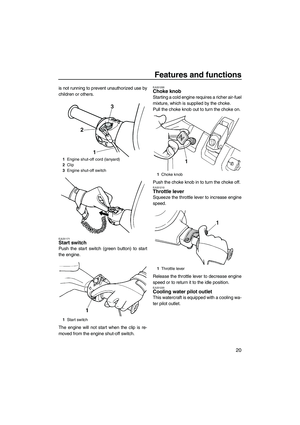
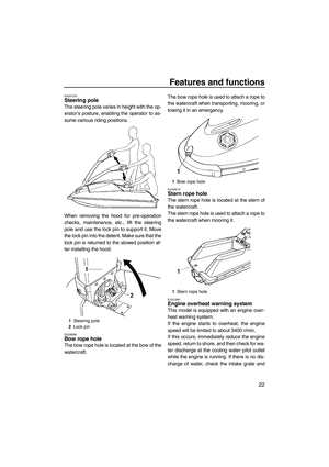
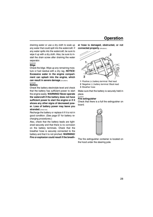
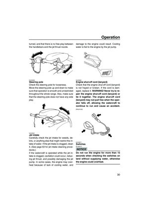
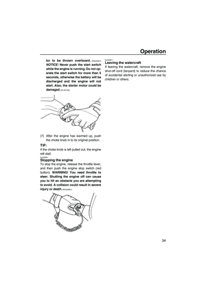
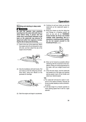
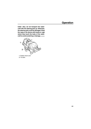
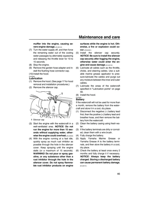
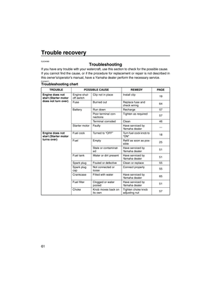
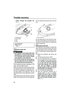
EJU34321Checking the jet thrust nozzle angle
Check the handlebars and jet thrust nozzle for
smooth operation.
Turn the handlebars as far as possible to the
right and left and check that the difference of
distances A and B between the jet thrust noz-
zle and the nozzle is within specification.
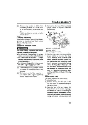
1Fuel filter
1Fuel tank
UF2F71E0.book Page 51 Thursday, April 10, 2008 11:47 AM
Page 59 of 76
Maintenance and care
52
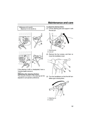
If the steering is stiff or misadjusted, have a
Yamaha dealer service it.
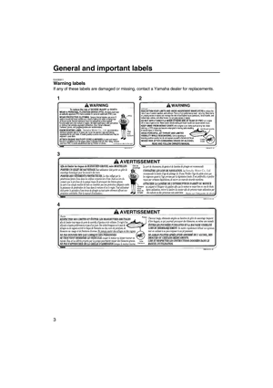
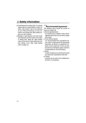
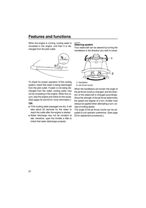
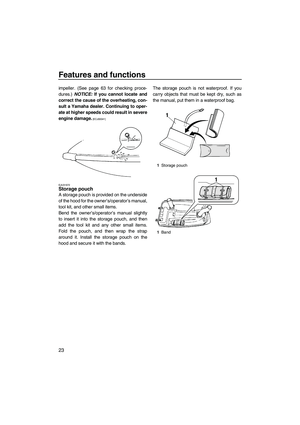
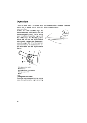
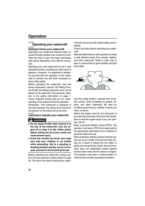
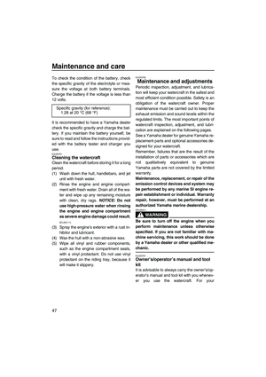
EJU34332Adjusting the steering friction
The amount of friction in the steering can be
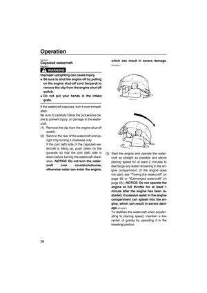
adjusted to suit operator preference.To adjust the steering friction:
(1) Lift the steering pole and support it with
the lock pin.
(2) Remove the four screws, and then re-
move the handlebar cover.
(3) Turn the handlebars so that the left han-
dlebar grip is facing down. Difference of A and B:
Maximum 5 mm (0.20 in)
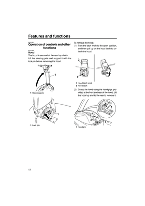
1Steering pole
2Lock pin
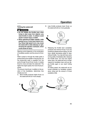
1Adjusting nut
2Locknut
UF2F71E0.book Page 52 Thursday, April 10, 2008 11:47 AM
Page 60 of 76
 Loosen the locknut.
(5) Tighten or loosen the adjusting nut until
the desired amount of friction is obtained.
(6) Hold the adjusting nut with one wrench
while tightening th")
Maintenance and care
53
(4) Loosen the locknut.
(5) Tighten or loosen the adjusting nut until
the desired amount of friction is obtained.
(6) Hold the adjusting nut with one wrench
while tightening the locknut with another
wrench.
(7) Install the handlebar cover and the four
screws.
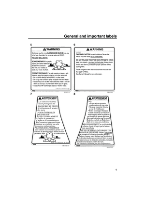
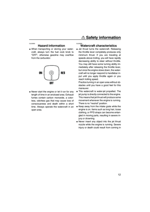
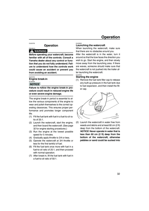
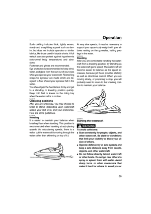
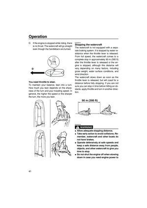
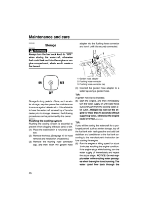
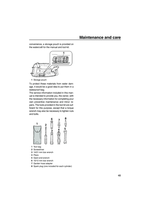
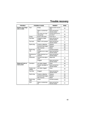
EJU31285Adjusting the jet thrust nozzle angle
The angle of the jet thrust nozzle can be ad-
justed to suit operator preference according to
the following procedure.
To change the steering cable pivot bolt posi-
tion:
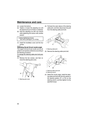
(1) Remove the two screws, and then re-
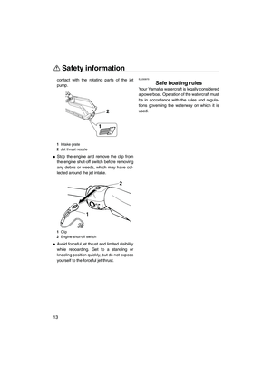
move the steering pole cover.(2) Pull back the outer sleeve of the steering
cable joint, and then disconnect the joint
from the steering cable pivot bolt.
(3) Remove the steering cable pivot bolt.
(4) Select the nozzle angle, install the steer-
ing cable pivot bolt with the lock washer in
the desired position (P1 or P2) on the
steering column, and then tighten it to the
specified torque. Locknut tightening torque:
29.0 Nm (2.96 kgf-m, 21.4 ft-lb)
1Steering pole cover
1Steering cable joint
1Steering cable pivot bolt
2Steering column
UF2F71E0.book Page 53 Thursday, April 10, 2008 11:47 AM
Page 61 of 76
 Connect the steering cable joint to the
steering cable pivot bolt.
(6) Install the steering pole cover, and t")
Maintenance and care
54
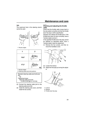
TIP:
The outermost hole in the steering column
cannot be used.
(5) Connect the steering cable joint to the
steering cable pivot bolt.
(6) Install the steering pole cover, and then
install the two screws.
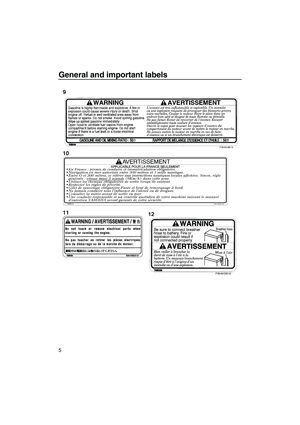
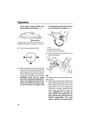
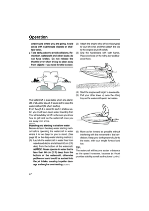
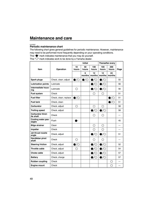
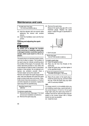
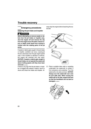
EJU34361Checking and adjusting the throttle
cable
Check that the throttle cable moves back to
the set position smoothly and that the throttle
lever free play is within specification.
Squeeze and release the throttle lever. If the
throttle lever does not return smoothly, have a
Yamaha dealer service it.
If the specified throttle lever free play cannot
be obtained as described below, have a
Yamaha dealer make the adjustment.
(1) Remove the four screws, and then re-
move the handlebar cover.
(2) Loosen the locknut.
(3) Adjust the free play by turning the adjust-
er.
1Nozzle angles
1Nozzle angles
2Steering cable pivot bolt positions
Standard steering cable pivot bolt posi-
tion:
P2
Tightening torque:
Steering cable pivot bolt:
5.4 Nm (0.55 kgf-m, 4.0 ft-lb)
1Locknut
2Adjuster
3Throttle lever free play
UF2F71E0.book Page 54 Thursday, April 10, 2008 11:47 AM
Page 62 of 76
 Hold the adjuster with one wrench while
tightening the locknut with another
wrench.
(5) Install the handlebar cover and the four
screws.
EJU34374Cleaning and adjusting the")
Maintenance and care
55
(4) Hold the adjuster with one wrench while
tightening the locknut with another
wrench.
(5) Install the handlebar cover and the four
screws.
EJU34374Cleaning and adjusting the spark
plugs
WARNING
EWJ00350
Be careful not to damage the insulator
when removing or installing a spark plug.
A damaged insulator could allow sparks to
escape, which could result in a fire or ex-
plosion.
The spark plug is an important engine compo-
nent and is easy to inspect. The condition of
the spark plug can indicate something about
the condition of the engine. For example, if the
center electrode porcelain is very white, this
could indicate an intake air leak or carburetion
problem in that cylinder. Do not attempt to di-
agnose any problems yourself. Have a
Yamaha dealer service the watercraft.
Remove and inspect the spark plugs periodi-
cally; heat and deposits will cause the spark
plugs to slowly break down and erode. If elec-
trode erosion becomes excessive, or if carbon
and other deposits are excessive, replace the
spark plug with the specified plug.
To remove a spark plug:
(1) Remove the hood. (See page 17 for hood
removal and installation procedures.)
(2) Remove the spark plug cap.(3) Remove the spark plug.
Measure the spark plug gap with a wire
thickness gauge. Replace the spark
plugs or adjust the gap to specification if
necessary.
To install a spark plug:
(1) Clean the gasket surface.
(2) Wipe any dirt from the threads of the
spark plug.
(3) Install the spark plug, and then tighten it
to the specified torque.
(4) Wipe off any water on the spark plug or
inside the spark plug cap, and then install
the cap. Push the spark plug cap down
until it is securely installed.
TIP:
If a torque wrench is not available when you
are installing a spark plug, a good estimate of
the correct torque is 1/4 turn to 1/2 turn past
finger tight using the spark plug wrench in-
cluded in the tool kit. Have the spark plug ad-
justed to the correct torque with a torque
wrench as soon as possible.
(5) Install the hood. Throttle lever free play:
7.0ŌĆō10.0 mm (0.28ŌĆō0.39 in)
Specified spark plug:
BR7HS
1Spark plug gap
Spark plug gap:
0.6ŌĆō0.7 mm (0.024ŌĆō0.028 in)
Spark plug tightening torque:
25.0 Nm (2.55 kgf-m, 18.4 ft-lb)
UF2F71E0.book Page 55 Thursday, April 10, 2008 11:47 AM
Page 63 of 76

�Choke cable (carburetor")
Maintenance and care
56
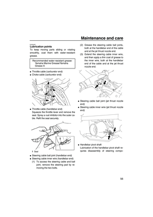
EJU34401Lubrication points
To keep moving parts sliding or rotating
smoothly, coat them with water-resistant
grease.
�Throttle cable (carburetor end)
�Choke cable (carburetor end)
�Throttle cable (handlebar end)
Squeeze the throttle lever and remove the
seal. Spray a rust inhibitor into the outer ca-
ble. Refit the seal securely.
�Steering cable ball joint (handlebar end)
�Steering cable inner wire (handlebar end)
(1) To access the steering cable and ball
joint, remove the steering pad by re-
moving the two bolts.(2) Grease the steering cable ball joints,
both at the handlebar end of the cable
and at the jet thrust nozzle end.
(3) Extend the steering cable inner wire,
and then apply a thin coat of grease to
the inner wire, both at the handlebar
end of the cable and at the jet thrust
nozzle end.
�Steering cable ball joint (jet thrust nozzle
end)
�Steering cable inner wire (jet thrust nozzle
end)
�Handlebar pivot shaft
Lubrication of the handlebar pivot shaft re-
quires disassembly of steering compo- Recommended water-resistant grease:
Yamaha Marine Grease/Yamaha
Grease A
1Seal
UF2F71E0.book Page 56 Thursday, April 10, 2008 11:47 AM
Page 64 of 76

Maintenance and care
57
nents. Have a Yamaha dealer lubricate the
handlebar pivot shaft.
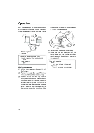
�Intermediate housing
Fill the intermediate housing with water-re-
sistant grease through the grease nipple
using a grease gun.
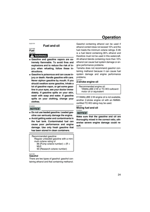
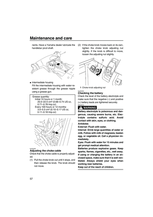
EJU34440Adjusting the choke cable
Check that the choke cable is properly adjust-
ed.
(1) Pull the choke knob out until it stops, and
then release the knob. The knob should
not move.(2) If the choke knob moves back on its own,
tighten the choke knob adjusting nut
slightly. If the knob is difficult to move,
loosen the adjusting nut slightly.
EJU34452Checking the battery
Check the level of the battery electrolyte and
make sure that the negative (ŌĆō) and positive
(+) battery leads are tightened securely.
WARNING
EWJ00791
Battery electrolyte is poisonous and dan-
gerous, causing severe burns, etc. Elec-
trolyte contains sulfuric acid. Avoid
contact with skin, eyes, or clothing.
Antidotes
External: Flush with water.
Internal: Drink large quantities of water or
milk. Follow with milk of magnesia, beaten
egg, or vegetable oil. Call a physician im-
mediately.
Eyes: Flush with water for 15 minutes and
get prompt medical attention.
Batteries produce explosive gases. Keep
sparks, flames, cigarettes, etc., well away.
If using or charging the battery in an en-
closed space, make sure that it is well ven-
tilated. Always shield your eyes when
working near batteries.
Keep out of the reach of children.
Grease quantity:
Initial 10 hours or 1 month:
20.0ŌĆō22.0 cm┬│ (0.68ŌĆō0.74 US oz,
0.71ŌĆō0.78 Imp.oz)
Every 100 hours or 12 months:
3.0ŌĆō5.0 cm┬│ (0.10ŌĆō0.17 US oz,
0.11ŌĆō0.18 Imp.oz)
1Choke knob adjusting nut
UF2F71E0.book Page 57 Thursday, April 10, 2008 11:47 AM