Page 57 of 106

Operation
50
EJU31980
Pre-operation checks EJU31991Pre-operation check list
Before operating this watercraft, perform the checks in the following check list.
WARNING
EWJ00411
Failure to inspect or maintain the watercraft properly increases the possibility of an ac-
cident or damage to the watercraft. Do not operate the watercraft if you find any prob-
lem. If a problem cannot be corrected by the procedures provided in this manual, have
the watercraft inspected by a Yamaha dealer.
ITEM ROUTINE PAGE
BEFORE LAUNCH OR OPERATION
Engine compartmentRemove the seats to ventilate the engine compart-
ment. Check for fuel vapors and loose electrical con-
nections.52
BilgeCheck for water and fuel and drain if necessary. 54
Stern drain plugsCheck for proper installation. 54
Throttle leverCheck that the throttle lever springs back smoothly. 55
Steering systemCheck for proper operation.
Check that the handlebars are locked in place.56
Shift lever and reverse gate Check for proper operation. 56
QSTSCheck for proper operation. 57
Fuel and oilCheck the fuel and oil levels and replenish if neces-
sary.
Check the hoses and tanks for leakage.52, 52
Water separatorCheck for water and drain if necessary. 53
BatteryCheck the electrolyte level and battery condition. 54
HoodCheck that the hood is securely closed. 26
Front and rear seatsCheck that the seats are securely installed. 25
Hull and deckCheck the hull and deck for cracks and other dam-
age.52
Jet intakeCheck for debris and remove if necessary. 58
Fire extinguisherCheck the condition and replace if necessary. 55
Engine shut-off cord (lan-
yard)Check the condition and replace if frayed or broken. 58
SwitchesCheck the start switch, engine stop switch, and en-
gine shut-off switch for proper operation.58
AFTER LAUNCH
Cooling water pilot outletCheck that water is discharged while the engine is
running and the watercraft is in the water.59
Multifunction information
centerCheck for warning indications and proper operation. 59
UF2H70E0.book Page 50 Thursday, January 15, 2009 10:49 AM
Page 58 of 106
Operation
51
TIP:
Pre-operation checks should be made each time the watercraft is used. These checks can be
completed in a short time. It is worth the time spent to ensure safety and reliability.
UF2H70E0.book Page 51 Thursday, January 15, 2009 10:49 AM
Page 59 of 106

Operation
52
EJU32280Pre-operation check points EJU32331Engine compartment
WARNING
EWJ00460
Failure to ventilate the engine compart-
ment could result in a fire or explosion. Do
not start the engine if there is a fuel leak or
a loose electrical connection.
Ventilate the engine compartment before
each use.
To ventilate the engine compartment, remove
the seats. (See page 25 for seat removal and
installation procedures.) Leave the engine
compartment open for a few minutes to allow
any fuel vapors to escape.
While the engine compartment is open, check
for loose electrical connections.
EJU32350Hull and deck
Check the hull and deck for cracks and other
damage. If any damage is found, have a
Yamaha dealer repair the watercraft.
EJU36871Fuel level
Make sure that there is sufficient fuel in the
fuel tank before each use.
Also, check the fuel system for leakage,
cracks, and malfunctions. (See page 79 for
check points and correct procedures.)
(1) Open the hood and remove the fuel tank
filler cap to release any pressure thatmight have built up in the fuel tank. (See
page 26 for hood opening and closing
procedures.)
(2) Remove the seats. (See page 25 for seat
removal and installation procedures.)
(3) Check the fuel level in the fuel tank and
replenish if necessary. (See page 48 for
filling procedures.)
(4) Install the fuel tank filler cap, and then
close the hood and install the seats.
EJU36882Engine oil level
Check the engine oil level before each use.
WARNING
EWJ00340
Engine oil is extremely hot immediately af-
ter the engine is turned off. Coming in con-
tact with or getting any engine oil on your
clothes could result in burns.
NOTICE
ECJ01001
Make sure that debris and water do not en-
ter the oil filler hole. Debris and water in
the engine oil can cause serious engine
damage.
To check the engine oil level:
(1) Place the watercraft in a precisely level
position on land with the engine stopped.
TIP:
If the engine was running, allow the engine oil
to settle by waiting 5 minutes or more before
checking the oil level.
(2) Remove the seats. (See page 25 for seat
removal and installation procedures.)
(3) Remove the dipstick, wipe it clean, and
then insert it back into the dipstick tube
completely. Remove the dipstick again
and check that the engine oil level is be-
UF2H70E0.book Page 52 Thursday, January 15, 2009 10:49 AM
Page 60 of 106
 If the engine oil level is below the mini-
mum level mark, perform steps 5–7 to
add enough oil so that the oil level is be-
tween the mini")
Operation
53
tween the minimum and maximum level
marks.
(4) If the engine oil level is below the mini-
mum level mark, perform steps 5–7 to
add enough oil so that the oil level is be-
tween the minimum and maximum level
marks on the dipstick. If the engine oil lev-
el is significantly above the maximum lev-
el mark, have a Yamaha dealer service
the watercraft.(5) Remove the engine oil filler cap.
(6) Pour engine oil into the filler hole. Wait
approximately 5 minutes until the engine
oil settles.
TIP:
The difference between the minimum and
maximum level marks on the dipstick is equal
to approximately 1 liter of engine oil.
(7) Repeat steps 3–6 until the engine oil is at
the proper level.
(8) Install the engine oil filler cap, and then
install the seats.
EJU32420Water separator
Check the water separator for water. The wa-
ter separator retains any water that may have
entered through the fuel tank breather hose if
the watercraft was capsized. Normally, the
water separator is empty.
1Dipstick
1Maximum level mark
2Minimum level mark
1
12
1Engine oil filler cap
1Water separator
2Drain screw
1
2
1
UF2H70E0.book Page 53 Thursday, January 15, 2009 10:49 AM
Page 61 of 106

Operation
54
If water remains in the water separator, drain
it by removing the drain screw. Place a drain
pan under the water separator to catch the
draining water or use a dry cloth to soak up
any water that could spill into the watercraft. If
any water spills into the watercraft, be sure to
wipe it up with a dry cloth. Also, be sure to in-
stall the drain screw after draining the water
separator.
EJU32452Bilge
Check the bilge for moisture and fuel residue.
NOTICE: Excessive water in the engine
compartment can splash into the engine,
which can result in severe damage.
[ECJ00341]
This watercraft is equipped with a convention-
al jet vacuum bilge draining system and an
electric bilge draining system. The electric
bilge draining system is operated when the
engine is running. When excess water reach-
es the water inlet of the electric bilge pump,
the water is discharged from the electric bilge
pilot outlet at the stern.
A small quantity of water will remain in the
bilge and should be drained manually. To
drain any residual water, beach the watercraft
and perform the following procedure.
To drain water from the bilge:
(1) Remove the stern drain plugs.
(2) Raise the bow of the watercraft until the
water drains.(3) After the water has drained, wipe the
bilge with dry rags to make sure that it is
thoroughly dry.
(4) Install the stern drain plugs. NOTICE:
Before installing the stern drain plugs,
clean the drain plug threads to remove
any foreign materials, such as dirt or
sand. Otherwise, the stern drain plugs
could be damaged, allowing water to
enter the engine compartment. Make
sure that the stern drain plugs are
tightened securely before launching
the watercraft. Otherwise, water may
flood the engine compartment and
cause the watercraft to submerge.
[ECJ00361]
EJU32472
Stern drain plugs
Check the stern drain plugs for proper instal-
lation.
EJU32482Battery
Check the battery electrolyte level and check
that the battery has sufficient power to start
the engine easily. WARNING! Never operate
the watercraft if the battery does not have
sufficient power to start the engine or if it
shows any other signs of decreased pow-
er. Loss of battery power may leave you
stranded.
[EWJ01240]
1Electric bilge pilot outlet
1
1Stern drain plugs
1
UF2H70E0.book Page 54 Thursday, January 15, 2009 10:49 AM
Page 62 of 106

Also, check that the battery leads are tight-
ened securely and that")
Operation
55
Recharge the battery or replace it if it is not in
good condition. (See page 86 for battery re-
charging procedures.)
Also, check that the battery leads are tight-
ened securely and that there is no corrosion
on the battery terminals. Check that the
breather hose is securely connected to the
battery and that it is not pinched. WARNING!
Fire or explosion could result if the breath-
er hose is damaged, obstructed, or not
connected properly.
[EWJ00451]
Make sure that the battery is securely held in
place.
EJU32581Fire extinguisher
Check that there is a full fire extinguisher on
board.
The fire extinguisher container is located in
the seat storage compartment.To open the fire extinguisher container, turn
the cap counterclockwise.
To close the fire extinguisher container, insert
the fire extinguisher into the container, and
then install the cap and tighten it securely.
To check the fire extinguisher, see the instruc-
tions supplied by the fire extinguisher manu-
facturer. Always keep the fire extinguisher in
the fire extinguisher container.
Always carry a fire extinguisher on board. A
fire extinguisher is not standard equipment
with this watercraft. If you do not have one,
contact a Yamaha dealer or a fire extinguisher
dealer to obtain one meeting the proper spec-
ifications.EJU32591Throttle lever
Check the throttle lever for proper operation.
Squeeze and release the throttle lever several
times to make sure that there is no hesitation
in its travel. It should be smooth over the com-
1Positive (+) battery terminal: Red lead
2Negative (–) battery terminal: Black lead
3Breather hose
3
1
2
1Fire extinguisher container
2Fire extinguisher container cap
UF2H70E0.book Page 55 Thursday, January 15, 2009 10:49 AM
Page 63 of 106
Operation
56
plete range and spring back to the idle posi-
tion when released.
EJU32611Steering system
Check the handlebars for looseness.
Turn the handlebars as far as possible to the
right and left to make sure that operation is
smooth and unrestricted throughout the
whole range. Also, make sure that the jet
thrust nozzle moves as the handlebars are
turned, and that there is no free play between
the handlebars and the jet thrust nozzle.
Push the handlebars back and forth to check
that the tilt lever and handlebars are locked inplace. (See “Tilt lever” on page 30 for more in-
formation.)EJU36581Shift lever and reverse gate
WARNING
EWJ00031
Do not touch the reverse gate while the
shift lever is being operated, otherwise
you could be pinched.
Check the shift lever and reverse gate for
proper operation.
Make sure that the reverse gate goes down
completely when the shift lever is pulled up.
1Tilt lever
UF2H70E0.book Page 56 Thursday, January 15, 2009 10:49 AM
Page 64 of 106
Operation
57
Also, make sure that the reverse gate goes up
completely when the shift lever is pushed
down.
EJU32641Quick Shift Trim System (QSTS)
Operate the QSTS selector lock lever and the
QSTS selector several times to check that
they operate properly.
(1) Squeeze the QSTS selector lock lever
and check that it returns smoothly to its
original position when released.(2) Check that the QSTS selector turns
smoothly when the lever is squeezed and
check that the selector locks in place at
each position when the lever is released.
(3) Check that the angle of the jet thrust noz-
zle changes when the QSTS selector is
shifted from neutral to bow up or bow
down.
If the mechanism does not work properly,
have a Yamaha dealer service it.
UF2H70E0.book Page 57 Thursday, January 15, 2009 10:49 AM
 1
1 2
2 3
3 4
4 5
5 6
6 7
7 8
8 9
9 10
10 11
11 12
12 13
13 14
14 15
15 16
16 17
17 18
18 19
19 20
20 21
21 22
22 23
23 24
24 25
25 26
26 27
27 28
28 29
29 30
30 31
31 32
32 33
33 34
34 35
35 36
36 37
37 38
38 39
39 40
40 41
41 42
42 43
43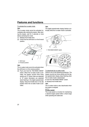 44
44 45
45 46
46 47
47 48
48 49
49 50
50 51
51 52
52 53
53 54
54 55
55 56
56 57
57 58
58 59
59 60
60 61
61 62
62 63
63 64
64 65
65 66
66 67
67 68
68 69
69 70
70 71
71 72
72 73
73 74
74 75
75 76
76 77
77 78
78 79
79 80
80 81
81 82
82 83
83 84
84 85
85 86
86 87
87 88
88 89
89 90
90 91
91 92
92 93
93 94
94 95
95 96
96 97
97 98
98 99
99 100
100 101
101 102
102 103
103 104
104 105
105


Operate the QSTS selector lock lever and the
QSTS sel")