Page 73 of 108

PERIODIC MAINTENANCE AND ADJUSTMENT
6-15
6 To change the final gear oil
1. Place the vehicle on a level sur-
face.
2. Place an oil pan under the final
gear case to collect the used oil.
3. Remove the oil filler bolt and drain
bolt to drain the oil from the final
gear case.
4. Install the final gear oil drain bolt,
and then tighten it to the specified
torque.
5. Refill with the recommended final
gear oil to the brim of the filler hole.6. Install the oil filler bolt, and then
tighten it to the specified torque.
7. Check the final gear case for oil
leakage. If oil is leaking, check for
the cause.
EAU20070
Coolant The coolant level should be checked
before each ride. In addition, the cool-
ant must be changed at the intervals
specified in the periodic maintenance
and lubrication chart.
EAU40153
To check the coolant level
1. Place the vehicle on the center-
stand.TIP�
The coolant level must be checked
on a cold engine since the level
varies with engine temperature.
�
Make sure that the vehicle is posi-
tioned straight up when checking
the coolant level. A slight tilt to theside can result in a false reading.
2. Check the coolant level in the cool-
ant reservoir.
TIPThe coolant should be between theminimum and maximum level marks.
Tightening torque:
Final gear oil filler bolt:
23 Nm (2.3 m·kgf, 17 ft·lbf)
Tightening torque:
Final gear oil drain bolt:
23 Nm (2.3 m·kgf, 17 ft·lbf)
Recommended final gear oil:
Shaft drive gear oil (Part No.: 9079E-
SH001-00)
Oil quantity:
0.20 L (0.21 US qt, 0.18 Imp.qt)
Tightening torque:
Final gear oil filler bolt:
23 Nm (2.3 m·kgf, 17 ft·lbf)
U2D2E3E0.book Page 15 Friday, September 26, 2008 3:51 PM
Page 74 of 108

PERIODIC MAINTENANCE AND ADJUSTMENT
6-16
63. If the coolant is at or below the
minimum level mark, remove the
reservoir cap.
4. Add coolant or distilled water to
raise the coolant to the maximum
level mark, install the coolant res-ervoir cap. WARNING! Remove
only the coolant reservoir cap.
Never attempt to remove the ra-
diator cap when the engine is
hot.
[EWA15161]
NOTICE: If coolant is
not available, use distilled water
or soft tap water instead. Do not
use hard water or salt water
since it is harmful to the engine.
If water has been used instead
of coolant, replace it with cool-
ant as soon as possible, other-
wise the cooling system will not
be protected against frost and
corrosion. If water has been
added to the coolant, have a
Yamaha dealer check the anti-
freeze content of the coolant as
soon as possible, otherwise the
effectiveness of the coolant will
be reduced. [ECA10472]EAU33031
Changing the coolant
The coolant must be changed at the in-
tervals specified in the periodic mainte-
nance and lubrication chart. Have a
Yamaha dealer change the coolant.
WARNING! Never attempt to remove
the radiator cap when the engine is
hot.
[EWA10381]
1. Maximum level mark
2. Minimum level mark
1. Coolant reservoir cap
Coolant reservoir capacity (up to the
maximum level mark):
0.25 L (0.26 US qt, 0.22 Imp.qt)
U2D2E3E0.book Page 16 Friday, September 26, 2008 3:51 PM
Page 75 of 108
PERIODIC MAINTENANCE AND ADJUSTMENT
6-17
6
EAU40371
Air filter element The air filter element should be cleaned
or replaced at the intervals specified in
the periodic maintenance and lubrica-
tion chart. Have a Yamaha dealer clean
or replace the air filter element.
EAU44734
Checking the engine idling
speed Check the engine idling speed and, if
necessary, have it corrected by a
Yamaha dealer.
EAU21382
Checking the throttle cable
free play The throttle cable free play should mea-
sure 3.0–5.0 mm (0.12–0.20 in) at the
throttle grip. Periodically check the
throttle cable free play and, if neces-
sary, have a Yamaha dealer adjust it.
Engine idling speed:
1000–1100 r/min
1. Throttle cable free play
U2D2E3E0.book Page 17 Friday, September 26, 2008 3:51 PM
Page 76 of 108

PERIODIC MAINTENANCE AND ADJUSTMENT
6-18
6
EAU21401
Valve clearance The valve clearance changes with use,
resulting in improper air-fuel mixture
and/or engine noise. To prevent this
from occurring, the valve clearance
must be adjusted by a Yamaha dealer
at the intervals specified in the periodic
maintenance and lubrication chart.
EAU21772
Tires To maximize the performance, durabil-
ity, and safe operation of your motor-
cycle, note the following points
regarding the specified tires.
Tire air pressure
The tire air pressure should be checked
and, if necessary, adjusted before each
ride.
WARNING
EWA10501
Operation of this vehicle with im-
proper tire pressure may cause se-
vere injury or death from loss of
control.�
The tire air pressure must be
checked and adjusted on cold
tires (i.e., when the temperature
of the tires equals the ambient
temperature).
�
The tire air pressure must be ad-
justed in accordance with the
riding speed and with the total
weight of rider, passenger, car-
go, and accessories approvedfor this model.
WARNING
EWA10511
Never overload your vehicle. Opera-
tion of an overloaded vehicle couldcause an accident.Tire air pressure (measured on cold
tires):
0–90 kg (0–198 lb):
Front:
270 kPa (2.70 kgf/cm², 39 psi)
Rear:
290 kPa (2.90 kgf/cm², 42 psi)
90–208 kg (198–459 lb):
Front:
270 kPa (2.70 kgf/cm², 39 psi)
Rear:
290 kPa (2.90 kgf/cm², 42 psi)
High-speed riding:
Front:
270 kPa (2.70 kgf/cm², 39 psi)
Rear:
290 kPa (2.90 kgf/cm², 42 psi)
Maximum load*:
208 kg (459 lb)
* Total weight of rider, passenger, car-
go and accessories
U2D2E3E0.book Page 18 Friday, September 26, 2008 3:51 PM
Page 77 of 108

PERIODIC MAINTENANCE AND ADJUSTMENT
6-19
6 Tire inspection
The tires must be checked before each
ride. If the center tread depth reaches
the specified limit, if the tire has a nail or
glass fragments in it, or if the sidewall is
cracked, have a Yamaha dealer re-
place the tire immediately.
TIPThe tire tread depth limits may differ
from country to country. Always complywith the local regulations.
WARNING
EWA10470
�
Have a Yamaha dealer replace
excessively worn tires. Besides
being illegal, operating the vehi-
cle with excessively worn tires
decreases riding stability and
can lead to loss of control.
�
The replacement of all wheel
and brake related parts, includ-
ing the tires, should be left to a
Yamaha dealer, who has the
necessary professional knowl-edge and experience.
Tire informationThis motorcycle is equipped with cast
wheels and tubeless tires with valves.
WARNING
EWA10481
�
The front and rear tires should
be of the same make and de-
sign, otherwise the handling
characteristics of the motor-
cycle may be different, which
could lead to an accident.
�
Always make sure that the valve
caps are securely installed to
prevent air pressure leakage.
�
Use only the tire valves and
valve cores listed below to
avoid tire deflation during ahigh-speed ride.
After extensive tests, only the tires list-
ed below have been approved for this
model by Yamaha Motor Co., Ltd.
1. Tire sidewall
2. Tire tread depthMinimum tire tread depth (front and
rear):
1.6 mm (0.06 in)
1. Tire air valve
2. Tire air valve core
3. Tire air valve cap with seal
U2D2E3E0.book Page 19 Friday, September 26, 2008 3:51 PM
Page 78 of 108

PERIODIC MAINTENANCE AND ADJUSTMENT
6-20
6
WARNING
EWA10600
This motorcycle is fitted with super-
high-speed tires. Note the following
points in order to make the most ef-
ficient use of these tires.�
Use only the specified replace-
ment tires. Other tires may run
the danger of bursting at super
high speeds.
�
Brand-new tires can have a rela-
tively poor grip on certain road
surfaces until they have been“broken in”. Therefore, it is ad-
visable before doing any high-
speed riding to ride conserva-
tively for approximately 100 km
(60 mi) after installing a new tire.
�
The tires must be warmed up
before a high-speed run.
�
Always adjust the tire air pres-
sure according to the operatingconditions.
EAU21960
Cast wheels To maximize the performance, durabil-
ity, and safe operation of your vehicle,
note the following points regarding the
specified wheels.�
The wheel rims should be checked
for cracks, bends or warpage be-
fore each ride. If any damage is
found, have a Yamaha dealer re-
place the wheel. Do not attempt
even the smallest repair to the
wheel. A deformed or cracked
wheel must be replaced.
�
The wheel should be balanced
whenever either the tire or wheel
has been changed or replaced. An
unbalanced wheel can result in
poor performance, adverse han-
dling characteristics, and a short-
ened tire life.
�
Ride at moderate speeds after
changing a tire since the tire sur-
face must first be “broken in” for it
to develop its optimal characteris-
tics.
Front tire:
Size:
120/70 ZR17M/C (58W)
Manufacturer/model:
METZELER/Roadtec Z6G
BRIDGESTONE/BT021F F
Rear tire:
Size:
180/55 ZR17M/C (73W)
Manufacturer/model:
METZELER/Roadtec Z6C
BRIDGESTONE/BT021R F
FRONT and REAR:
Tire air valve:
TR412
Va l ve c o r e :
#9100 (original)
U2D2E3E0.book Page 20 Friday, September 26, 2008 3:51 PM
Page 79 of 108

PERIODIC MAINTENANCE AND ADJUSTMENT
6-21
6
EAU40620
YCC-S clutch This model is equipped with a hydraulic
clutch, therefore, it is necessary to
check the YCC-S clutch fluid level and
check the hydraulic system for leakage
before each ride. If the YCC-S clutch
plates wear out, shifting becomes
rough or clutch slippage will occur,
causing poor acceleration. If any of the
above occurs, have a Yamaha dealer
check the YCC-S clutch.
EAU36502
Rear brake light switch The rear brake light, which is activated
by the brake pedal, should come on just
before braking takes effect. If neces-
sary, have a Yamaha dealer adjust the
brake light switch.
EAU22390
Checking the front and rear
brake pads The front and rear brake pads must be
checked for wear at the intervals spec-
ified in the periodic maintenance and
lubrication chart.
EAU43431
Front brake pads
The front brake calipers are equipped
with two sets of brake pads.
Each front brake pad is provided with a
wear indicator groove, which allows
you to check the brake pad wear with-
out having to disassemble the brake.
To check a brake pad for wear, check
its wear indicator groove. If a brake pad
has worn to the point that the wear indi-1. Brake pad wear indicator groove
1
1
U2D2E3E0.book Page 21 Friday, September 26, 2008 3:51 PM
Page 80 of 108

PERIODIC MAINTENANCE AND ADJUSTMENT
6-22
6cator groove has almost disappeared,
have a Yamaha dealer replace the
brake pads as a set.
EAU22500
Rear brake pads
Check each rear brake pad for damage
and measure the lining thickness. If a
brake pad is damaged or if the lining
thickness is less than 0.8 mm (0.03 in),
have a Yamaha dealer replace the
brake pads as a set.
EAU40591
Checking the brake and
YCC-S clutch fluid levels Front brake
Rear brakeYCC-S clutch
Insufficient brake fluid may allow air to
enter the brake or YCC-S clutch sys-
tems, possibly causing them to become
ineffective.
Before riding, check that the brake fluid
is above the minimum level mark and
replenish if necessary. A low brake fluid
level may indicate worn brake pads
and/or brake system leakage. If the
brake fluid level is low, be sure to check
the brake pads for wear and the brake
system for leakage.
TIP�
The rear brake fluid reservoir is lo-
cated behind panel C. (See page
6-7.)
1. Lining thickness
1. Minimum level mark
1. Minimum level mark
1. Minimum level mark
U2D2E3E0.book Page 22 Friday, September 26, 2008 3:51 PM
 1
1 2
2 3
3 4
4 5
5 6
6 7
7 8
8 9
9 10
10 11
11 12
12 13
13 14
14 15
15 16
16 17
17 18
18 19
19 20
20 21
21 22
22 23
23 24
24 25
25 26
26 27
27 28
28 29
29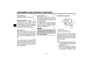 30
30 31
31 32
32 33
33 34
34 35
35 36
36 37
37 38
38 39
39 40
40 41
41 42
42 43
43 44
44 45
45 46
46 47
47 48
48 49
49 50
50 51
51 52
52 53
53 54
54 55
55 56
56 57
57 58
58 59
59 60
60 61
61 62
62 63
63 64
64 65
65 66
66 67
67 68
68 69
69 70
70 71
71 72
72 73
73 74
74 75
75 76
76 77
77 78
78 79
79 80
80 81
81 82
82 83
83 84
84 85
85 86
86 87
87 88
88 89
89 90
90 91
91 92
92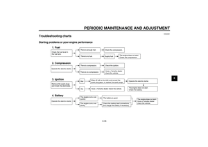 93
93 94
94 95
95 96
96 97
97 98
98 99
99 100
100 101
101 102
102 103
103 104
104 105
105 106
106 107
107