Page 25 of 108
 or when stopped at trafficsignals, railroad crossings")
INSTRUMENT AND CONTROL FUNCTIONS
3-11
3
�
The accuracy of the temperature
reading may be affected when
riding slowly (approximately under
20 km/h) or when stopped at trafficsignals, railroad crossings, etc.
Instantaneous fuel consumption mode
The instantaneous fuel consumption
display can be set to either “km/L” or
“L/100 km”.�
When the display is set to “km/L”,
the distance that can be traveled
on 1.0 L of fuel under the current
riding conditions is shown.
�
When the display is set to “L/100
km”, the amount of fuel necessary
to travel 100 km under the current
riding conditions is shown.
TIP�
To switch between the two instan-
taneous fuel consumption dis-
plays, push the reset button for 1
second when either display is
shown.
�
If traveling at speeds under 10km/h, “_ _._” will be displayed.
Average fuel consumption mode
This display shows the average fuel
consumption since it was last reset.The average fuel consumption display
can be set to either “AV_ _._ km/L” or
“AV_ _._ L/100 km”.
When the average fuel consumption
mode is selected, the display flashes
for five seconds, and then, depending
on the unit set, “AV_ _._ km/L” (aver-
age distance that can be traveled using
1.0 L of fuel) or “AV_ _._ L/100 km” (av-
erage amount of fuel necessary to trav-
el 100 km) is displayed.
To reset the average fuel consumption
display, push the reset button to select
the mode again, and then push the re-
set button for 1 second while the dis-
play is flashing.
TIP�
To switch between the two aver-
age fuel consumption displays,
push the reset button for 1 second
when either display is shown.
�
After resetting an average fuel
consumption display, “_ _._” will
be shown for that display until thevehicle has traveled 1 km.
1. Instantaneous fuel consumption
1. Average fuel consumption
U2D2E3E0.book Page 11 Friday, September 26, 2008 3:51 PM
Page 26 of 108

INSTRUMENT AND CONTROL FUNCTIONS
3-12
3
NOTICE
ECA15472
If there is a malfunction, “– –.–” will
be displayed. Have a Yamaha dealercheck the vehicle.
Ambient temperature, instanta-
neous fuel consumption and aver-
age fuel consumption modes (for
the UK only)
Push the reset button to switch the dis-
play between the ambient temperature
mode “Air”, the instantaneous fuel con-sumption mode “MPG” and the aver-
age fuel consumption mode “AV_ _._
MPG” in the following order:
Air → MPG → AV_ _._ MPG → Air
Ambient temperature mode
This display shows the ambient tem-
perature from –9 °C to 50 °C in 1 °C in-
crements. The temperature displayed
may vary from the ambient tempera-
ture.TIP�
If the ambient temperature falls be-
low –9 °C, a lower temperature
than –9 °C will not be displayed.
�
If the ambient temperature climbs
above 50 °C, a higher temperature
than 50 °C will not be displayed.
�
The accuracy of the temperature
reading may be affected when
riding slowly [approximately under
20 km/h (12.5 mi/h)] or when
stopped at traffic signals, railroadcrossings, etc.
Instantaneous fuel consumption mode
This display shows the distance that
can be traveled on 1.0 Imp.gal of fuel
under the current riding conditions.
1. Ambient temperature/instantaneous fuel
consumption/average fuel consumption
2. Select button
3. Reset button
1. Ambient temperature
1. Instantaneous fuel consumption
U2D2E3E0.book Page 12 Friday, September 26, 2008 3:51 PM
Page 27 of 108
, “_ _._” will be displayed.
Average fuel consumption modeThis display shows the average fuel
consumption s")
INSTRUMENT AND CONTROL FUNCTIONS
3-13
3
TIPIf traveling at speeds under 10 km/h(6.0 mi/h), “_ _._” will be displayed.
Average fuel consumption modeThis display shows the average fuel
consumption since it was last reset.
When the average fuel consumption
mode is selected, the display flashes
for five seconds, and then “AV_ _._
MPG” (average distance that can be
traveled using 1.0 Imp.gal of fuel) is
displayed.
TIP�
To reset the average fuel con-
sumption display, push the reset
button to select the mode again,
and then push the reset button for
1 second while the display is flash-
ing.
�
After resetting the average fuel
consumption display, “_ _._” will
be shown for that display until thevehicle has traveled 1 km (0.6 mi).
NOTICE
ECA15472
If there is a malfunction, “– –.–” will
be displayed. Have a Yamaha dealercheck the vehicle.Self-diagnosis device
This model is equipped with a self-diag-
nosis device for various electrical cir-
cuits.
If a problem is detected in any of those
circuits, the multi-function display will
indicate an error code.
If the multi-function display indicates
such an error code, note the code num-
ber, and then have a Yamaha dealer
check the vehicle.
1. Average fuel consumption
1. Error code display
2. Immobilizer system indicator light
U2D2E3E0.book Page 13 Friday, September 26, 2008 3:51 PM
Page 28 of 108

INSTRUMENT AND CONTROL FUNCTIONS
3-14
3
NOTICE
ECA11790
If the multi-function display indi-
cates an error code, the vehicle
should be checked as soon as pos-
sible in order to avoid engine dam-age.
The self-diagnosis device also detects
problems in the immobilizer system cir-
cuits.
If a problem is detected in the immobi-
lizer system circuits, the immobilizer
system indicator light will flash and the
multi-function display will indicate an
error code when the key is turned to
“ON”.TIPIf the multi-function display indicates er-
ror code 52, this could be caused by
transponder interference. If this errorappears, try the following.
1. Use the code re-registering key to
start the engine.TIPMake sure there are no other immobi-
lizer keys close to the main switch, and
do not keep more than one immobilizerkey on the same key ring! Immobilizer
system keys may cause signal interfer-
ence, which may prevent the engine
from starting.
2. If the engine starts, turn it off, and
try starting the engine with the
standard keys.
3. If one or both of the standard keys
do not start the engine, take the
vehicle, the code re-registering
key and both standard keys to a
Yamaha dealer and have the stan-
dard keys re-registered.
If the multi-function display indicates
any error codes, note the code number,
and then have a Yamaha dealer check
the vehicle.
EAU12331
Anti-theft alarm (optional) This model can be equipped with an
optional anti-theft alarm by a Yamaha
dealer. Contact a Yamaha dealer for
more information.
U2D2E3E0.book Page 14 Friday, September 26, 2008 3:51 PM
Page 29 of 108

INSTRUMENT AND CONTROL FUNCTIONS
3-15
3
EAU12347
Handlebar switches LeftRight
EAU12380
Pass switch“”
Press this switch to flash the head-
lights.
EAU12400
Dimmer switch“/”
Set this switch to“” for the high
beam and to“” for the low beam.
EAU12460
Turn signal switch“/”
To signal a right-hand turn, push this
switch to“”. To signal a left-hand
turn, push this switch to“”. When re-
leased, the switch returns to the centerposition. To cancel the turn signal
lights, push the switch in after it has re-
turned to the center position.
EAU12493
Windshield position adjusting
switch“”
To move the windshield up, push this
switch in direction (a). To move the
windshield down, push the switch in di-
rection (b).TIPWhen the key is turned to “OFF”, the
windshield will automatically return tothe lowest position.
1. Pass switch“”
2. Windshield position adjusting switch“”
3. Dimmer switch“/”
4. Turn signal switch“/”
5. Horn switch“”
6. Hand shift control switch
1. Engine stop switch“/”
2. Hazard switch“”
3. Start switch“”
1. Windshield position adjusting switch“”
U2D2E3E0.book Page 15 Friday, September 26, 2008 3:51 PM
Page 30 of 108

INSTRUMENT AND CONTROL FUNCTIONS
3-16
3
EAU12500
Horn switch“”
Press this switch to sound the horn.
EAU12660
Engine stop switch“/”
Set this switch to“” before starting
the engine. Set this switch to“” to
stop the engine in case of an emergen-
cy, such as when the vehicle overturns
or when the throttle cable is stuck.
EAUM1132
Start switch“”
Push this switch while applying the
front or rear brake to crank the engine
with the starter. See page 5-1 for start-
ing instructions prior to starting the en-
gine.
EAU42340
The engine trouble warning light and
ABS warning light will come on when
the key is turned to “ON” and the start
switch is pushed, but this does not indi-
cate a malfunction.
EAU12733
Hazard switch“”
With the key in the “ON” or“” posi-
tion, use this switch to turn on the haz-
ard lights (simultaneous flashing of all
turn signal lights).
The hazard lights are used in case of
an emergency or to warn other drivers
when your vehicle is stopped where it
might be a traffic hazard.NOTICE
ECA10061
Do not use the hazard lights for an
extended length of time with the en-
gine not running, otherwise the bat-tery may discharge.
EAU40381
Hand shift control switch
The hand shift control switch enables
shifting gears with the hand shift lever.
When the switch is set to enable hand
shifting, the hand shift control indicator
light will come on.TIP�
The shift pedal can be used to shift
gears whether the hand shift lever
is enabled or not.
�
When the main switch is turned to
“OFF”, the hand shifting mode will
automatically be disabled. Press
1. Hand shift lever
2. Hand shift control switch
3. Hand shift control indicator light
U2D2E3E0.book Page 16 Friday, September 26, 2008 3:51 PM
Page 31 of 108
INSTRUMENT AND CONTROL FUNCTIONS
3-17
3 and release this switch after start-
ing the engine to enable hand
shifting.
EAU40493
Shift pedal This vehicle is equipped with a con-
stant-mesh 5-speed transmission. The
shift pedal is located on the left side of
the engine. Neutral is at the bottom po-
sition.TIPIt is impossible to shift gears unless thekey is in the “ON” position.
The shift pedal can be adjusted to three
positions to suit the rider’s preference.
To adjust the shift pedal position
1. Remove the shift pedal by remov-
ing the bolt.2. Move the shift pedal to the desired
position.
3. Install the bolt, and then tighten it
to the specified torque.1. Shift pedal
1. Shift pedal
2. Bolt
3. Standard position
Tightening torque:
Shift pedal bolt:
6.5 Nm (0.7 m·kgf, 5.0 ft·lbf)
U2D2E3E0.book Page 17 Friday, September 26, 2008 3:51 PM
Page 32 of 108

INSTRUMENT AND CONTROL FUNCTIONS
3-18
3
EAU40481
Hand shift lever“”/“” The hand shift lever must be enabled
by pressing the hand shift control
switch prior to shifting gears.
Pull the“” side of the lever with your
index finger to shift up, and push
the“” side of the lever with your
thumb to shift down.
EAU26823
Brake lever The brake lever is located at the right
handlebar grip. To apply the front
brake, pull the lever toward the handle-
bar grip.
The brake lever is equipped with a
brake lever position adjusting dial. To
adjust the distance between the brake
lever and the handlebar grip, turn the
adjusting dial while holding the lever
pushed away from the handlebar grip.
Make sure that the appropriate setting
on the adjusting dial is aligned with
the“” mark on the brake lever.
EAU39540
Brake pedal The brake pedal is on the right side of
the vehicle.
This model is equipped with a unified
brake system.
When pressing down on the brake ped-
al, the rear brake and a portion of the
front brake are applied. For full braking
performance, apply both the brake le-
ver and the brake pedal simultaneous-
ly.
1. Hand shift lever“”
2. Hand shift lever“”
3. Hand shift control switch
1. Brake lever
2.“” mark
3. Brake lever position adjusting dial
4. Distance between brake lever and handlebar
grip
1. Brake pedal
U2D2E3E0.book Page 18 Friday, September 26, 2008 3:51 PM
 1
1 2
2 3
3 4
4 5
5 6
6 7
7 8
8 9
9 10
10 11
11 12
12 13
13 14
14 15
15 16
16 17
17 18
18 19
19 20
20 21
21 22
22 23
23 24
24 25
25 26
26 27
27 28
28 29
29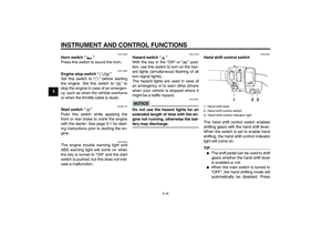 30
30 31
31 32
32 33
33 34
34 35
35 36
36 37
37 38
38 39
39 40
40 41
41 42
42 43
43 44
44 45
45 46
46 47
47 48
48 49
49 50
50 51
51 52
52 53
53 54
54 55
55 56
56 57
57 58
58 59
59 60
60 61
61 62
62 63
63 64
64 65
65 66
66 67
67 68
68 69
69 70
70 71
71 72
72 73
73 74
74 75
75 76
76 77
77 78
78 79
79 80
80 81
81 82
82 83
83 84
84 85
85 86
86 87
87 88
88 89
89 90
90 91
91 92
92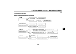 93
93 94
94 95
95 96
96 97
97 98
98 99
99 100
100 101
101 102
102 103
103 104
104 105
105 106
106 107
107