2009 SUBARU TRIBECA Repair manual
[x] Cancel search: Repair manualPage 1517 of 2453
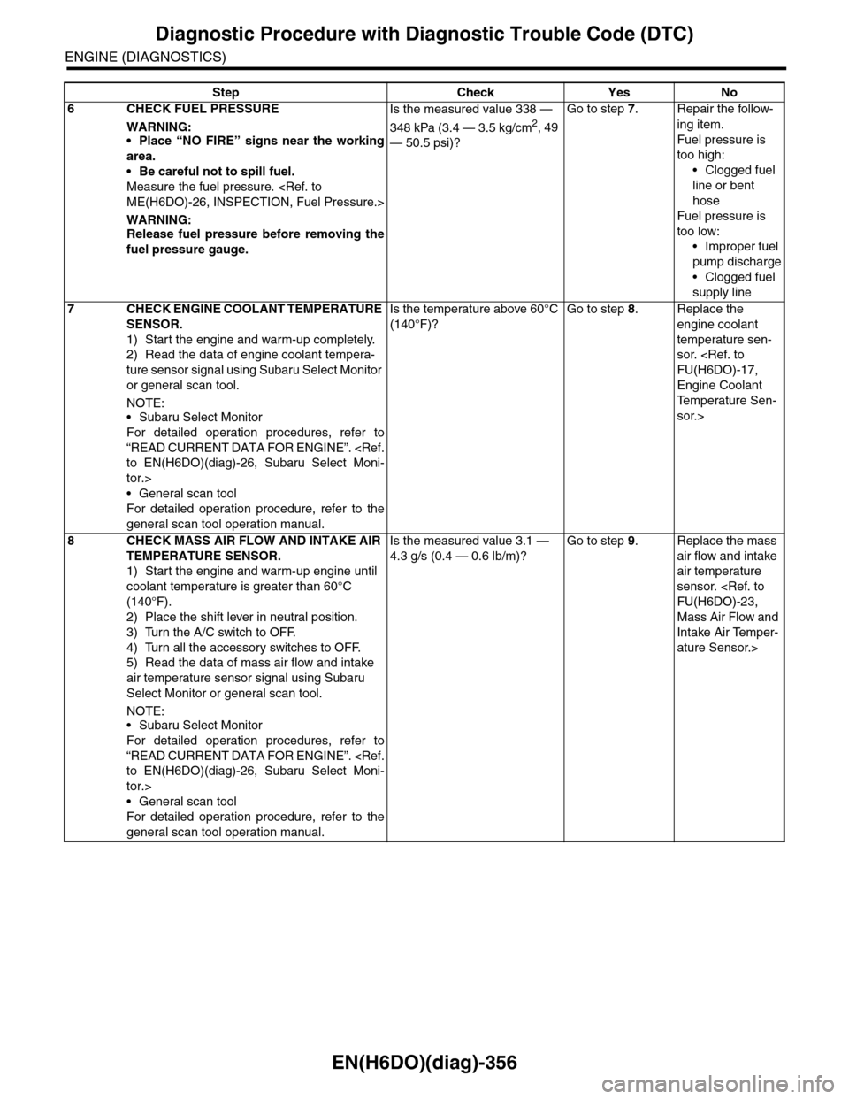
EN(H6DO)(diag)-356
Diagnostic Procedure with Diagnostic Trouble Code (DTC)
ENGINE (DIAGNOSTICS)
6CHECK FUEL PRESSURE
WARNING:•Place “NO FIRE” signs near the working
area.
•Be careful not to spill fuel.
Measure the fuel pressure.
WARNING:Release fuel pressure before removing the
fuel pressure gauge.
Is the measured value 338 —
348 kPa (3.4 — 3.5 kg/cm2, 49
— 50.5 psi)?
Go to step 7.Repair the follow-
ing item.
Fuel pressure is
too high:
•Clogged fuel
line or bent
hose
Fuel pressure is
too low:
•Improper fuel
pump discharge
•Clogged fuel
supply line
7CHECK ENGINE COOLANT TEMPERATURE
SENSOR.
1) Start the engine and warm-up completely.
2) Read the data of engine coolant tempera-
ture sensor signal using Subaru Select Monitor
or general scan tool.
NOTE:•Subaru Select Monitor
For detailed operation procedures, refer to
“READ CURRENT DATA FOR ENGINE”.
tor.>
•General scan tool
For detailed operation procedure, refer to the
general scan tool operation manual.
Is the temperature above 60°C
(140°F)?
Go to step 8.Replace the
engine coolant
temperature sen-
sor.
Engine Coolant
Te m p e r a t u r e S e n -
sor.>
8CHECK MASS AIR FLOW AND INTAKE AIR
TEMPERATURE SENSOR.
1) Start the engine and warm-up engine until
coolant temperature is greater than 60°C
(140°F).
2) Place the shift lever in neutral position.
3) Turn the A/C switch to OFF.
4) Turn all the accessory switches to OFF.
5) Read the data of mass air flow and intake
air temperature sensor signal using Subaru
Select Monitor or general scan tool.
NOTE:•Subaru Select Monitor
For detailed operation procedures, refer to
“READ CURRENT DATA FOR ENGINE”.
tor.>
•General scan tool
For detailed operation procedure, refer to the
general scan tool operation manual.
Is the measured value 3.1 —
4.3 g/s (0.4 — 0.6 lb/m)?
Go to step 9.Replace the mass
air flow and intake
air temperature
sensor.
Mass Air Flow and
Intake Air Temper-
ature Sensor.>
Step Check Yes No
Page 1518 of 2453
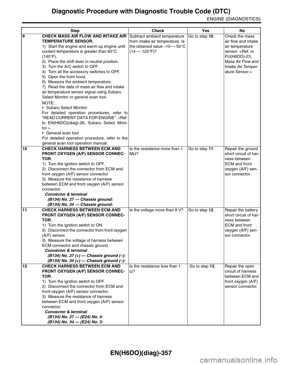
EN(H6DO)(diag)-357
Diagnostic Procedure with Diagnostic Trouble Code (DTC)
ENGINE (DIAGNOSTICS)
9CHECK MASS AIR FLOW AND INTAKE AIR
TEMPERATURE SENSOR.
1) Start the engine and warm-up engine until
coolant temperature is greater than 60°C
(140°F).
2) Place the shift lever in neutral position.
3) Turn the A/C switch to OFF.
4) Turn all the accessory switches to OFF.
5) Open the front hood.
6) Measure the ambient temperature.
7) Read the data of mass air flow and intake
air temperature sensor signal using Subaru
Select Monitor or general scan tool.
NOTE:•Subaru Select Monitor
For detailed operation procedures, refer to
“READ CURRENT DATA FOR ENGINE”.
tor.>
•General scan tool
For detailed operation procedure, refer to the
general scan tool operation manual.
Subtract ambient temperature
from intake air temperature. Is
the obtained value –10 — 50°C
(14 — 122°F)?
Go to step 10.Check the mass
air flow and intake
air temperature
sensor.
Mass Air Flow and
Intake Air Temper-
ature Sensor.>
10 CHECK HARNESS BETWEEN ECM AND
FRONT OXYGEN (A/F) SENSOR CONNEC-
TOR.
1) Turn the ignition switch to OFF.
2) Disconnect the connector from ECM and
front oxygen (A/F) sensor connector.
3) Measure the resistance of harness
between ECM and front oxygen (A/F) sensor
connector.
Connector & terminal
(B134) No. 27 — Chassis ground:
(B134) No. 34 — Chassis ground:
Is the resistance more than 1
MΩ?
Go to step 11.Repair the ground
short circuit of har-
ness between
ECM and front
oxygen (A/F) sen-
sor connector.
11 CHECK HARNESS BETWEEN ECM AND
FRONT OXYGEN (A/F) SENSOR CONNEC-
TOR.
1) Turn the ignition switch to ON.
2) Disconnect the connector from front oxygen
(A/F) sensor.
3) Measure the voltage of harness between
ECM connector and chassis ground.
Connector & terminal
(B134) No. 27 (+) — Chassis ground (–):
(B134) No. 34 (+) — Chassis ground (–):
Is the voltage more than 8 V? Go to step 12.Repair the battery
short circuit of har-
ness between
ECM and front
oxygen (A/F) sen-
sor connector.
12 CHECK HARNESS BETWEEN ECM AND
FRONT OXYGEN (A/F) SENSOR CONNEC-
TOR.
1) Turn the ignition switch to OFF.
2) Disconnect the connector from ECM and
front oxygen (A/F) sensor connector.
3) Measure the resistance of harness
between ECM and front oxygen (A/F) sensor
connector.
Connector & terminal
(B134) No. 27 — (E24) No. 4:
(B134) No. 34 — (E24) No. 3:
Is the resistance less than 1
Ω?
Go to step 13.Repair the open
circuit of harness
between ECM and
front oxygen (A/F)
sensor connector.
Step Check Yes No
Page 1519 of 2453
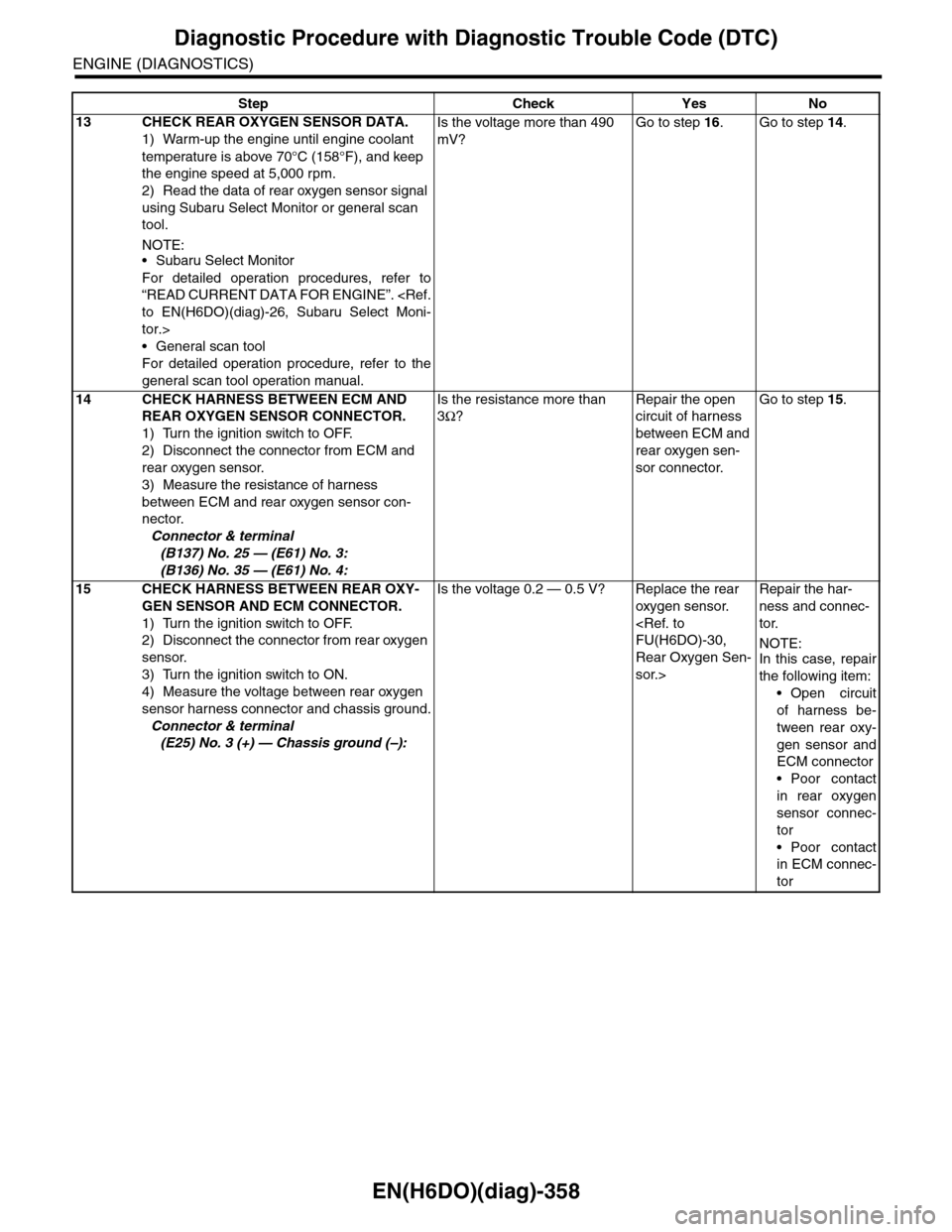
EN(H6DO)(diag)-358
Diagnostic Procedure with Diagnostic Trouble Code (DTC)
ENGINE (DIAGNOSTICS)
13 CHECK REAR OXYGEN SENSOR DATA.
1) Warm-up the engine until engine coolant
temperature is above 70°C (158°F), and keep
the engine speed at 5,000 rpm.
2) Read the data of rear oxygen sensor signal
using Subaru Select Monitor or general scan
tool.
NOTE:•Subaru Select Monitor
For detailed operation procedures, refer to
“READ CURRENT DATA FOR ENGINE”.
tor.>
•General scan tool
For detailed operation procedure, refer to the
general scan tool operation manual.
Is the voltage more than 490
mV?
Go to step 16.Go to step 14.
14 CHECK HARNESS BETWEEN ECM AND
REAR OXYGEN SENSOR CONNECTOR.
1) Turn the ignition switch to OFF.
2) Disconnect the connector from ECM and
rear oxygen sensor.
3) Measure the resistance of harness
between ECM and rear oxygen sensor con-
nector.
Connector & terminal
(B137) No. 25 — (E61) No. 3:
(B136) No. 35 — (E61) No. 4:
Is the resistance more than
3Ω?
Repair the open
circuit of harness
between ECM and
rear oxygen sen-
sor connector.
Go to step 15.
15 CHECK HARNESS BETWEEN REAR OXY-
GEN SENSOR AND ECM CONNECTOR.
1) Turn the ignition switch to OFF.
2) Disconnect the connector from rear oxygen
sensor.
3) Turn the ignition switch to ON.
4) Measure the voltage between rear oxygen
sensor harness connector and chassis ground.
Connector & terminal
(E25) No. 3 (+) — Chassis ground (–):
Is the voltage 0.2 — 0.5 V? Replace the rear
oxygen sensor.
Rear Oxygen Sen-
sor.>
Repair the har-
ness and connec-
tor.
NOTE:In this case, repair
the following item:
•Open circuit
of harness be-
tween rear oxy-
gen sensor and
ECM connector
•Poor contact
in rear oxygen
sensor connec-
tor
•Poor contact
in ECM connec-
tor
Step Check Yes No
Page 1520 of 2453
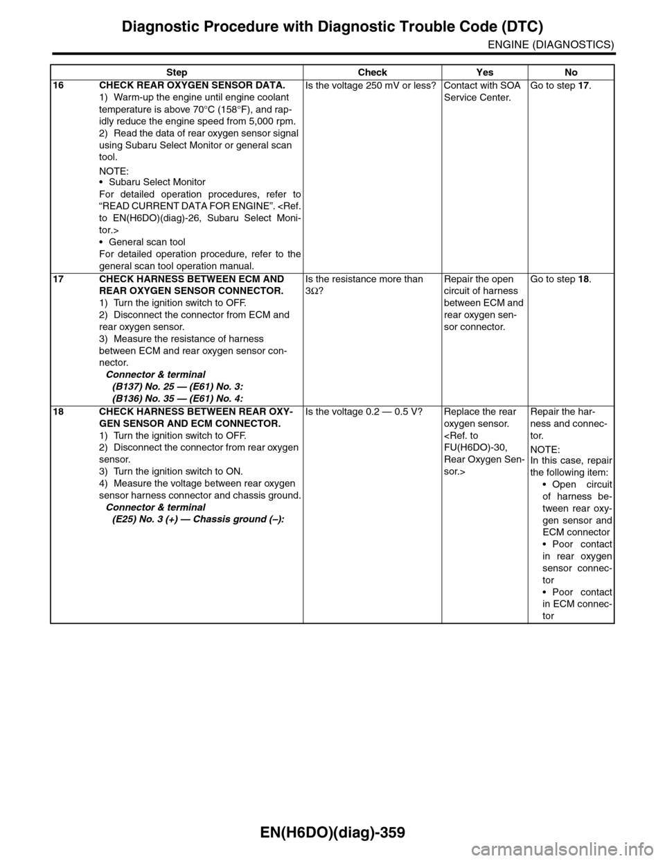
EN(H6DO)(diag)-359
Diagnostic Procedure with Diagnostic Trouble Code (DTC)
ENGINE (DIAGNOSTICS)
16 CHECK REAR OXYGEN SENSOR DATA.
1) Warm-up the engine until engine coolant
temperature is above 70°C (158°F), and rap-
idly reduce the engine speed from 5,000 rpm.
2) Read the data of rear oxygen sensor signal
using Subaru Select Monitor or general scan
tool.
NOTE:•Subaru Select Monitor
For detailed operation procedures, refer to
“READ CURRENT DATA FOR ENGINE”.
tor.>
•General scan tool
For detailed operation procedure, refer to the
general scan tool operation manual.
Is the voltage 250 mV or less? Contact with SOA
Service Center.
Go to step 17.
17 CHECK HARNESS BETWEEN ECM AND
REAR OXYGEN SENSOR CONNECTOR.
1) Turn the ignition switch to OFF.
2) Disconnect the connector from ECM and
rear oxygen sensor.
3) Measure the resistance of harness
between ECM and rear oxygen sensor con-
nector.
Connector & terminal
(B137) No. 25 — (E61) No. 3:
(B136) No. 35 — (E61) No. 4:
Is the resistance more than
3Ω?
Repair the open
circuit of harness
between ECM and
rear oxygen sen-
sor connector.
Go to step 18.
18 CHECK HARNESS BETWEEN REAR OXY-
GEN SENSOR AND ECM CONNECTOR.
1) Turn the ignition switch to OFF.
2) Disconnect the connector from rear oxygen
sensor.
3) Turn the ignition switch to ON.
4) Measure the voltage between rear oxygen
sensor harness connector and chassis ground.
Connector & terminal
(E25) No. 3 (+) — Chassis ground (–):
Is the voltage 0.2 — 0.5 V? Replace the rear
oxygen sensor.
Rear Oxygen Sen-
sor.>
Repair the har-
ness and connec-
tor.
NOTE:In this case, repair
the following item:
•Open circuit
of harness be-
tween rear oxy-
gen sensor and
ECM connector
•Poor contact
in rear oxygen
sensor connec-
tor
•Poor contact
in ECM connec-
tor
Step Check Yes No
Page 2121 of 2453
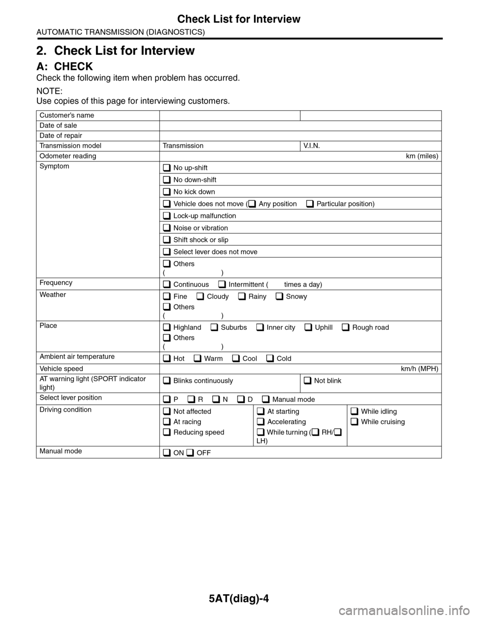
5AT(diag)-4
Check List for Interview
AUTOMATIC TRANSMISSION (DIAGNOSTICS)
2. Check List for Interview
A: CHECK
Check the following item when problem has occurred.
NOTE:
Use copies of this page for interviewing customers.
Customer’s name
Date of sale
Date of repair
Tr a n s m i s s i o n m o d e l Tr a n s m i s s i o n V. I . N .
Odometer readingkm (miles)
Symptom No up-shift
No down-shift
No kick down
Vehicle does not move ( Any position Particular position)
Lock-up malfunction
Noise or vibration
Shift shock or slip
Select lever does not move
Others
()
Fr e qu e nc y Continuous Intermittent ( times a day)
Weather Fine Cloudy Rainy Snowy
Others
()
Place Highland Suburbs Inner city Uphill Rough road
Others
()
Ambient air temperature Hot Warm Cool Cold
Ve h i c l e s p e e dkm/h (MPH)
AT w a r n i n g l i g h t ( S P O R T i n d i c a t o r
light) Blinks continuously Not blink
Select lever position P R N D Manual mode
Driving condition Not affected
At racing
Reducing speed
At starting
Accelerating
W h i l e t u r n i n g ( R H /
LH)
While idling
While cruising
Manual mode ON OFF
Page 2160 of 2453
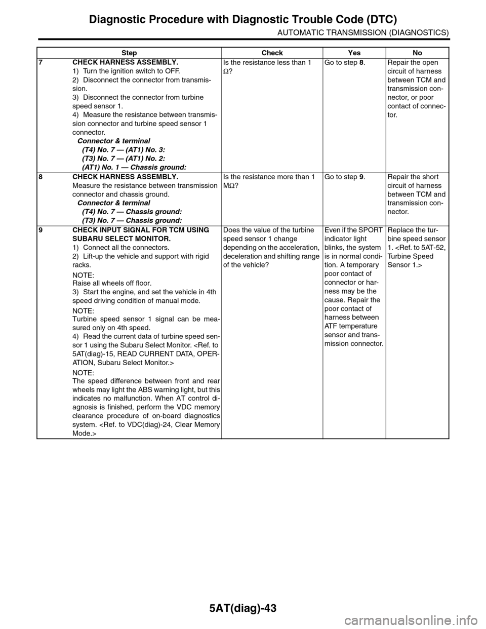
5AT(diag)-43
Diagnostic Procedure with Diagnostic Trouble Code (DTC)
AUTOMATIC TRANSMISSION (DIAGNOSTICS)
7CHECK HARNESS ASSEMBLY.
1) Turn the ignition switch to OFF.
2) Disconnect the connector from transmis-
sion.
3) Disconnect the connector from turbine
speed sensor 1.
4) Measure the resistance between transmis-
sion connector and turbine speed sensor 1
connector.
Connector & terminal
(T4) No. 7 — (AT1) No. 3:
(T3) No. 7 — (AT1) No. 2:
(AT1) No. 1 — Chassis ground:
Is the resistance less than 1
Ω?
Go to step 8.Repair the open
circuit of harness
between TCM and
transmission con-
nector, or poor
contact of connec-
tor.
8CHECK HARNESS ASSEMBLY.
Measure the resistance between transmission
connector and chassis ground.
Connector & terminal
(T4) No. 7 — Chassis ground:
(T3) No. 7 — Chassis ground:
Is the resistance more than 1
MΩ?
Go to step 9.Repair the short
circuit of harness
between TCM and
transmission con-
nector.
9CHECK INPUT SIGNAL FOR TCM USING
SUBARU SELECT MONITOR.
1) Connect all the connectors.
2) Lift-up the vehicle and support with rigid
racks.
NOTE:Raise all wheels off floor.
3) Start the engine, and set the vehicle in 4th
speed driving condition of manual mode.
NOTE:Turbine speed sensor 1 signal can be mea-
sured only on 4th speed.
4) Read the current data of turbine speed sen-
sor 1 using the Subaru Select Monitor.
AT I O N , S u b a r u S e l e c t M o n i t o r . >
NOTE:The speed difference between front and rear
wheels may light the ABS warning light, but this
indicates no malfunction. When AT control di-
agnosis is finished, perform the VDC memory
clearance procedure of on-board diagnostics
system.
Does the value of the turbine
speed sensor 1 change
depending on the acceleration,
deceleration and shifting range
of the vehicle?
Even if the SPORT
indicator light
blinks, the system
is in normal condi-
tion. A temporary
poor contact of
connector or har-
ness may be the
cause. Repair the
poor contact of
harness between
AT F t e m p e r a t u r e
sensor and trans-
mission connector.
Replace the tur-
bine speed sensor
1.
Sensor 1.>
Step Check Yes No
Page 2195 of 2453
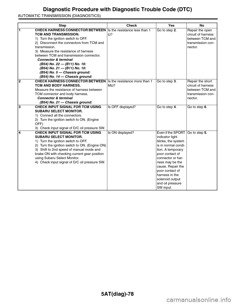
5AT(diag)-78
Diagnostic Procedure with Diagnostic Trouble Code (DTC)
AUTOMATIC TRANSMISSION (DIAGNOSTICS)
Step Check Yes No
1CHECK HARNESS CONNECTOR BETWEEN
TCM AND TRANSMISSION.
1) Turn the ignition switch to OFF.
2) Disconnect the connectors from TCM and
transmission.
3) Measure the resistance of harness
between TCM and transmission connector.
Connector & terminal
(B54) No. 22 — (B11) No. 16:
(B54) No. 21 — (B11) No. 10:
(B54) No. 5 — Chassis ground:
(B54) No. 14 — Chassis ground:
Is the resistance less than 1
Ω?
Go to step 2.Repair the open
circuit of harness
between TCM and
transmission con-
nector.
2CHECK HARNESS CONNECTOR BETWEEN
TCM AND BODY HARNESS.
Measure the resistance of harness between
TCM connector and body harness.
Connector & terminal
(B54) No. 21 — Chassis ground:
Is the resistance more than 1
MΩ?
Go to step 3.Repair the short
circuit of harness
between TCM and
transmission con-
nector.
3CHECK INPUT SIGNAL FOR TCM USING
SUBARU SELECT MONITOR.
1) Connect all the connectors.
2) Turn the ignition switch to ON. (Engine
OFF)
3) Check input signal of D/C oil pressure SW.
Is OFF displayed? Go to step 4.Go to step 6.
4CHECK INPUT SIGNAL FOR TCM USING
SUBARU SELECT MONITOR.
1) Turn the ignition switch to OFF.
2) Turn the ignition switch to ON. (Engine ON)
3) Shift to 2nd speed of manual mode and
brake ON with checking current gear position
using Subaru Select Monitor.
4) Check input signal of D/C oil pressure SW.
Is ON displayed? Even if the SPORT
indicator light
blinks, the system
is in normal condi-
tion. A temporary
poor contact of
connector or har-
ness may be the
cause. Repair the
poor contact of
harness in the
solenoid output
and oil pressure
SW input.
Go to step 5.
Page 2200 of 2453
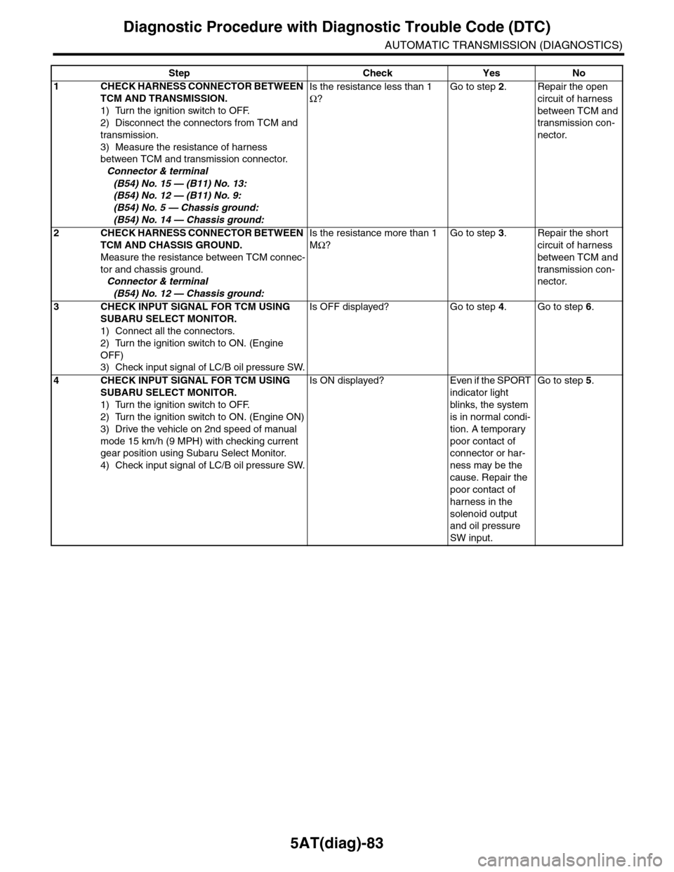
5AT(diag)-83
Diagnostic Procedure with Diagnostic Trouble Code (DTC)
AUTOMATIC TRANSMISSION (DIAGNOSTICS)
Step Check Yes No
1CHECK HARNESS CONNECTOR BETWEEN
TCM AND TRANSMISSION.
1) Turn the ignition switch to OFF.
2) Disconnect the connectors from TCM and
transmission.
3) Measure the resistance of harness
between TCM and transmission connector.
Connector & terminal
(B54) No. 15 — (B11) No. 13:
(B54) No. 12 — (B11) No. 9:
(B54) No. 5 — Chassis ground:
(B54) No. 14 — Chassis ground:
Is the resistance less than 1
Ω?
Go to step 2.Repair the open
circuit of harness
between TCM and
transmission con-
nector.
2CHECK HARNESS CONNECTOR BETWEEN
TCM AND CHASSIS GROUND.
Measure the resistance between TCM connec-
tor and chassis ground.
Connector & terminal
(B54) No. 12 — Chassis ground:
Is the resistance more than 1
MΩ?
Go to step 3.Repair the short
circuit of harness
between TCM and
transmission con-
nector.
3CHECK INPUT SIGNAL FOR TCM USING
SUBARU SELECT MONITOR.
1) Connect all the connectors.
2) Turn the ignition switch to ON. (Engine
OFF)
3) Check input signal of LC/B oil pressure SW.
Is OFF displayed? Go to step 4.Go to step 6.
4CHECK INPUT SIGNAL FOR TCM USING
SUBARU SELECT MONITOR.
1) Turn the ignition switch to OFF.
2) Turn the ignition switch to ON. (Engine ON)
3) Drive the vehicle on 2nd speed of manual
mode 15 km/h (9 MPH) with checking current
gear position using Subaru Select Monitor.
4) Check input signal of LC/B oil pressure SW.
Is ON displayed? Even if the SPORT
indicator light
blinks, the system
is in normal condi-
tion. A temporary
poor contact of
connector or har-
ness may be the
cause. Repair the
poor contact of
harness in the
solenoid output
and oil pressure
SW input.
Go to step 5.