2009 SUBARU TRIBECA immobilizer
[x] Cancel search: immobilizerPage 1197 of 2453
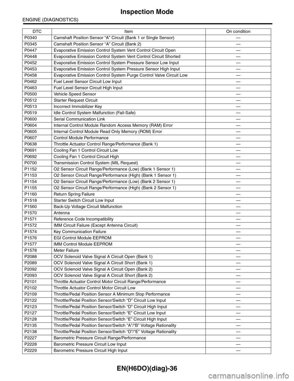
EN(H6DO)(diag)-36
Inspection Mode
ENGINE (DIAGNOSTICS)
P0340 Camshaft Position Sensor “A” Circuit (Bank 1 or Single Sensor) —
P0345 Camshaft Position Sensor “A” Circuit (Bank 2) —
P0447 Evaporative Emission Control System Vent Control Circuit Open —
P0448 Evaporative Emission Control System Vent Control Circuit Shorted —
P0452 Evaporative Emission Control System Pressure Sensor Low Input —
P0453 Evaporative Emission Control System Pressure Sensor High Input —
P0458 Evaporative Emission Control System Purge Control Valve Circuit Low —
P0462 Fuel Level Sensor Circuit Low Input —
P0463 Fuel Level Sensor Circuit High Input —
P0500 Vehicle Speed Sensor—
P0512 Starter Request Circuit—
P0513 Incorrect Immobilizer Key —
P0519 Idle Control System Malfunction (Fail-Safe) —
P0600 Serial Communication Link —
P0604 Internal Control Module Random Access Memory (RAM) Error —
P0605 Internal Control Module Read Only Memory (ROM) Error —
P0607 Control Module Performance —
P0638 Throttle Actuator Control Range/Performance (Bank 1) —
P0691 Cooling Fan 1 Control Circuit Low —
P0692 Cooling Fan 1 Control Circuit High —
P0700 Transmission Control System (MIL Request) —
P1152 O2 Sensor Circuit Range/Performance (Low) (Bank 1 Sensor 1) —
P1153 O2 Sensor Circuit Range/Performance (High) (Bank 1 Sensor 1) —
P1154 O2 Sensor Circuit Range/Performance (Low) (Bank 2 Sensor 1) —
P1155 O2 Sensor Circuit Range/Performance (High) (Bank 2 Sensor 1) —
P1160 Return Spring Failure—
P1518 Starter Switch Circuit Low Input —
P1560 Back-Up Voltage Circuit Malfunction —
P1570 Antenna—
P1571 Reference Code Incompatibility —
P1572 IMM Circuit Failure (Except Antenna Circuit) —
P1574 Key Communication Failure —
P1576 EGI Control Module EEPROM —
P1577 IMM Control Module EEPROM —
P1578 Meter Failure—
P2088 OCV Solenoid Valve Signal A Circuit Open (Bank 1) —
P2089 OCV Solenoid Valve Signal A Circuit Short (Bank 1) —
P2092 OCV Solenoid Valve Signal A Circuit Open (Bank 2) —
P2093 OCV Solenoid Valve Signal A Circuit Short (Bank 2) —
P2101 Throttle Actuator Control Motor Circuit Range/Performance —
P2102 Throttle Actuator Control Motor Circuit Low —
P2109 Throttle/Pedal Position Sensor A Minimum Stop Performance —
P2122 Throttle/Pedal Position Sensor/Switch “D” Circuit Low Input —
P2123 Throttle/Pedal Position Sensor/Switch “D” Circuit High Input —
P2127 Throttle/Pedal Position Sensor/Switch “E” Circuit Low Input —
P2128 Throttle/Pedal Position Sensor/Switch “E” Circuit High Input —
P2135 Throttle/Pedal Position Sensor/Switch “A”/“B” Voltage Rationality —
P2138 Throttle/Pedal Position Sensor/Switch “D”/“E” Voltage Rationality —
P2227 Barometric Pressure Circuit Range/Performance —
P2228 Barometric Pressure Circuit Low Input —
P2229 Barometric Pressure Circuit High Input —
DTC Item On condition
Page 1593 of 2453
FU(H6DO)-32
Engine Control Module (ECM)
FUEL INJECTION (FUEL SYSTEMS)
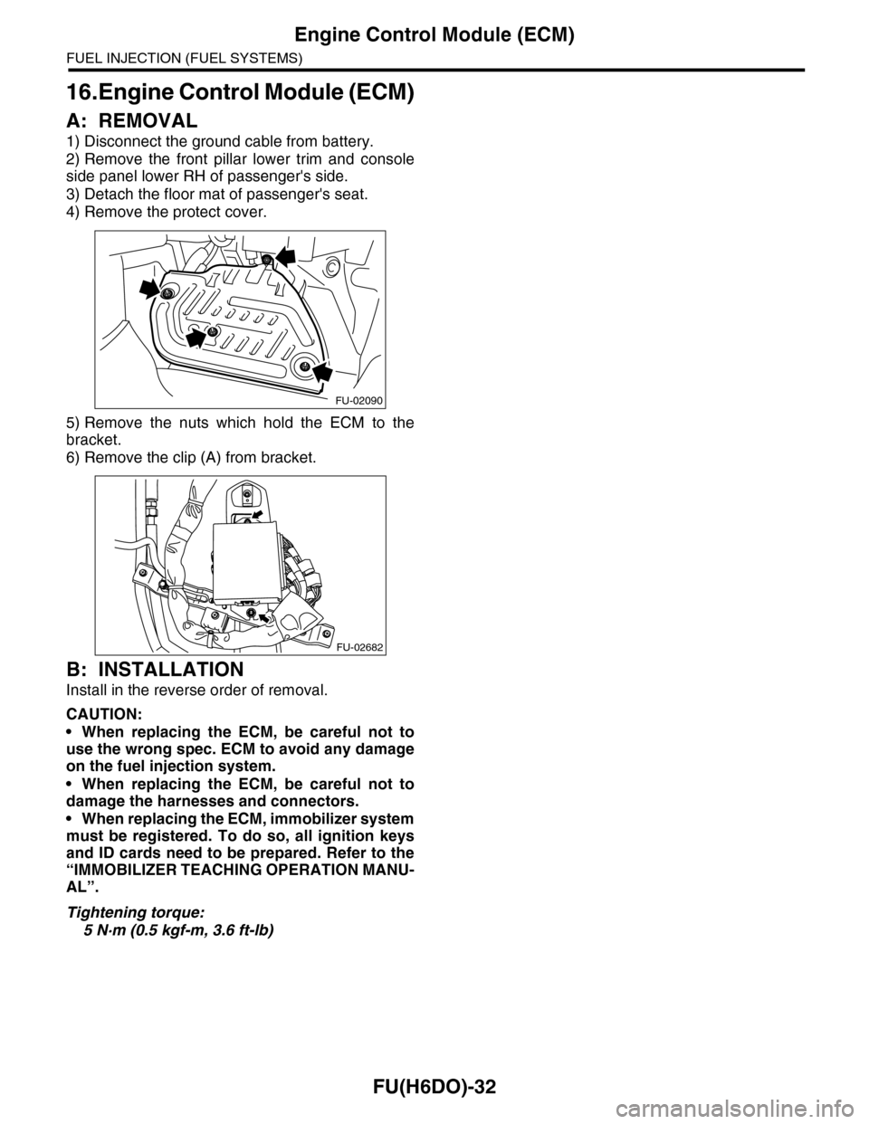
16.Engine Control Module (ECM)
A: REMOVAL
1) Disconnect the ground cable from battery.
2) Remove the front pillar lower trim and console
side panel lower RH of passenger's side.
3) Detach the floor mat of passenger's seat.
4) Remove the protect cover.
5) Remove the nuts which hold the ECM to the
bracket.
6) Remove the clip (A) from bracket.
B: INSTALLATION
Install in the reverse order of removal.
CAUTION:
•When replacing the ECM, be careful not to
use the wrong spec. ECM to avoid any damage
on the fuel injection system.
•When replacing the ECM, be careful not to
damage the harnesses and connectors.
•When replacing the ECM, immobilizer system
must be registered. To do so, all ignition keys
and ID cards need to be prepared. Refer to the
“IMMOBILIZER TEACHING OPERATION MANU-
AL”.
Tightening torque:
5 N·m (0.5 kgf-m, 3.6 ft-lb)
FU-02090
FU-02682
Page 1618 of 2453
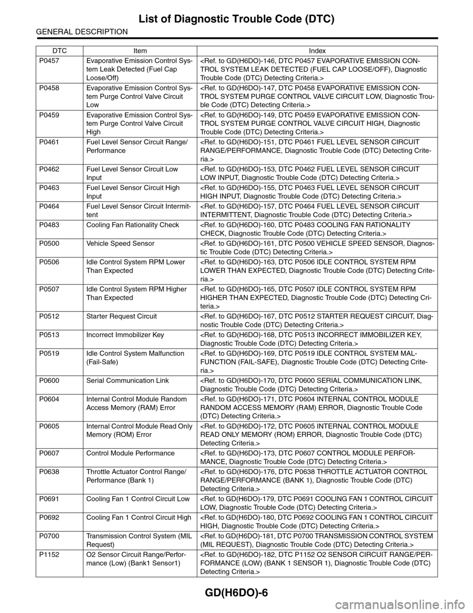
GD(H6DO)-6
List of Diagnostic Trouble Code (DTC)
GENERAL DESCRIPTION
P0457 Evaporative Emission Control Sys-
tem Leak Detected (Fuel Cap
Loose/Off)
Tr o u b l e C o d e ( D T C ) D e t e c t i n g C r i t e r i a . >
P0458 Evaporative Emission Control Sys-
tem Purge Control Valve Circuit
Low
ble Code (DTC) Detecting Criteria.>
P0459 Evaporative Emission Control Sys-
tem Purge Control Valve Circuit
High
Tr o u b l e C o d e ( D T C ) D e t e c t i n g C r i t e r i a . >
P0461 Fuel Level Sensor Circuit Range/
Per fo r m an ce
ria.>
P0462 Fuel Level Sensor Circuit Low
Input
P0463 Fuel Level Sensor Circuit High
Input
P0464 Fuel Level Sensor Circuit Intermit-
tent
P0483 Cooling Fan Rationality Check
P0500 Vehicle Speed Sensor
P0506 Idle Control System RPM Lower
Than Expected
ria.>
P0507 Idle Control System RPM Higher
Than Expected
teria.>
P0512 Starter Request Circuit
P0513 Incorrect Immobilizer Key
P0519 Idle Control System Malfunction
(Fail-Safe)
ria.>
P0600 Serial Communication Link
P0604 Internal Control Module Random
Access Memory (RAM) Error
(DTC) Detecting Criteria.>
P0605 Internal Control Module Read Only
Memory (ROM) Error
Detecting Criteria.>
P0607 Control Module Performance
P0638 Throttle Actuator Control Range/
Per fo r m an ce ( B an k 1 )
Detecting Criteria.>
P0691 Cooling Fan 1 Control Circuit Low
P0692 Cooling Fan 1 Control Circuit High
P0700 Transmission Control System (MIL
Request)
P1152 O2 Sensor Circuit Range/Perfor-
mance (Low) (Bank1 Sensor1)
Detecting Criteria.>
DTC Item Index
Page 1780 of 2453
GD(H6DO)-168
Diagnostic Trouble Code (DTC) Detecting Criteria
GENERAL DESCRIPTION
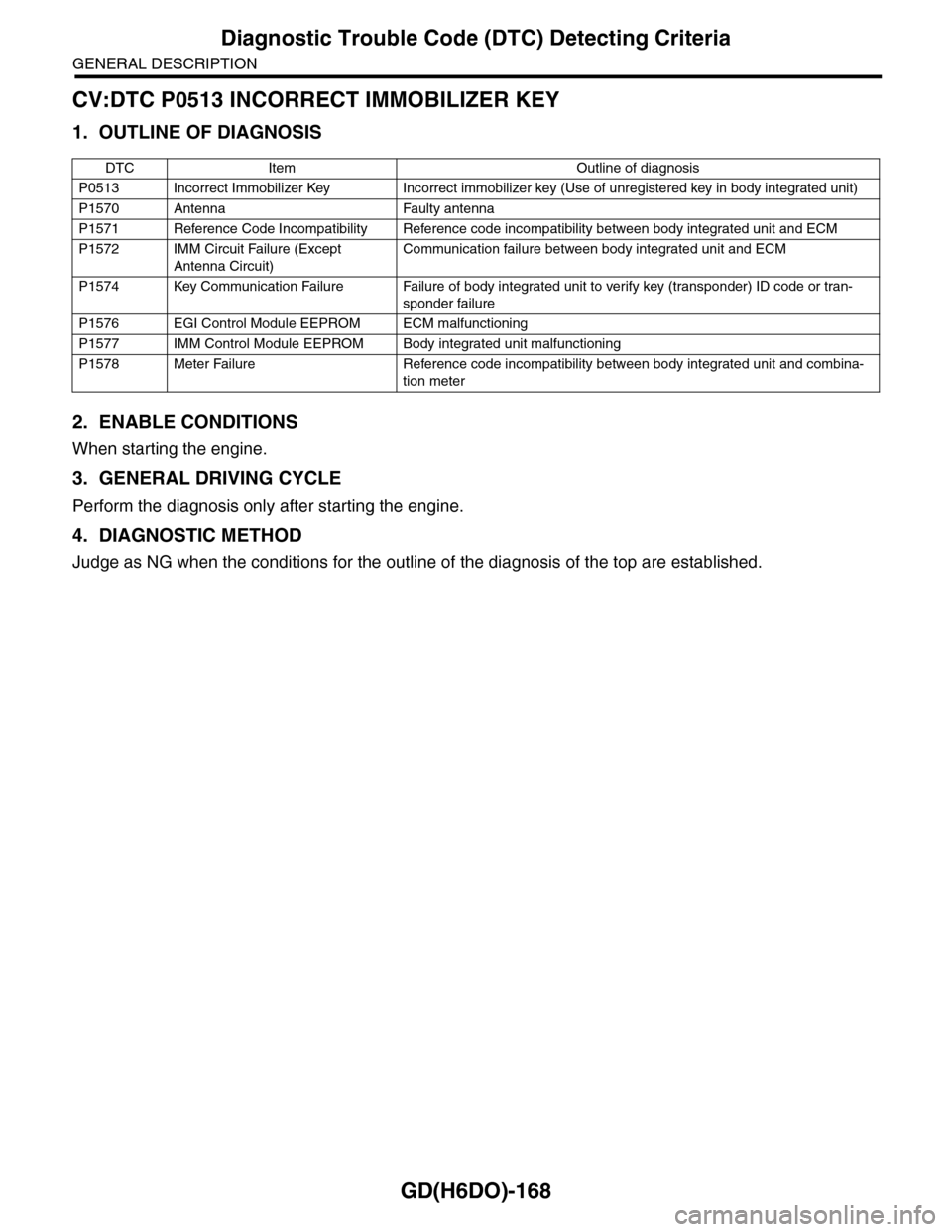
CV:DTC P0513 INCORRECT IMMOBILIZER KEY
1. OUTLINE OF DIAGNOSIS
2. ENABLE CONDITIONS
When starting the engine.
3. GENERAL DRIVING CYCLE
Perform the diagnosis only after starting the engine.
4. DIAGNOSTIC METHOD
Judge as NG when the conditions for the outline of the diagnosis of the top are established.
DTC Item Outline of diagnosis
P0513 Incorrect Immobilizer Key Incorrect immobilizer key (Use of unregistered key in body integrated unit)
P1570 Antenna Faulty antenna
P1571 Reference Code Incompatibility Reference code incompatibility between body integrated unit and ECM
P1572 IMM Circuit Failure (Except
Antenna Circuit)
Communication failure between body integrated unit and ECM
P1574 Key Communication Failure Failure of body integrated unit to verify key (transponder) ID code or tran-
sponder failure
P1576 EGI Control Module EEPROM ECM malfunctioning
P1577 IMM Control Module EEPROM Body integrated unit malfunctioning
P1578 Meter Failure Reference code incompatibility between body integrated unit and combina-
tion meter
Page 1805 of 2453
GD(H6DO)-193
Diagnostic Trouble Code (DTC) Detecting Criteria
GENERAL DESCRIPTION
DN:DTC P1570 ANTENNA
1. OUTLINE OF DIAGNOSIS
For the detection standard, refer to DTC P0513 NO INCORRECT IMMOBILIZER KEY.
DO:DTC P1571 REFERENCE CODE INCOMPATIBILITY
1. OUTLINE OF DIAGNOSIS
For the detection standard, refer to DTC P0513 NO INCORRECT IMMOBILIZER KEY.
DP:DTC P1572 IMM CIRCUIT FAILURE (EXCEPT ANTENNA CIRCUIT)
1. OUTLINE OF DIAGNOSIS
For the detection standard, refer to DTC P0513 NO INCORRECT IMMOBILIZER KEY.
DQ:DTC P1574 KEY COMMUNICATION FAILURE
1. OUTLINE OF DIAGNOSIS
For the detection standard, refer to DTC P0513 NO INCORRECT IMMOBILIZER KEY.
DR:DTC P1576 EGI CONTROL MODULE EEPROM
1. OUTLINE OF DIAGNOSIS
For the detection standard, refer to DTC P0513 NO INCORRECT IMMOBILIZER KEY.
DS:DTC P1577 IMM CONTROL MODULE EEPROM
1. OUTLINE OF DIAGNOSIS
For the detection standard, refer to DTC P0513 NO INCORRECT IMMOBILIZER KEY.
DT:DTC P1578 METER FAILURE
1. OUTLINE OF DIAGNOSIS
For the detection standard, refer to DTC P0513 NO INCORRECT IMMOBILIZER KEY.
Page 2316 of 2453
WI-32
Engine Electrical System
WIRING SYSTEM
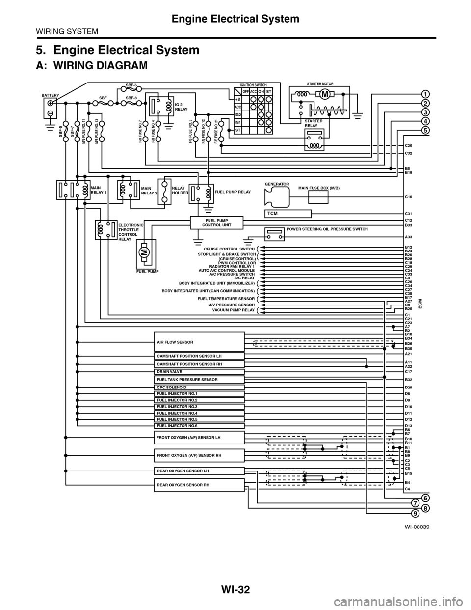
5. Engine Electrical System
A: WIRING DIAGRAM
WI-08039
678
1
2
3
4
5
C20
C32
C31
B5B19
B33
A33
C10
ECMC1B25C8A27
C21C23A7
D29
B2
BATTERY
M/B FUSE NO. 11SBF-7
SBF
SBF-5
SBF-8
SBF-6
STARTERRELAY
IG 2RELAY
IGNITION SWITCHOFF+B
ACC
IG2
IG1
ACCONST
ST
STARTER MOTOR
MAINRELAY 1
ELECTRONICTHROTTLECONTROLRELAY
FUEL PUMP RELAY
FUEL PUMP
FUEL PUMPCONTROL UNIT
MAINRELAY 2RELAYHOLDER
A21
A11A22
B34
B35
B7B6
B11B10
B9B8
C2
B26AIR FLOW SENSOR
CAMSHAFT POSITION SENSOR LH
CPC SOLENOID
B1
C3C5B15
B4C4
POWER STEERING OIL PRESSURE SWITCH
C12
MAIN FUSE BOX (M/B)GENERATOR
B18
TCM
D8FUEL INJECTOR NO.1D9D10D11
PWM CONTROLLORAUTO A/C CONTROL MODULE
A/C RELAY
BODY INTEGRATED UNIT (CAN COMMUNICATION)
FUEL TEMPERATURE SENSOR
VACUUM PUMP RELAY
BODY INTEGRATED UNIT (IMMOBILIZER)
C18C29C24C33
C27
B24B12
B20B28
C26C34
C35B17
CRUISE CONTROL SWITCH
FUEL INJECTOR NO.2FUEL INJECTOR NO.3
C17DRAIN VALVE
FUEL INJECTOR NO.4D12D13FUEL INJECTOR NO.5FUEL INJECTOR NO.6
FRONT OXYGEN (A/F) SENSOR RH
REAR OXYGEN SENSOR RH
REAR OXYGEN SENSOR LH
FRONT OXYGEN (A/F) SENSOR LH
A/C PRESSURE SWITCH
M/V PRESSURE SENSOR
RADIATOR FAN RELAY 1
STOP LIGHT & BRAKE SWITCH(CRUISE CONTROL)
C9
FUEL TANK PRESSURE SENSORB32
M/B FUSE NO. 13F/B FUSE NO. 7F/B FUSE NO. 4F/B FUSE NO. 5F/B FUSE NO. 12F/B FUSE NO. 21
CAMSHAFT POSITION SENSOR RH
9
Page 2319 of 2453
![SUBARU TRIBECA 2009 1.G Service Workshop Manual WI-35
Engine Electrical System
WIRING SYSTEM
WI-08042
E/G-02E/G-02
ECM
WL
C26
BP
C34
REF. TO AT CONTROLSYSTEM [5AT-05] REF. TO CRUISECONTROL SYSTEM [C/C-01] REF. TO STOP LIGHTSYSTEM [S/L-01]REF. TO SUBARU TRIBECA 2009 1.G Service Workshop Manual WI-35
Engine Electrical System
WIRING SYSTEM
WI-08042
E/G-02E/G-02
ECM
WL
C26
BP
C34
REF. TO AT CONTROLSYSTEM [5AT-05] REF. TO CRUISECONTROL SYSTEM [C/C-01] REF. TO STOP LIGHTSYSTEM [S/L-01]REF. TO](/manual-img/17/7322/w960_7322-2318.png)
WI-35
Engine Electrical System
WIRING SYSTEM
WI-08042
E/G-02E/G-02
ECM
WL
C26
BP
C34
REF. TO AT CONTROLSYSTEM [5AT-05] REF. TO CRUISECONTROL SYSTEM [C/C-01] REF. TO STOP LIGHTSYSTEM [S/L-01]REF. TO IMMOBILIZER SYSTEM [IMB-01] REF. TO RADIATOR FAN SYSTEM [R/F-01] REF. TO FRONT AIR CONDITIONER SYSTEM [F-A/C-01•02]
GL
C31
C:B136B:B135A:B134
WL
B12
LP
B24
BrR
B28
Y
B20
PW
C24
YB
C33
LOr
C9
REF. TO VACUUMPUMP SYSTEM [VPC-01]
Y
C8
RB
A27
WR
B25
RY
C18
GR
C29
C:B136B135B:
5672134
29
101112131415252416
30
98171819202821222332312627333435
16101112131415252430
9871718192028212223293231
123456
2726333435
A:B134
85610 11 12 13 14 157213416
3019 20 2228 29
91718252123 24323126 2733 34
Page 2358 of 2453
WI-74
Immobilizer System
WIRING SYSTEM
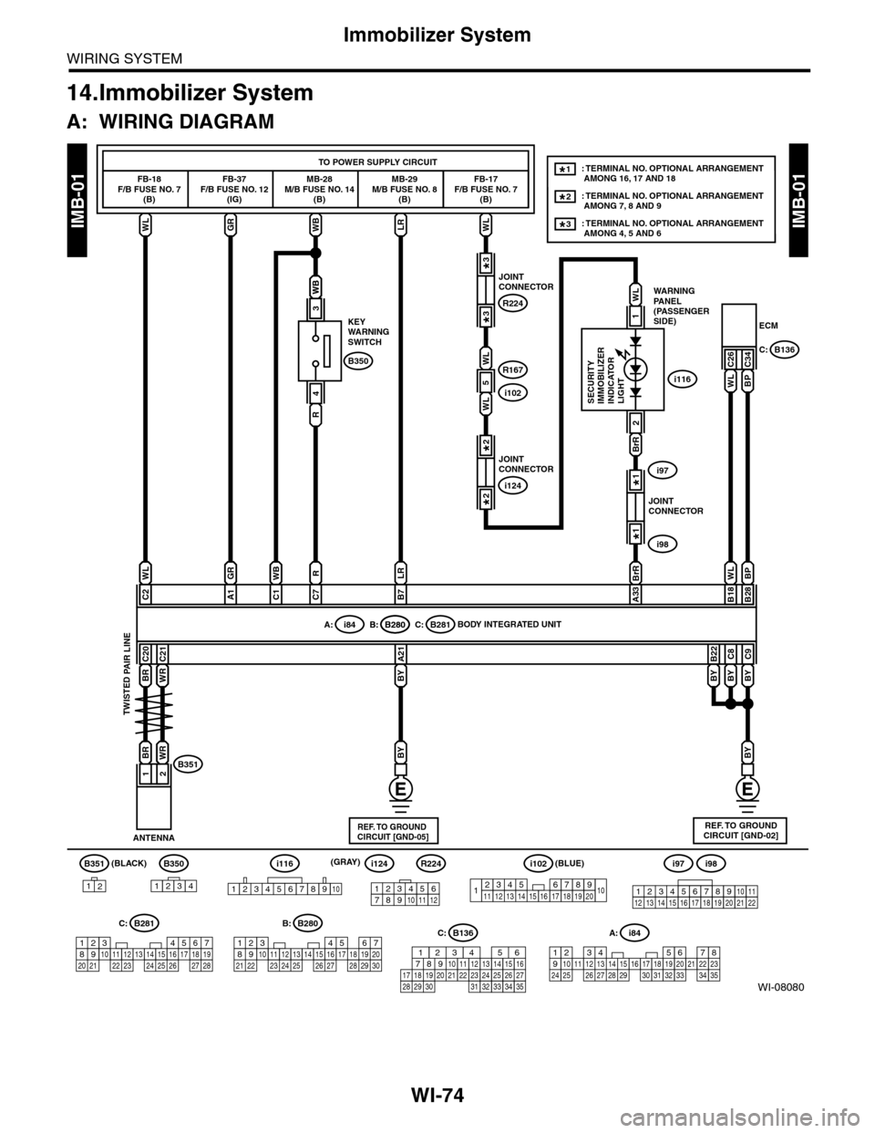
14.Immobilizer System
A: WIRING DIAGRAM
WI-08080
IMB-01IMB-01
BR
B351
12
B350
1234
A: i84
1234567891011121415161718192021222324252627282930313233343513
WLGRWBLRWL
FB-18F/B FUSE NO. 7(B)
FB-37F/B FUSE NO. 12(IG)
MB-28M/B FUSE NO. 14(B)
KEYWARNINGSWITCH
MB-29M/B FUSE NO. 8(B)
FB-17F/B FUSE NO. 7(B)
ECM
TO POWER SUPPLY CIRCUIT
C26C34B350
WB
R
4
WB
3
WL
C2
GR
A1
RWB
C7C1
LR
B7
BrR BrR
A33
BP
B28
WL
B18
BYBY
BY
C9
BY
C8
BY
B22
WLBP
A: i84B: B280C: B281B: B280
C20
WR
BRWR
C21
BY
A21
12
ANTENNA
BODY INTEGRATED UNIT
B351
WARNINGPANEL(PASSENGERSIDE)
SECURITYIMMOBILIZERINDICATORLIGHT
B136C:
2
56782194310242223 25111213141526 27 281617181920 21
B281C:
5467821931022 23111213141524 25 26 2716171828 29192021 30
B280B:
i116
REF. TO GROUNDCIRCUIT [GND-02]
(BLACK)
TWISTED PAIR LINE
JOINTCONNECTOR
i97
i98
1*
1*
JOINTCONNECTOR
R224
R167
i102
3*
3*
JOINTCONNECTOR
i124
2*
2*
1
WL
: TERMINAL NO. OPTIONAL ARRANGEMENT AMONG 16, 17 AND 18
: TERMINAL NO. OPTIONAL ARRANGEMENT AMONG 7, 8 AND 9
1*
2*
: TERMINAL NO. OPTIONAL ARRANGEMENT AMONG 4, 5 AND 63*
123456789101112
i124i98i97
12345678910111213141516171819202122
i116
12345678910
C: B136
16101112131415252430
9871718192028212223293231
123456
2726333435
R224
1234567891413121110151617181920
i102(BLUE)
5
WL
WL
REF. TO GROUNDCIRCUIT [GND-05]
(GRAY)