Page 2241 of 2453
5AT(diag)-124
Diagnostic Procedure without Diagnostic Trouble Code (DTC)
AUTOMATIC TRANSMISSION (DIAGNOSTICS)
B: CHECK RANGE POSITION/GEAR POSITION INDICATOR LIGHT
DIAGNOSIS:
Output signal circuit of the range position/gear position indicator light is open or shorted.
TROUBLE SYMPTOM:
•Range position/gear position indicator light does not illuminate or remains illuminated.
•Cannot understand range position/gear position indicator light display.
WIRING DIAGRAM:
AT-03290
34
2930
COMBINATIONMETER
i10
A27A26
B20B30
BODY INTEGRATED UNIT
i84A:
B280B:
43
TCMB54
BATTERY
MAIN SBF SBF-6 NO.5
E
IGNITIONSWITCH
i84
8765432122232120191615141312111093435333217301831292827262524
A:
B54
12789563410 11 1219 20 2113 14 15 16 17 18222324
B280
87654321
2223212019161514131211109173018292827262524
B:
i10
123456789101112131415161718192021222324252627282930
RANGE POSITION/GEAR POSITIONINDICATOR
Page 2243 of 2453
5AT(diag)-126
Diagnostic Procedure without Diagnostic Trouble Code (DTC)
AUTOMATIC TRANSMISSION (DIAGNOSTICS)
C: CHECK BUZZER
DIAGNOSIS:
Output signal circuit of buzzer is open or shorted.
TROUBLE SYMPTOM:
Buzzer remains beeping.
WIRING DIAGRAM:
34
2122
AT-02940
17
COMBINATIONMETER
JOINT CONNECTOR
i77
i10
i84A:B280B:
28
A27A26
B20B30
43
TCMB54
BODY INTEGRATED UNIT
SPORTSHIFTBUZZER
i10
i77
i84
B280
21346789102221201918171615141312115
121110987654321
8765432122232120191615141312111093435333217301831292827262524
87654321
2223212019161514131211109173018292827262524
BATTERY
SBF-1 SBF-7
IGNITION SWITCH
NO.12
EA:
B:
B54
12789563410 11 1219 20 2113 14 15 16 17 18222324
Page 2260 of 2453
CS-8
AT Shift Lock Control System
CONTROL SYSTEMS
C: WIRING DIAGRAM
(1) Ignition switch (4) Body integrated unit (7) Shift lock solenoid
(2) Stop light switch (5) TCM (“P” range) (8) “P” range switch
(3) Key warning switch (6) Key lock solenoid (9) Battery
CS-00363
OFFACCON
(1)
(2)
(3)
(4)
(9)
(6)
(7)
(8)
(5)
Page 2287 of 2453
WI-3
Basic Diagnostic Procedure
WIRING SYSTEM
1. Basic Diagnostic Procedure
A: BASIC PROCEDURES
1. GENERAL DESCRIPTION
The most important purpose of diagnostics is to
quickly determine which part is malfunctioning, to
save time and labor.
2. IDENTIFICATION OF TROUBLE SYMP-
TOM
Determine what the problem is based on the symp-
tom.
3. PROBABLE CAUSE OF TROUBLE
Look at the wiring diagram and check the system’s
circuit. Then check the switch, relay, fuse, ground,
etc.
4. LOCATION AND REPAIR OF TROUBLE
1) Using the diagnostics, narrow down the causes.
2) If necessary, use a voltmeter, ohmmeter, etc.
3) Before replacing certain component parts
(switch, relay, etc.), check the power supply,
ground, for open wiring harness, poor connectors,
etc. If no problem is encountered, check the com-
ponent parts.
5. SYSTEM OPERATION CHECK
After repairing, ensure that the system operates
properly.
B: BASIC INSPECTION
1. VOLTAGE MEASUREMENT
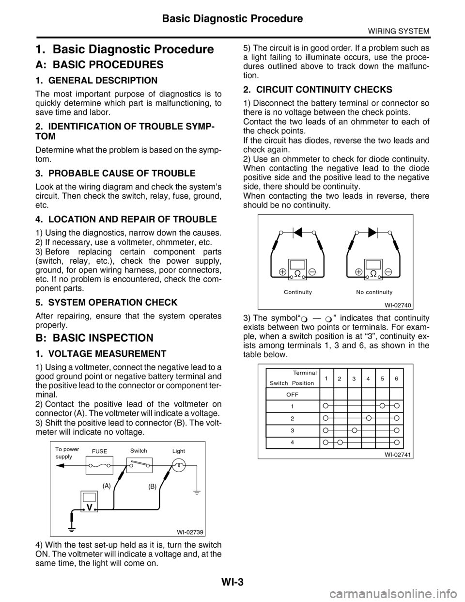
1) Using a voltmeter, connect the negative lead to a
good ground point or negative battery terminal and
the positive lead to the connector or component ter-
minal.
2) Contact the positive lead of the voltmeter on
connector (A). The voltmeter will indicate a voltage.
3) Shift the positive lead to connector (B). The volt-
meter will indicate no voltage.
4) With the test set-up held as it is, turn the switch
ON. The voltmeter will indicate a voltage and, at the
same time, the light will come on.
5) The circuit is in good order. If a problem such as
a light failing to illuminate occurs, use the proce-
dures outlined above to track down the malfunc-
tion.
2. CIRCUIT CONTINUITY CHECKS
1) Disconnect the battery terminal or connector so
there is no voltage between the check points.
Contact the two leads of an ohmmeter to each of
the check points.
If the circuit has diodes, reverse the two leads and
check again.
2) Use an ohmmeter to check for diode continuity.
When contacting the negative lead to the diode
positive side and the positive lead to the negative
side, there should be continuity.
When contacting the two leads in reverse, there
should be no continuity.
3) The symbol“ — ” indicates that continuity
exists between two points or terminals. For exam-
ple, when a switch position is at “3”, continuity ex-
ists among terminals 1, 3 and 6, as shown in the
table below.
WI-02739
To powerFUSEsupplySwitchLight
V
(A)(B)
WI-02740
Continuity No continuity
�
Page 2288 of 2453
WI-4
Basic Diagnostic Procedure
WIRING SYSTEM
3. HOW TO DETERMINE AN OPEN CIR-
CUIT
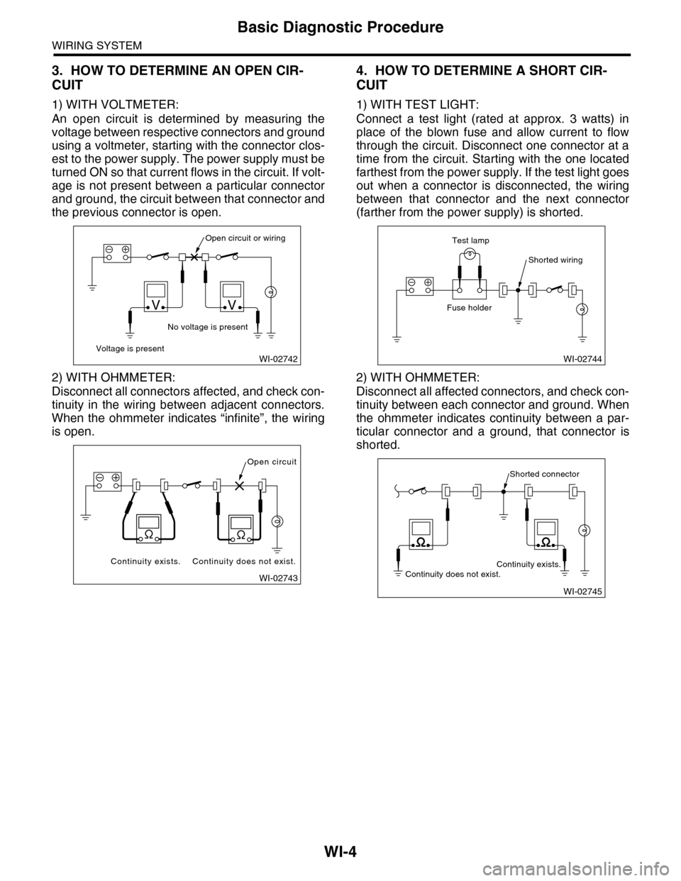
1) WITH VOLTMETER:
An open circuit is determined by measuring the
voltage between respective connectors and ground
using a voltmeter, starting with the connector clos-
est to the power supply. The power supply must be
turned ON so that current flows in the circuit. If volt-
age is not present between a particular connector
and ground, the circuit between that connector and
the previous connector is open.
2) WITH OHMMETER:
Disconnect all connectors affected, and check con-
tinuity in the wiring between adjacent connectors.
When the ohmmeter indicates “infinite”, the wiring
is open.
4. HOW TO DETERMINE A SHORT CIR-
CUIT
1) WITH TEST LIGHT:
Connect a test light (rated at approx. 3 watts) in
place of the blown fuse and allow current to flow
through the circuit. Disconnect one connector at a
time from the circuit. Starting with the one located
farthest from the power supply. If the test light goes
out when a connector is disconnected, the wiring
between that connector and the next connector
(farther from the power supply) is shorted.
2) WITH OHMMETER:
Disconnect all affected connectors, and check con-
tinuity between each connector and ground. When
the ohmmeter indicates continuity between a par-
ticular connector and a ground, that connector is
shorted.
WI-02742
Open circuit or wiring
No voltage is present
Voltage is present
VV
WI-02743
Open circuit
Continuity does not exist.Continuity exists.
WI-02744
Shorted wiring
Test lamp
Fuse holder
WI-02745
Shorted connector
Continuity does not exist.Continuity exists.
Page 2289 of 2453
WI-5
Basic Diagnostic Procedure
WIRING SYSTEM
C: HOW TO READ WIRING DIA-
GRAMS
1. WIRING DIAGRAM
The wiring diagram of each system is illustrated so
that you can understand the path through which the
electric current flows from the battery.
Sketches and codes are used in the diagrams.
They should read as follows:
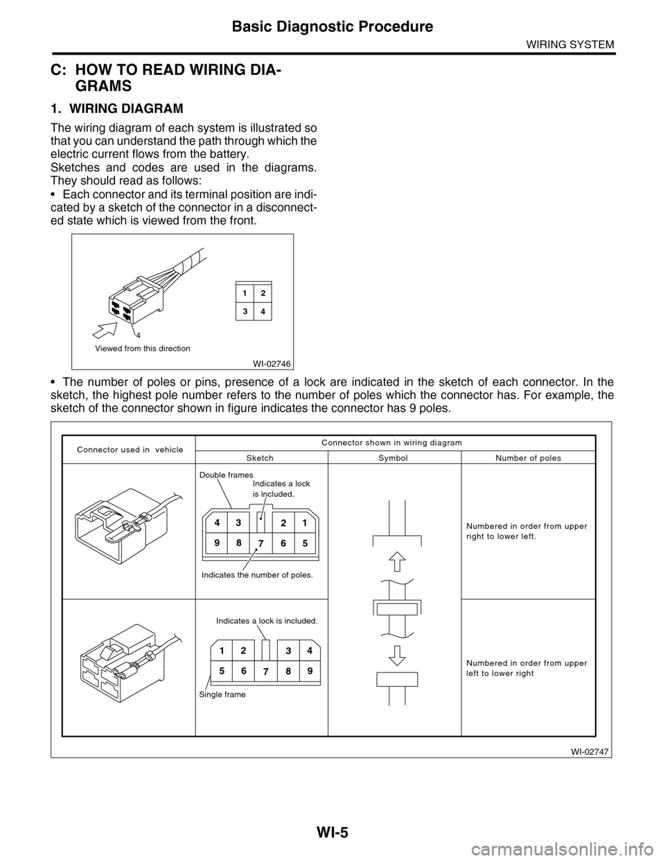
•Each connector and its terminal position are indi-
cated by a sketch of the connector in a disconnect-
ed state which is viewed from the front.
•The number of poles or pins, presence of a lock are indicated in the sketch of each connector. In the
sketch, the highest pole number refers to the number of poles which the connector has. For example, the
sketch of the connector shown in figure indicates the connector has 9 poles.
WI-02746
Viewed from this direction
4
2
4
1
3
WI-02747
Connector used in vehicleSketch Symbol Number of poles
Numbered in order from upperright to lower left.
Numbered in order from upperleft to lower right
Connector shown in wiring diagram
Double framesIndicates a lock is included.
Indicates the number of poles.
4321
98765
Indicates a lock is included.
Single frame
1234
56789
Page 2290 of 2453
WI-6
Basic Diagnostic Procedure
WIRING SYSTEM
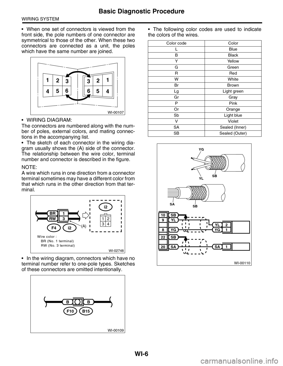
•When one set of connectors is viewed from the
front side, the pole numbers of one connector are
symmetrical to those of the other. When these two
connectors are connected as a unit, the poles
which have the same number are joined.
•WIRING DIAGRAM:
The connectors are numbered along with the num-
ber of poles, external colors, and mating connec-
tions in the accompanying list.
•The sketch of each connector in the wiring dia-
gram usually shows the (A) side of the connector.
The relationship between the wire color, terminal
number and connector is described in the figure.
NOTE:
A wire which runs in one direction from a connector
terminal sometimes may have a different color from
that which runs in the other direction from that ter-
minal.
•In the wiring diagram, connectors which have no
terminal number refer to one-pole types. Sketches
of these connectors are omitted intentionally.
•The following color codes are used to indicate
the colors of the wires.
WI-00107
112233
445566
WI-02748
Wire color :BR (No. 1 terminal)RW (No. 3 terminal)
i2
34
12
BR
RW
i2F4
1
3
(A)
WI-00109
BB
B15F10
Color code Color
LBlue
BBlack
YYellow
GGreen
RRed
WWhite
Br Brown
Lg Light green
Gr Gray
PPink
Or Orange
Sb Light blue
VViolet
SA Sealed (Inner)
SB Sealed (Outer)
WI-00110
YL 2
YG 1
SB10
YL9
YG8
SA 1
SB22
SA20
YG
YLSB
SBSA
Page 2291 of 2453
WI-7
Basic Diagnostic Procedure
WIRING SYSTEM
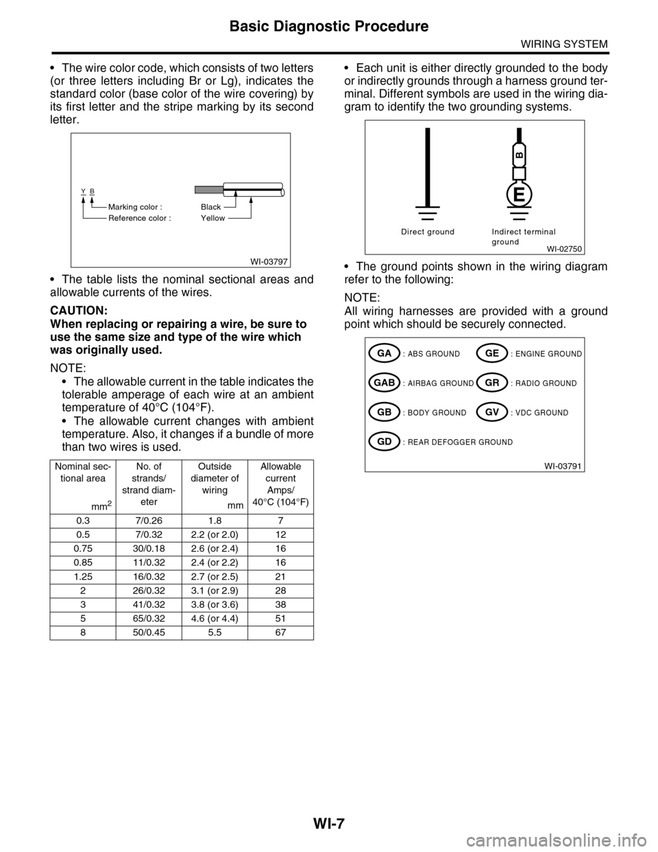
•The wire color code, which consists of two letters
(or three letters including Br or Lg), indicates the
standard color (base color of the wire covering) by
its first letter and the stripe marking by its second
letter.
•The table lists the nominal sectional areas and
allowable currents of the wires.
CAUTION:
When replacing or repairing a wire, be sure to
use the same size and type of the wire which
was originally used.
NOTE:
•The allowable current in the table indicates the
tolerable amperage of each wire at an ambient
temperature of 40°C (104°F).
•The allowable current changes with ambient
temperature. Also, it changes if a bundle of more
than two wires is used.
•Each unit is either directly grounded to the body
or indirectly grounds through a harness ground ter-
minal. Different symbols are used in the wiring dia-
gram to identify the two grounding systems.
•The ground points shown in the wiring diagram
refer to the following:
NOTE:
All wiring harnesses are provided with a ground
point which should be securely connected.
Nominal sec-
tional area
No. of
strands/
strand diam-
eter
Outside
diameter of
wiring
Allowable
current
Amps/
40°C (104°F)mm2mm
0.3 7/0.26 1.8 7
0.5 7/0.32 2.2 (or 2.0) 12
0.75 30/0.18 2.6 (or 2.4) 16
0.85 11/0.32 2.4 (or 2.2) 16
1.25 16/0.32 2.7 (or 2.5) 21
226/0.323.1 (or 2.9)28
341/0.323.8 (or 3.6)38
565/0.324.6 (or 4.4)51
850/0.455.5 67
WI-03797
YB
BlackMarking color :
Reference color : Yellow
WI-02750
Direct ground Indirect terminalground
B
WI-03791
: ABS GROUNDGA
: AIRBAG GROUNDGAB
: BODY GROUNDGB
: ENGINE GROUNDGE
: RADIO GROUNDGR
: VDC GROUNDGV
: REAR DEFOGGER GROUNDGD