2009 SUBARU TRIBECA brake rotor
[x] Cancel search: brake rotorPage 839 of 2453
DS-22
Rear Hub Unit Bearing
DRIVE SHAFT SYSTEM
NOTE:
If it is hard to remove, use the ST.
ST1 926470000 AXLE SHAFT PULLER
ST2 28099PA110 AXLE SHAFT PULLER
PLATE
B: INSTALLATION
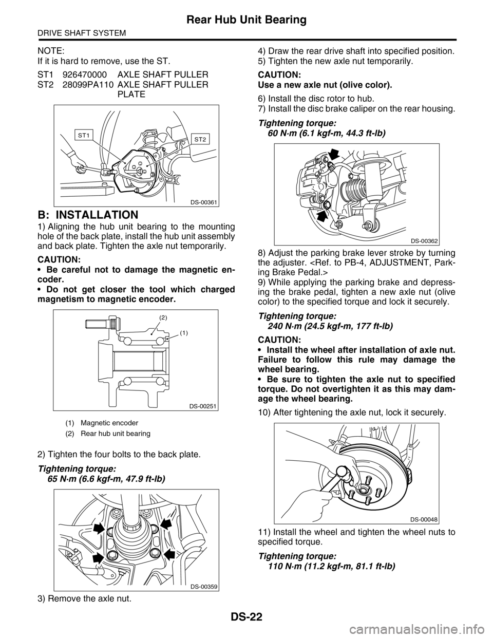
1) Aligning the hub unit bearing to the mounting
hole of the back plate, install the hub unit assembly
and back plate. Tighten the axle nut temporarily.
CAUTION:
•Be careful not to damage the magnetic en-
coder.
•Do not get closer the tool which charged
magnetism to magnetic encoder.
2) Tighten the four bolts to the back plate.
Tightening torque:
65 N·m (6.6 kgf-m, 47.9 ft-lb)
3) Remove the axle nut.
4) Draw the rear drive shaft into specified position.
5) Tighten the new axle nut temporarily.
CAUTION:
Use a new axle nut (olive color).
6) Install the disc rotor to hub.
7) Install the disc brake caliper on the rear housing.
Tightening torque:
60 N·m (6.1 kgf-m, 44.3 ft-lb)
8) Adjust the parking brake lever stroke by turning
the adjuster.
9) While applying the parking brake and depress-
ing the brake pedal, tighten a new axle nut (olive
color) to the specified torque and lock it securely.
Tightening torque:
240 N·m (24.5 kgf-m, 177 ft-lb)
CAUTION:
•Install the wheel after installation of axle nut.
Failure to follow this rule may damage the
wheel bearing.
•Be sure to tighten the axle nut to specified
torque. Do not overtighten it as this may dam-
age the wheel bearing.
10) After tightening the axle nut, lock it securely.
11) Install the wheel and tighten the wheel nuts to
specified torque.
Tightening torque:
110 N·m (11.2 kgf-m, 81.1 ft-lb)
(1) Magnetic encoder
(2) Rear hub unit bearing
ST2ST1
DS-00361
DS-00251
(2)
(1)
DS-00359
DS-00362
DS-00048
Page 878 of 2453

PB-7
Parking Brake Assembly (Rear Disc Brake)
PARKING BRAKE
4. Parking Brake Assembly
(Rear Disc Brake)
A: REMOVAL
1) Release the parking brake.
2) Lift-up the vehicle, and then remove the rear
wheels.
3) Remove the two mounting bolts and remove the
disc brake caliper assembly.
4) Suspend the rear disk brake caliper assembly so
that the brake hose is not stretched.
5) Remove the rear disk brake rotor.
NOTE:
If the disc rotor is difficult to remove, try the follow-
ing two methods in order.
(1) Turn the adjusting screw using a flat tip
screwdriver until the brake shoe moves ade-
quately away from the disc rotor.
(2) If disc rotor is seized up on the hub, drive the
disc rotor out by pushing two 8-mm bolts in
holes B on the rotor.
6) Remove the shoe return spring.
7) Remove the brake shoe cup and brake shoe
spring, then remove the primary brake shoe.
8) Remove the strut and strut spring.
9) Remove the adjuster assembly.
10) Remove the brake shoe cup and brake shoe
spring, then remove the secondary brake shoe.
(1) Adjuster
(2) Adjusting hole cover (rubber)
(3) Flat tip screwdriver
(4) Disc rotor
PB-00092
(1)
(4)
(2)
(3)
PB-00094(1) Brake shoe cup
(2) Primary brake shoe
B
A
BR-00018
PB-00095
(1)
(2)
PB-00096
Page 879 of 2453
PB-8
Parking Brake Assembly (Rear Disc Brake)
PARKING BRAKE
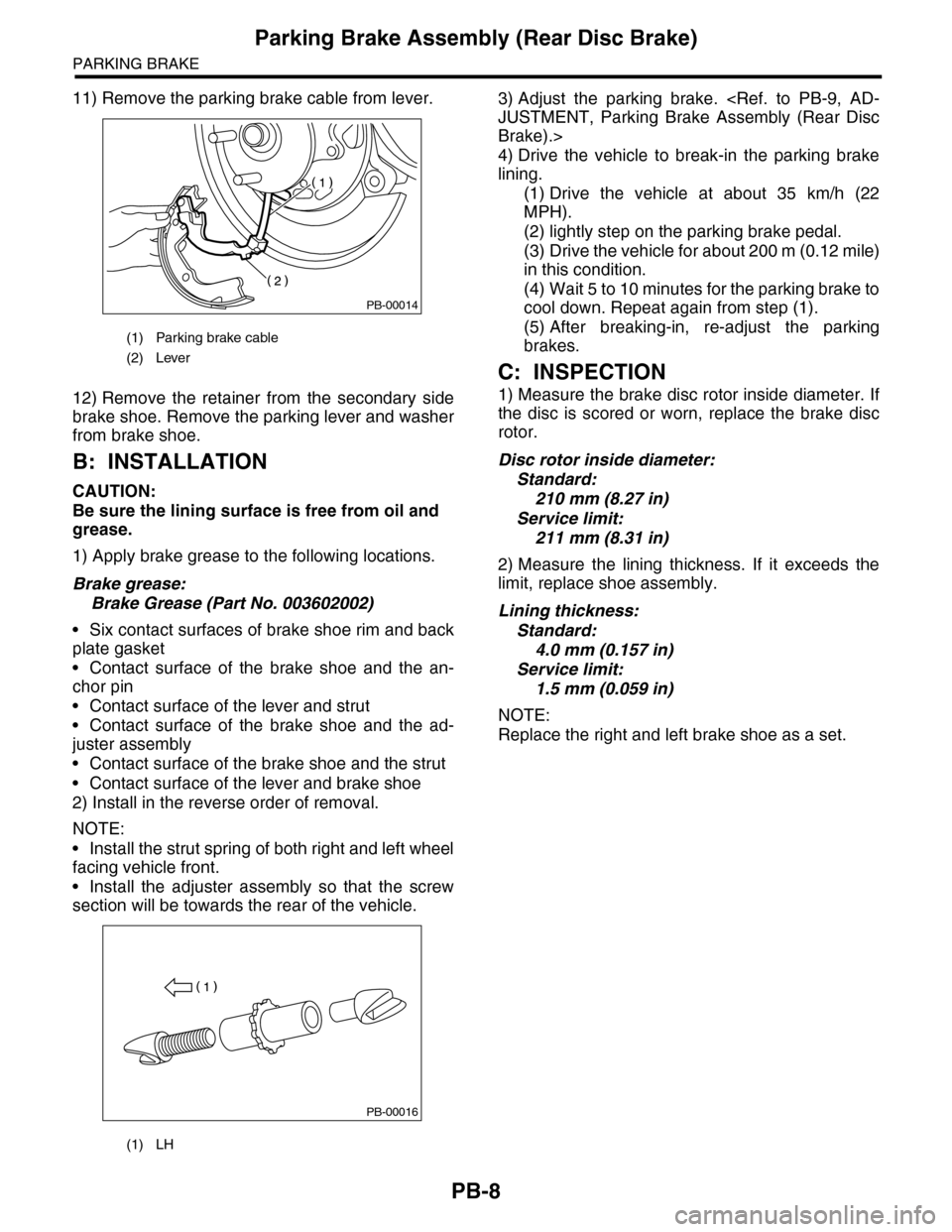
11) Remove the parking brake cable from lever.
12) Remove the retainer from the secondary side
brake shoe. Remove the parking lever and washer
from brake shoe.
B: INSTALLATION
CAUTION:
Be sure the lining surface is free from oil and
grease.
1) Apply brake grease to the following locations.
Brake grease:
Brake Grease (Part No. 003602002)
•Six contact surfaces of brake shoe rim and back
plate gasket
•Contact surface of the brake shoe and the an-
chor pin
•Contact surface of the lever and strut
•Contact surface of the brake shoe and the ad-
juster assembly
•Contact surface of the brake shoe and the strut
•Contact surface of the lever and brake shoe
2) Install in the reverse order of removal.
NOTE:
•Install the strut spring of both right and left wheel
facing vehicle front.
•Install the adjuster assembly so that the screw
section will be towards the rear of the vehicle.
3) Adjust the parking brake.
Brake).>
4) Drive the vehicle to break-in the parking brake
lining.
(1) Drive the vehicle at about 35 km/h (22
MPH).
(2) lightly step on the parking brake pedal.
(3) Drive the vehicle for about 200 m (0.12 mile)
in this condition.
(4) Wait 5 to 10 minutes for the parking brake to
cool down. Repeat again from step (1).
(5) After breaking-in, re-adjust the parking
brakes.
C: INSPECTION
1) Measure the brake disc rotor inside diameter. If
the disc is scored or worn, replace the brake disc
rotor.
Disc rotor inside diameter:
Standard:
210 mm (8.27 in)
Service limit:
211 mm (8.31 in)
2) Measure the lining thickness. If it exceeds the
limit, replace shoe assembly.
Lining thickness:
Standard:
4.0 mm (0.157 in)
Service limit:
1.5 mm (0.059 in)
NOTE:
Replace the right and left brake shoe as a set.
(1) Parking brake cable
(2) Lever
(1) LH
PB-00014
PB-00016
Page 880 of 2453
PB-9
Parking Brake Assembly (Rear Disc Brake)
PARKING BRAKE
D: ADJUSTMENT
1. SHOE CLEARANCE
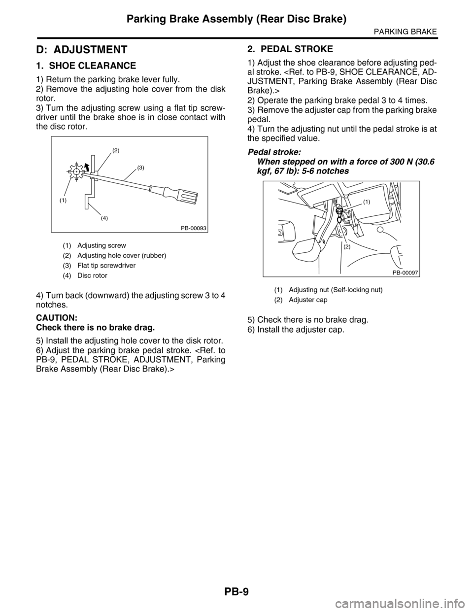
1) Return the parking brake lever fully.
2) Remove the adjusting hole cover from the disk
rotor.
3) Turn the adjusting screw using a flat tip screw-
driver until the brake shoe is in close contact with
the disc rotor.
4) Turn back (downward) the adjusting screw 3 to 4
notches.
CAUTION:
Check there is no brake drag.
5) Install the adjusting hole cover to the disk rotor.
6) Adjust the parking brake pedal stroke.
Brake Assembly (Rear Disc Brake).>
2. PEDAL STROKE
1) Adjust the shoe clearance before adjusting ped-
al stroke.
Brake).>
2) Operate the parking brake pedal 3 to 4 times.
3) Remove the adjuster cap from the parking brake
pedal.
4) Turn the adjusting nut until the pedal stroke is at
the specified value.
Pedal stroke:
When stepped on with a force of 300 N (30.6
kgf, 67 lb): 5-6 notches
5) Check there is no brake drag.
6) Install the adjuster cap.
(1) Adjusting screw
(2) Adjusting hole cover (rubber)
(3) Flat tip screwdriver
(4) Disc rotor
(1)
(4)
(2)
(3)
PB-00093
(1) Adjusting nut (Self-locking nut)
(2) Adjuster cap
PB-00097
(1)
(2)
Page 1001 of 2453
VDC(diag)-9
General Description
VEHICLE DYNAMICS CONTROL (VDC) (DIAGNOSTICS)
3. General Description
A: CAUTION
1. SRS AIRBAG SYSTEM
Airbag system wiring harness is routed near the
ABS wheel speed sensor and VDCCM&H/U.
CAUTION:
•All airbag system wiring harness and con-
nectors are colored yellow. Do not use the elec-
trical test equipment on these circuits.
•Be careful not to damage the airbag system
wiring harness when servicing the ABS wheel
speed sensor and VDCCM&H/U.
B: INSPECTION
Before performing diagnosis, check the following
items which might affect VDC problems.
1. BATTERY
Measure the battery voltage and check electrolyte.
Standard voltage: 12 V or more
Specific gravity: 1.260 or more
2. GROUND
Check the tightening torque of ground (GB-7) bolt
of VDC.
Tightening torque:
13 N·m (1.3 kgf-m, 9.6 ft-lb)
3. BRAKE FLUID
1) Check the brake fluid level.
2) Check the brake fluid for leaks.
4. HYDRAULIC UNIT
Check the hydraulic unit.
•With brake tester
TESTER, INSPECTION, VDC Control Module &
Hydraulic Control Unit (VDCCM&H/U).>
•Without brake tester
USING A PRESSURE GAUGE, INSPECTION,
VDC Control Module & Hydraulic Control Unit (VD-
CCM&H/U).>
5. BRAKE DRAG
Check for brake drag.
6. BRAKE PAD AND ROTOR
Check the brake pad and rotor.
•Front
•Rear
7. TIRE
Check the tire specifications, tire wear and air pres-
sure.
Page 1079 of 2453
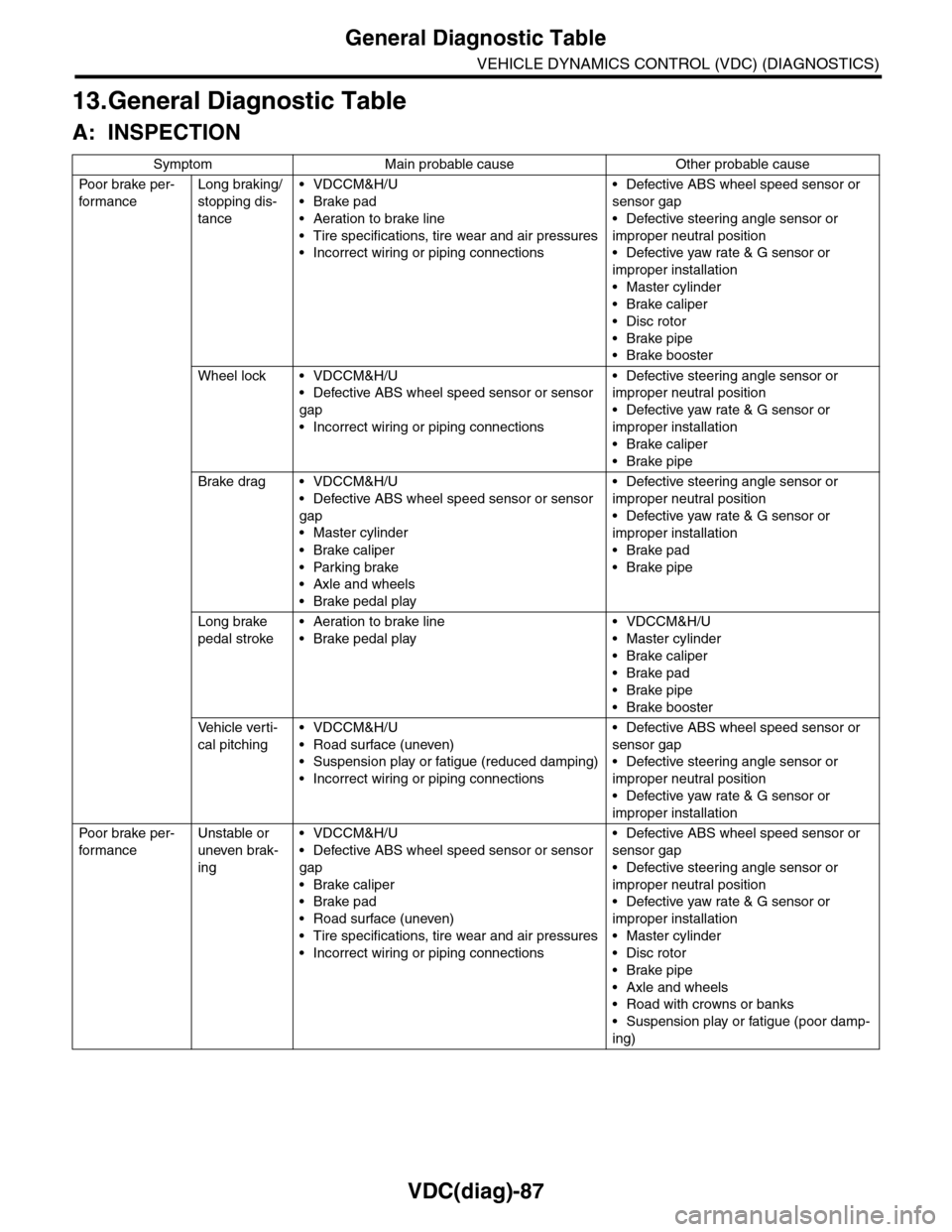
VDC(diag)-87
General Diagnostic Table
VEHICLE DYNAMICS CONTROL (VDC) (DIAGNOSTICS)
13.General Diagnostic Table
A: INSPECTION
Symptom Main probable cause Other probable cause
Po or b rake pe r -
for mance
Long braking/
stopping dis-
tance
•VDCCM&H/U
•Brake pad
•Aeration to brake line
•Tire specifications, tire wear and air pressures
•Incorrect wiring or piping connections
•Defective ABS wheel speed sensor or
sensor gap
•Defective steering angle sensor or
improper neutral position
•Defective yaw rate & G sensor or
improper installation
•Master cylinder
•Brake caliper
•Disc rotor
•Brake pipe
•Brake booster
Wheel lock • VDCCM&H/U
•Defective ABS wheel speed sensor or sensor
gap
•Incorrect wiring or piping connections
•Defective steering angle sensor or
improper neutral position
•Defective yaw rate & G sensor or
improper installation
•Brake caliper
•Brake pipe
Brake drag • VDCCM&H/U
•Defective ABS wheel speed sensor or sensor
gap
•Master cylinder
•Brake caliper
•Parking brake
•Axle and wheels
•Brake pedal play
•Defective steering angle sensor or
improper neutral position
•Defective yaw rate & G sensor or
improper installation
•Brake pad
•Brake pipe
Long brake
pedal stroke
•Aeration to brake line
•Brake pedal play
•VDCCM&H/U
•Master cylinder
•Brake caliper
•Brake pad
•Brake pipe
•Brake booster
Ve h i c l e v e r t i -
cal pitching
•VDCCM&H/U
•Road surface (uneven)
•Suspension play or fatigue (reduced damping)
•Incorrect wiring or piping connections
•Defective ABS wheel speed sensor or
sensor gap
•Defective steering angle sensor or
improper neutral position
•Defective yaw rate & G sensor or
improper installation
Po or b rake pe r -
for mance
Unstable or
uneven brak-
ing
•VDCCM&H/U
•Defective ABS wheel speed sensor or sensor
gap
•Brake caliper
•Brake pad
•Road surface (uneven)
•Tire specifications, tire wear and air pressures
•Incorrect wiring or piping connections
•Defective ABS wheel speed sensor or
sensor gap
•Defective steering angle sensor or
improper neutral position
•Defective yaw rate & G sensor or
improper installation
•Master cylinder
•Disc rotor
•Brake pipe
•Axle and wheels
•Road with crowns or banks
•Suspension play or fatigue (poor damp-
ing)
Page 1080 of 2453
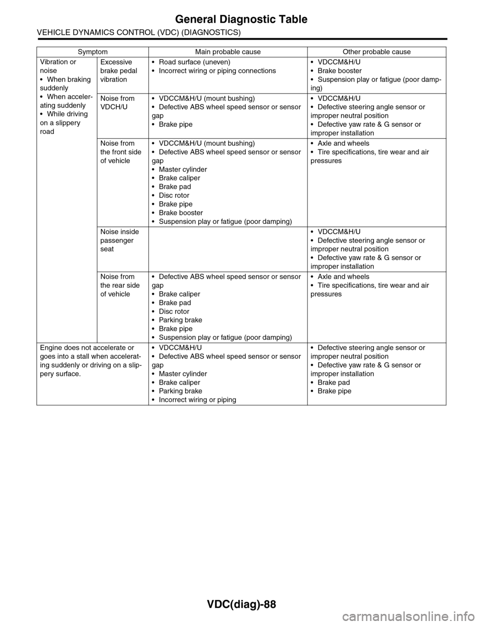
VDC(diag)-88
General Diagnostic Table
VEHICLE DYNAMICS CONTROL (VDC) (DIAGNOSTICS)
Vibration or
noise
•When braking
suddenly
•When acceler-
ating suddenly
•While driving
on a slippery
road
Excessive
brake pedal
vibration
•Road surface (uneven)
•Incorrect wiring or piping connections
•VDCCM&H/U
•Brake booster
•Suspension play or fatigue (poor damp-
ing)
Noise from
VDCH/U
•VDCCM&H/U (mount bushing)
•Defective ABS wheel speed sensor or sensor
gap
•Brake pipe
•VDCCM&H/U
•Defective steering angle sensor or
improper neutral position
•Defective yaw rate & G sensor or
improper installation
Noise from
the front side
of vehicle
•VDCCM&H/U (mount bushing)
•Defective ABS wheel speed sensor or sensor
gap
•Master cylinder
•Brake caliper
•Brake pad
•Disc rotor
•Brake pipe
•Brake booster
•Suspension play or fatigue (poor damping)
•Axle and wheels
•Tire specifications, tire wear and air
pressures
Noise inside
passenger
seat
•VDCCM&H/U
•Defective steering angle sensor or
improper neutral position
•Defective yaw rate & G sensor or
improper installation
Noise from
the rear side
of vehicle
•Defective ABS wheel speed sensor or sensor
gap
•Brake caliper
•Brake pad
•Disc rotor
•Parking brake
•Brake pipe
•Suspension play or fatigue (poor damping)
•Axle and wheels
•Tire specifications, tire wear and air
pressures
Engine does not accelerate or
goes into a stall when accelerat-
ing suddenly or driving on a slip-
pery surface.
•VDCCM&H/U
•Defective ABS wheel speed sensor or sensor
gap
•Master cylinder
•Brake caliper
•Parking brake
•Incorrect wiring or piping
•Defective steering angle sensor or
improper neutral position
•Defective yaw rate & G sensor or
improper installation
•Brake pad
•Brake pipe
Symptom Main probable cause Other probable cause
Page 1081 of 2453
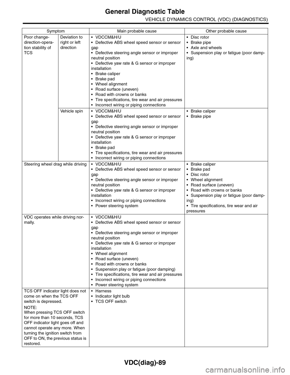
VDC(diag)-89
General Diagnostic Table
VEHICLE DYNAMICS CONTROL (VDC) (DIAGNOSTICS)
Po or ch a ng e -
direction-opera-
tion stability of
TCS
Deviation to
right or left
direction
•VDCCM&H/U
•Defective ABS wheel speed sensor or sensor
gap
•Defective steering angle sensor or improper
neutral position
•Defective yaw rate & G sensor or improper
installation
•Brake caliper
•Brake pad
•Wheel alignment
•Road surface (uneven)
•Road with crowns or banks
•Tire specifications, tire wear and air pressures
•Incorrect wiring or piping connections
•Disc rotor
•Brake pipe
•Axle and wheels
•Suspension play or fatigue (poor damp-
ing)
Ve h i c l e s p i n • V D C C M & H / U
•Defective ABS wheel speed sensor or sensor
gap
•Defective steering angle sensor or improper
neutral position
•Defective yaw rate & G sensor or improper
installation
•Brake pad
•Tire specifications, tire wear and air pressures
•Incorrect wiring or piping connections
•Brake caliper
•Brake pipe
Steering wheel drag while driving • VDCCM&H/U
•Defective ABS wheel speed sensor or sensor
gap
•Defective steering angle sensor or improper
neutral position
•Defective yaw rate & G sensor or improper
installation
•Incorrect wiring or piping connections
•Power steering system
•Brake caliper
•Brake pad
•Disc rotor
•Wheel alignment
•Road surface (uneven)
•Road with crowns or banks
•Suspension play or fatigue (poor damp-
ing)
•Tire specifications, tire wear and air
pressures
VDC operates while driving nor-
mally.
•VDCCM&H/U
•Defective ABS wheel speed sensor or sensor
gap
•Defective steering angle sensor or improper
neutral position
•Defective yaw rate & G sensor or improper
installation
•Wheel alignment
•Road surface (uneven)
•Road with crowns or banks
•Suspension play or fatigue (poor damping)
•Tire specifications, tire wear and air pressures
•Incorrect wiring or piping connections
•Power steering system
TCS OFF indicator light does not
come on when the TCS OFF
switch is depressed.
NOTE:When pressing TCS OFF switch
for more than 10 seconds, TCS
OFF indicator light goes off and
cannot operate any more. When
turning the ignition switch from
OFF to ON, the previous status is
restored.
•Harness
•Indicator light bulb
•TCS OFF switch
Symptom Main probable cause Other probable cause