Page 282 of 2453

EI-40
Instrument Panel Assembly
EXTERIOR/INTERIOR TRIM
17.Instrument Panel Assembly
A: REMOVAL
CAUTION:
Take care of the following when removing the
instrument panel from the vehicle body.
•Refer to “CAUTION” of “General Description”
before starting the work.
TION, General Description.>
•Be sure to disconnect each harness connec-
tor. Applying excessive pulling force may dam-
age the harness.
•Be careful to the harness of airbag system.
Damage of the harness may cause the air bag
system malfunction.
•Take care not to damage the interior trims
when removing the instrument panel from the
vehicle body.
NOTE:
•Putting alignment marks to each connector as
necessary facilitates the reassembly work.
•When storing the removed instrument panel, be
sure to prepare a table or the like to put the instru-
ment panel on in order to prevent damage.
1. INSTRUMENT PANEL UPPER
1) Disconnect the ground cable from battery and
wait for at least 20 seconds before starting work.
2) Remove the console box.
MOVAL, Console Box.>
3) Remove the instrument panel lower cover.
to EI-36, REMOVAL, Instrument Panel Lower Cov-
er.>
4) Remove the glove box.
AL, Glove Box.>
5) Remove the center console.
MOVAL, Center Console.>
6) Remove the audio unit.
MOVAL, Audio.>
7) Remove the combination meter assembly.
to IDI-11, REMOVAL, Combination Meter.>
8) Remove the upper grille.
PER GRILL, REMOVAL, Air Vent Grille.>
9) Remove the multi function display or navigation
monitor, and warning box.
MOVAL, Navigation Display.>
10) Remove the front pillar upper trim.
43, REMOVAL, Side Trim.>
11) Remove the mounting bolts of the passenger’s
side air bag module.
12) Remove the following screws.
•In combination meter house
•At the sides (left and right) of instrument panel
•Instrument panel center
EI-01327
EI-01328
EI-01330
EI-01329
Page 283 of 2453

EI-41
Instrument Panel Assembly
EXTERIOR/INTERIOR TRIM
13) Make sure that the instrument panel upper is
removed from the steering support beam
14) Disconnect the connectors, and remove the in-
strument panel from vehicle body.
15) Remove the heater vent duct.
REMOVAL, Heater Vent Duct.>
16) Remove the air vent grille.
MOVAL, Air Vent Grille.>
17) Remove the passenger airbag module.
to AB-16, REMOVAL, Passenger’s Airbag Mod-
ule.>
2. STEERING SUPPORT BEAM
1) Remove the instrument panel upper.
2) Remove the bolts, and then remove the knee
guard plate.
3) Remove the steering shaft from the steering
support beam.
Steering Column.>
4) Remove the bolts and remove the steering sup-
port beam.
3. INSTRUMENT PANEL ASSEMBLY
1) Disconnect the ground cable from battery and
wait for at least 20 seconds before starting work.
2) Remove the console box.
MOVAL, Console Box.>
3) Remove the instrument panel lower cover.
to EI-36, REMOVAL, Instrument Panel Lower Cov-
er.>
4) Remove the glove box.
AL, Glove Box.>
5) Remove the center console.
MOVAL, Center Console.>
6) Remove the front pillar upper trim.
43, REMOVAL, Side Trim.>
7) Remove the steering shaft from the steering
support beam.
Steering Column.>
8) Disconnect the connectors, and remove the in-
strument panel from vehicle body.
9) Remove the bolts and remove the steering sup-
port beam.
NOTE:
For positions of the mounting bolt of steering sup-
port beam, refer to the removal procedure of the
steering support beam.
10) Make sure that the each harness connector is
disconnected, and remove the instrument panel as-
sembly from the vehicle body.
NOTE:
Remove the passenger’s side door trim to facilitate
the work.
EI-01331
EI-01332
Page 284 of 2453

EI-42
Instrument Panel Assembly
EXTERIOR/INTERIOR TRIM
B: INSTALLATION
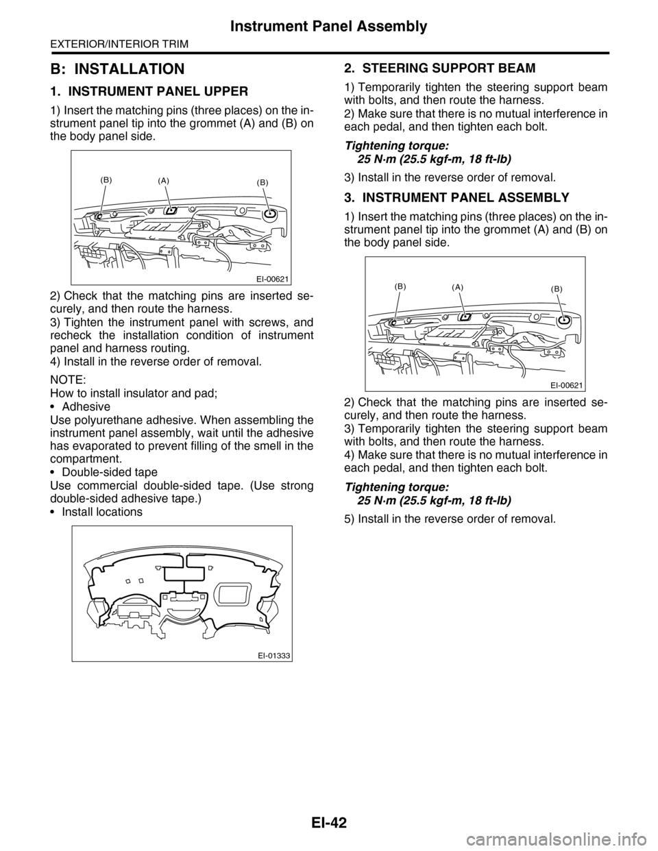
1. INSTRUMENT PANEL UPPER
1) Insert the matching pins (three places) on the in-
strument panel tip into the grommet (A) and (B) on
the body panel side.
2) Check that the matching pins are inserted se-
curely, and then route the harness.
3) Tighten the instrument panel with screws, and
recheck the installation condition of instrument
panel and harness routing.
4) Install in the reverse order of removal.
NOTE:
How to install insulator and pad;
•Adhesive
Use polyurethane adhesive. When assembling the
instrument panel assembly, wait until the adhesive
has evaporated to prevent filling of the smell in the
compartment.
•Double-sided tape
Use commercial double-sided tape. (Use strong
double-sided adhesive tape.)
•Install locations
2. STEERING SUPPORT BEAM
1) Temporarily tighten the steering support beam
with bolts, and then route the harness.
2) Make sure that there is no mutual interference in
each pedal, and then tighten each bolt.
Tightening torque:
25 N·m (25.5 kgf-m, 18 ft-lb)
3) Install in the reverse order of removal.
3. INSTRUMENT PANEL ASSEMBLY
1) Insert the matching pins (three places) on the in-
strument panel tip into the grommet (A) and (B) on
the body panel side.
2) Check that the matching pins are inserted se-
curely, and then route the harness.
3) Temporarily tighten the steering support beam
with bolts, and then route the harness.
4) Make sure that there is no mutual interference in
each pedal, and then tighten each bolt.
Tightening torque:
25 N·m (25.5 kgf-m, 18 ft-lb)
5) Install in the reverse order of removal.
EI-00621
(B)(B)(A)
EI-01333
EI-00621
(B)(B)(A)
Page 292 of 2453
EI-50
Roof Trim
EXTERIOR/INTERIOR TRIM
23.Roof Trim
A: REMOVAL
1) Disconnect the ground cable from battery.
2) Remove the spot map light.
MOVAL, Spot Map Light.>
3) Remove the room light or rear entertainment
(model with rear entertainment system).
LI-30, REMOVAL, Room Light.>
4) Remove the sun visor.
AL, Sun Visor.>
5) Remove the assist grip.
AL, Assist Grip.>
6) Remove the front pillar upper trim and center pil-
lar upper trim.
Trim.>
7) Remove the rear quarter upper trim.
45, REMOVAL, Rear Quarter Trim.>
8) Remove the sunroof opening trim.
9) Remove the clips and each harness, pull out the
rear center seat belt, and remove the roof trim.
B: INSTALLATION
Install in the reverse order of removal.
EI-00501
EI-01354
Page 301 of 2453
GW-6
Power Window System
GLASS/WINDOWS/MIRRORS
2. Power Window System
A: WIRING DIAGRAM
B: INSPECTION
Symptom Repair order
All power windows do not operate.
1. Fuse (SBF-4)
2. Power window circuit breaker
3. Power window relay
4. Wiring Harness
5. Body integrated unit
Par ticular window does not operate.
1. Power window main switch
2. Power window sub switch
3. Power window motor
4. Wiring Harness
“Window Lock” does not operate. Power window main switch
Page 302 of 2453

GW-7
Power Window Control Switch
GLASS/WINDOWS/MIRRORS
3. Power Window Control
Switch
A: REMOVAL
1. MAIN SWITCH
1) Disconnect the ground cable from battery.
2) Peel the cover inside the hand grip, and remove
the screw.
3) Remove the power window switch cover assem-
bly.
4) Disconnect the harness connector.
5) Remove the clip, and remove the power window
main switch assembly.
2. SUB SWITCH
1) Disconnect the ground cable from battery.
2) Peel the cover inside the hand grip, and remove
the screw.
3) Remove the power window switch cover assem-
bly.
4) Disconnect the connector.
5) Detach the claw and remove the power window
sub switch.
B: INSTALLATION
Install in the reverse order of removal.
C: INSPECTION
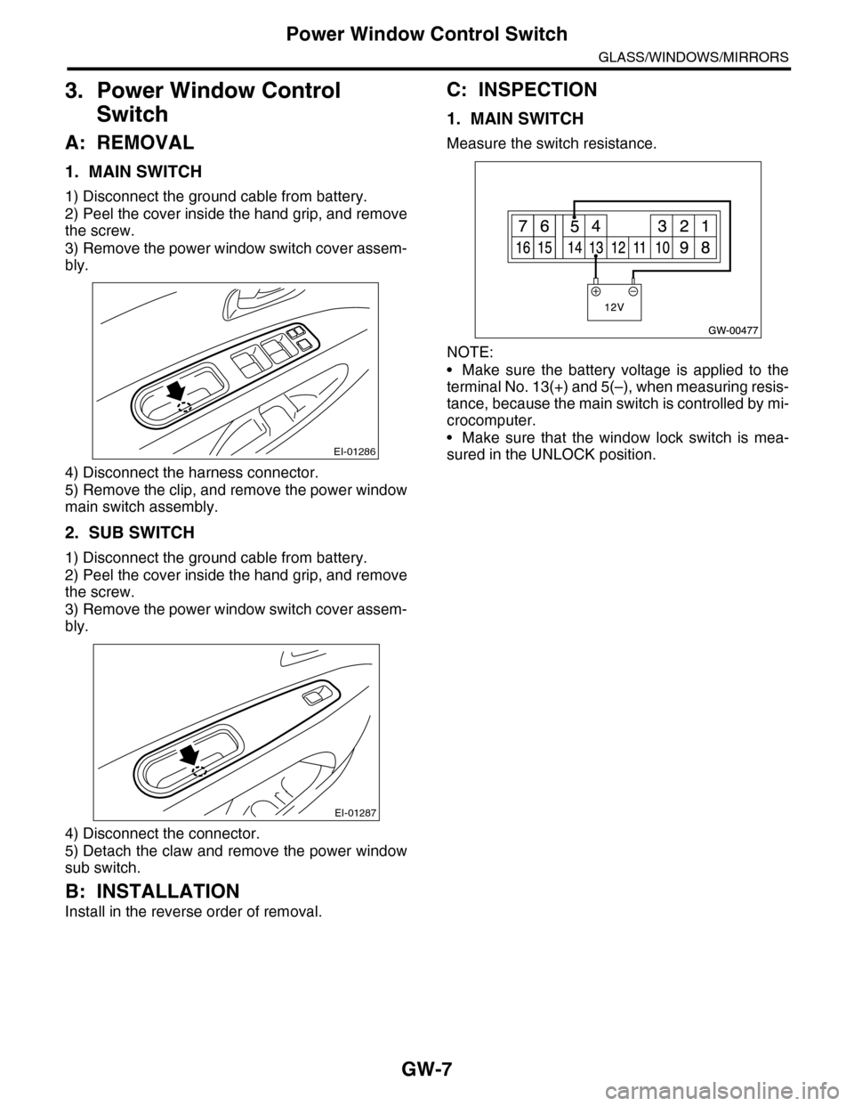
1. MAIN SWITCH
Measure the switch resistance.
NOTE:
•Make sure the battery voltage is applied to the
terminal No. 13(+) and 5(–), when measuring resis-
tance, because the main switch is controlled by mi-
crocomputer.
•Make sure that the window lock switch is mea-
sured in the UNLOCK position.EI-01286
EI-01287
Page 306 of 2453
GW-11
Remote Control Mirror System
GLASS/WINDOWS/MIRRORS
6. Remote Control Mirror System
A: WIRING DIAGRAM
B: INSPECTION
Symptom Repair order
All function does not operate.
1. Fuse (F/B No. 6)
2. Mirror switch
3. Wiring harness
One side of the mirror motor does not operate.
1. Mirror switch
2. Mirror motor
3. Wiring harness
Mirror heater does not operate.
1. Mirror switch
2. Mirror heater
3. Wiring harness
Page 319 of 2453
GW-24
Rear Window Defogger System
GLASS/WINDOWS/MIRRORS
16.Rear Window Defogger System
A: WIRING DIAGRAM
B: INSPECTION
NOTE:
Rear window defogger system can be customized on the Subaru Select Monitor.
Symptom Repair order
Rear window defogger does not operate.
1. Fuse (M/B No. 10) (F/B No. 22)
2. Rear defogger relay
3. Defogger switch
4. Rear defogger condenser
5. Defogger wire
6. Wiring harness
7. Body integrated unit
System name Initial setting Customize setting
Rear window defogger timer OFF after 15 min.Repeat 15 min. operation and
2 min. stop.