2009 SUBARU TRIBECA ecm
[x] Cancel search: ecmPage 782 of 2453

BVC(diag)-27
Diagnostic Procedure with Diagnostic Trouble Code (DTC)
BRAKE VACUUM CONTROL (BVC) (DIAGNOSTICS)
Step Check Yes No
1CHECK BRAKE VACUUM PUMP RELAY.
1) Turn the ignition switch to OFF.
2) Remove the brake vacuum pump relay from
the relay box.
3) Connect the battery to terminals No. 1 and
No. 3 of the brake vacuum pump relay.
4) Measure the resistance between the brake
vacuum pump relay terminals.
Te r m i n a l s
No. 4 — No. 5:
Is the resistance less than 1
Ω?
Go to step 2.Replace the brake
vacuum pump
relay.
2CHECK BRAKE VACUUM PUMP RELAY
POWER SUPPLY.
1) Turn the ignition switch to ON.
2) Measure the voltage between brake vac-
uum pump relay connector and chassis
ground.
Connector & terminal
(VC2) No. 1 (+) — Chassis ground (–):
(VC2) No. 4 (+) — Chassis ground (–):
Is the voltage more than 10 V? Go to step 3.Repair the open or
ground short cir-
cuit of power sup-
ply circuit.
3CHECK HARNESS BETWEEN ECM AND
BRAKE VACUUM PUMP RELAY CONNEC-
TOR.
1) Turn the ignition switch to OFF.
2) Disconnect the connector of ECM.
3) Measure the resistance of the harness
between ECM and the brake vacuum pump
relay connector.
Connector & terminal
(B136) No. 8 — (VC2) No. 3:
(B135) No. 25 — (VC2) No. 5:
Is the resistance less than 1
Ω?
Go to step 4.Repair the open
circuit of harness
between ECM and
the brake vacuum
pump relay con-
nector.
4CHECK HARNESS BETWEEN THE BRAKE
VACUUM PUMP AND BRAKE VACUUM
PUMP RELAY CONNECTOR.
1) Turn the ignition switch to OFF.
2) Disconnect the brake vacuum pump con-
nector.
3) Measure the resistance of the harness
between the brake vacuum pump and brake
vacuum pump relay connector.
Connector & terminal
(VC2) No. 5 — (B417) No. 1:
Is the resistance less than 1
Ω?
Go to step 5.Repair the open
circuit of the har-
ness between the
brake vacuum
pump and the
brake vacuum
pump relay con-
nector.
5CHECK ECM.
1) Connect the brake vacuum pump relay.
2) Connect the connectors to the brake vac-
uum pump and ECM.
3) Turn the ignition switch to ON.
4) Measure the voltage between ECM and
chassis ground.
Connector & terminal
(B136) No. 8 — Chassis ground (–):
Is the voltage more than 10 V? Replace the ECM.
Engine Control
Module (ECM).>
Te m p o r a r y p o o r
contact occurs.
Page 783 of 2453

BVC(diag)-28
Diagnostic Procedure with Diagnostic Trouble Code (DTC)
BRAKE VACUUM CONTROL (BVC) (DIAGNOSTICS)
F: DTC 23 PUMP CONTINUOUS OPERATION
DTC DETECTING CONDITION:
Brake vacuum pump malfunction
TROUBLE SYMPTOM:
Break vacuum pump operates continuously.
WIRING DIAGRAM:
BR-00528
2
1
B25B
B422
1234
B432
2
1
4
36
5
8
7
B432
SBF HOLDER
3
7
14
21
53
43
VC2
VC3
B422
B422
VC3
RELAY BOX(VACUUMPUMP RELAY)
B417
VAC U U MPUMP
26
41
B47
MAINRELAY
B411
VAC U U M S E N S O RECM
A: B134B: B135C: B136
C23B30B22A27C8312
JOINT CONNECTOR
B424
**
B417B411
213
B: C:B135
5672134
29
101112131415252416
30
98171819202821222332312627333435
B136
16101112131415252430
9871718192028212223293231
123456
2726333435
VC2
A:B134
85610 11 12 13 14 157213416
3019 20 2228 29
91718252123 24323126 2733 34
B424
34561278
(BROWN)
21
5436
B47
* : TERMINAL NO. OPTIONAL ARRANGEMENT
21
SBF-7BATTERY
30A
3412
5
8967
10131211
14
Page 784 of 2453

BVC(diag)-29
Diagnostic Procedure with Diagnostic Trouble Code (DTC)
BRAKE VACUUM CONTROL (BVC) (DIAGNOSTICS)
Step Check Yes No
1CHECK BRAKE VACUUM HOSE.
1) Turn the ignition switch to OFF.
2) Check that status of the brake vacuum
hose connection.
Is the brake vacuum hose con-
nected firmly?
Go to step 2.Connect the brake
vacuum hose.
2CHECK BRAKE VACUUM HOSE.
1) Turn the ignition switch to ON and start
engine.
2) Check for leakage from the brake vacuum
hose.
Is there a leak from the brake
vacuum hose?
Replace the brake
vacuum hose.
Go to step 3.
3CHECK BRAKE VACUUM PUMP RELAY.
1) Turn the ignition switch to OFF.
2) Remove the brake vacuum pump relay from
the relay box.
3) Connect the battery to terminals No. 1 and
No. 3 of the brake vacuum pump relay.
4) Measure the resistance between the brake
vacuum pump relay terminals.
Te r m i n a l s
No. 4 — No. 5:
Is the resistance less than 1
Ω?
Go to step 4.Replace the brake
vacuum pump
relay.
4CHECK BRAKE VACUUM PUMP RELAY
POWER SUPPLY.
1) Turn the ignition switch to ON.
2) Measure the voltage between brake vac-
uum pump relay connector and chassis
ground.
Connector & terminal
(VC2) No. 1 (+) — Chassis ground (–):
(VC2) No. 4 (+) — Chassis ground (–):
Is the voltage more than 10 V? Go to step 5.Repair the open or
ground short cir-
cuit of power sup-
ply circuit.
5CHECK HARNESS BETWEEN ECM AND
BRAKE VACUUM PUMP RELAY CONNEC-
TOR.
1) Turn the ignition switch to OFF.
2) Disconnect the connector of ECM.
3) Measure the resistance of the harness
between ECM and the brake vacuum pump
relay connector.
Connector & terminal
(B136) No. 8 — (VC2) No. 3:
(B135) No. 25 — (VC2) No. 5:
Is the resistance less than 1
Ω?
Go to step 6.Repair the open
circuit of harness
between ECM and
the brake vacuum
pump relay con-
nector.
6CHECK HARNESS BETWEEN THE BRAKE
VACUUM PUMP AND BRAKE VACUUM
PUMP RELAY CONNECTOR.
1) Turn the ignition switch to OFF.
2) Disconnect the brake vacuum pump con-
nector.
3) Measure the resistance of the harness
between the brake vacuum pump and brake
vacuum pump relay connector.
Connector & terminal
(VC2) No. 5 — (B417) No. 1:
Is the resistance less than 1
Ω?
Go to step 7.Repair the open
circuit of the har-
ness between the
brake vacuum
pump and the
brake vacuum
pump relay con-
nector.
7CHECK ECM.
1) Connect the brake vacuum pump relay.
2) Connect the connectors to the brake vac-
uum pump and ECM.
3) Turn the ignition switch to ON.
4) Measure the voltage between ECM and
chassis ground.
Connector & terminal
(B136) No. 8 — Chassis ground (–):
Is the voltage more than 10 V? Replace the ECM.
Engine Control
Module (ECM).>
Te m p o r a r y p o o r
contact occurs.
Page 1003 of 2453
VDC(diag)-11
Electrical Component Location
VEHICLE DYNAMICS CONTROL (VDC) (DIAGNOSTICS)
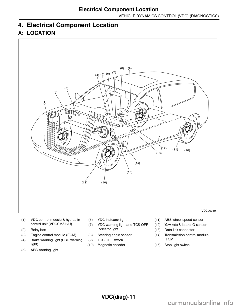
4. Electrical Component Location
A: LOCATION
(1) VDC control module & hydraulic
control unit (VDCCM&H/U)
(6) VDC indicator light (11) ABS wheel speed sensor
(7) VDC warning light and TCS OFF
indicator light
(12) Yaw rate & lateral G sensor
(2) Relay box (13) Data link connector
(3) Engine control module (ECM) (8) Steering angle sensor (14) Transmission control module
(TCM)(4) Brake warning light (EBD warning
light)
(9) TCS OFF switch
(10) Magnetic encoder (15) Stop light switch
(5) ABS warning light
(4)(5)(6)(7)
(8)
(1)
(2)
(3)
(15)
(14)
(12)
(13)
(11)(10)
(11)(10)
(9)
VDC00359
Page 1007 of 2453
VDC(diag)-15
Control Module I/O Signal
VEHICLE DYNAMICS CONTROL (VDC) (DIAGNOSTICS)
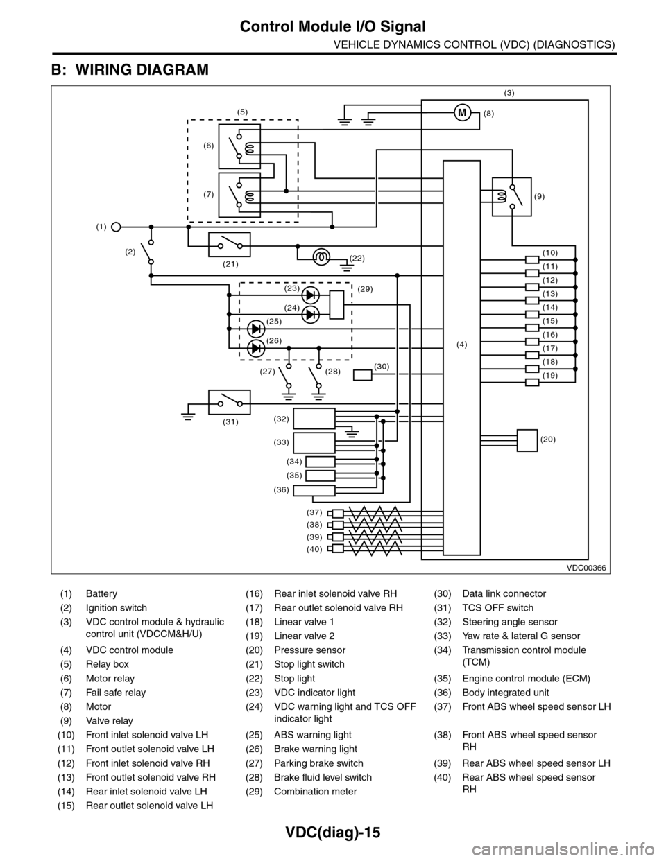
B: WIRING DIAGRAM
(1) Battery (16) Rear inlet solenoid valve RH (30) Data link connector
(2) Ignition switch (17) Rear outlet solenoid valve RH (31) TCS OFF switch
(3) VDC control module & hydraulic
control unit (VDCCM&H/U)
(18) Linear valve 1 (32) Steering angle sensor
(19) Linear valve 2 (33) Yaw rate & lateral G sensor
(4) VDC control module (20) Pressure sensor (34)
Tr a n s m i s s i o n c o n t r o l m o d u l e
(TCM)(5) Relay box (21) Stop light switch
(6) Motor relay (22) Stop light (35) Engine control module (ECM)
(7) Fail safe relay (23) VDC indicator light (36) Body integrated unit
(8) Motor (24) VDC warning light and TCS OFF
indicator light
(37)
Fr o nt A B S w he e l sp ee d se n so r L H
(9) Valve relay
(10) Front inlet solenoid valve LH (25) ABS warning light (38)
Fr o nt A B S w he e l sp e ed se n so r
RH(11) Front outlet solenoid valve LH (26) Brake warning light
(12) Front inlet solenoid valve RH (27) Parking brake switch (39) Rear ABS wheel speed sensor LH
(13) Front outlet solenoid valve RH (28) Brake fluid level switch (40) Rear ABS wheel speed sensor
RH(14) Rear inlet solenoid valve LH (29) Combination meter
(15) Rear outlet solenoid valve LH
VDC00366
M
(17)(4)(16)
(19)
(20)
(18)
(38)
(37)
(32)
(33)
(36)
(34)
(35)
(40)
(39)
(15)
(14)
(13)
(12)
(7)
(22)(21)
(31)
(23)(29)
(24)
(25)
(26)
(27) (28)(30)
(1)
(2)
(6)
(11)
(10)
(9)
(8)
(3)
(5)
Page 1012 of 2453
VDC(diag)-20
Subaru Select Monitor
VEHICLE DYNAMICS CONTROL (VDC) (DIAGNOSTICS)
Step Check Yes No
1CHECK IGNITION SWITCH.Is the ignition switch ON? Go to step 2.Turn the ignition
switch to ON, and
select VDC mode
using Subaru
Select Monitor.
2CHECK BATTERY.
1) Turn the ignition switch to OFF.
2) Measure the battery voltage.
Is the voltage more than 11 V? Go to step 3.Charge or replace
the battery.
3CHECK BATTERY TERMINAL.Is there poor contact at battery
terminal?
Repair or tighten
the battery termi-
nal.
Go to step 4.
4CHECK SUBARU SELECT MONITOR COM-
MUNICATION.
1) Turn the ignition switch to ON.
2) Using the Subaru Select Monitor, check
whether communication to other system can
be executed normally.
Are the system name and
model year displayed on Sub-
aru Select Monitor?
Go to step 8.Go to step 5.
5CHECK SUBARU SELECT MONITOR COM-
MUNICATION.
1) Turn the ignition switch to OFF.
2) Disconnect the VDCCM&H/U connector.
3) Turn the ignition switch to ON.
4) Check whether communication to other
systems can be executed normally.
Are the system name and
model year displayed on Sub-
aru Select Monitor?
Replace the
VDCCM&H/U.
ule & Hydraulic
Control Unit
(VDCCM&H/U).>
Go to step 6.
6CHECK HARNESS CONNECTOR BETWEEN
EACH CONTROL MODULE AND DATA LINK
CONNECTOR.
1) Turn the ignition switch to OFF.
2) Disconnect the VDCCM&H/U, ECM and
TCM.
3) Measure the resistance between data link
connector and chassis ground.
Connector & terminal
(B402) No. 10 — Chassis ground:
Is the resistance more than 1
MΩ?
Go to step 7.Repair the har-
ness and connec-
tor between each
control module
and data link con-
nector.
7CHECK THE VDCCM&H/U OUTPUT SIG-
NALS.
1) Turn the ignition switch to ON.
2) Measure the voltage between data link con-
nector and chassis ground.
Connector & terminal
(B402) No. 10 (+) — Chassis ground (–):
Is the voltage less than 1 V? Go to step 8.Repair the har-
ness and connec-
tor between each
control module
and data link con-
nector.
8CHECK THE HARNESS CONNECTOR BE-
TWEEN VDCCM&H/U AND DATA LINK CON-
NECTOR.
Measure the resistance between VDCCM&H/U
connector and data link connector.
Connector & terminal
(B310) No. 32 — (B402) No. 10:
Is the resistance less than 0.5
Ω?
Go to step 9.Repair harness
and connector
between
VDCCM&H/U and
data link connec-
tor.
9CHECK INSTALLATION OF VDCCM&H/U
CONNECTOR.
Tu r n t h e i g n i t i o n s w i t c h t o O F F.
Is the VDCCM&H/U connector
inserted into VDCCM&H/U
until the clamp locks onto it?
Go to step 10.Insert VDCCM&H/
U connector into
VDCCM&H/U.
10 CHECK POWER SUPPLY CIRCUIT.
1) Turn the ignition switch to ON.(Engine OFF)
2) Measure the ignition power supply voltage
between VDCCM&H/U connector and chassis
ground.
Connector & terminal
(B310) No. 1 (+) — Chassis ground (–):
Is the voltage 10 — 15 V? Go to step 11.Repair open circuit
in harness
between
VDCCM&H/U and
battery.
Page 1028 of 2453
VDC(diag)-36
List of Diagnostic Trouble Code (DTC)
VEHICLE DYNAMICS CONTROL (VDC) (DIAGNOSTICS)
C0052
4521Motor relay system
open line
Motor / motor relay sys-
tem open line
tic Procedure with Diagnostic Trouble Code
(DTC).>
4522Motor relay system
short
Motor / motor relay sys-
tem short
Procedure with Diagnostic Trouble Code (DTC).>
4523Motor system not run-
ning
Motor system not run-
ning
with Diagnostic Trouble Code (DTC).>
4524 Motor systemMotor system malfunc-
tion
with Diagnostic Trouble Code (DTC).>
4525Motor fail safe system
short
Motor fail safe system
short
cedure with Diagnostic Trouble Code (DTC).>
C0054 4541Brake light switch open
line
Brake light switch open
line
dure with Diagnostic Trouble Code (DTC).>
C0056
4561G Sensor Output Sei-
zureG sensor output seizure
Diagnostic Trouble Code (DTC).>
4562 G sensor signalG sensor signal mal-
function
with Diagnostic Trouble Code (DTC).>
4563Ya w G s e n s o r p o w e r
voltage
Fau l t y yaw ra te & la t era l
G sensor power supply
voltage
FUNCTION, Diagnostic Procedure with Diagnos-
tic Trouble Code (DTC).>
4564 G sensor outputDefective G sensor out-
put
with Diagnostic Trouble Code (DTC).>
C565G sensor communica-
tion
Defective G sensor
communication
cedure with Diagnostic Trouble Code (DTC).>
4566 G sensor inside Defect inside G sensor
Diagnostic Trouble Code (DTC).>
C0057
C571ECM communication
circuit
ECM communication
circuit
nostic Trouble Code (DTC).>
C573TCM communication
circuit
TCM communication
circuit
Tr o u b l e C o d e ( D T C ) . >
4574 Transmission systemTr a n s m i s s i o n s y s t e m
malfunction
cedure with Diagnostic Trouble Code (DTC).>
DTCDetailed
codeDisplay Content of diagnosis Reference target
Page 1063 of 2453
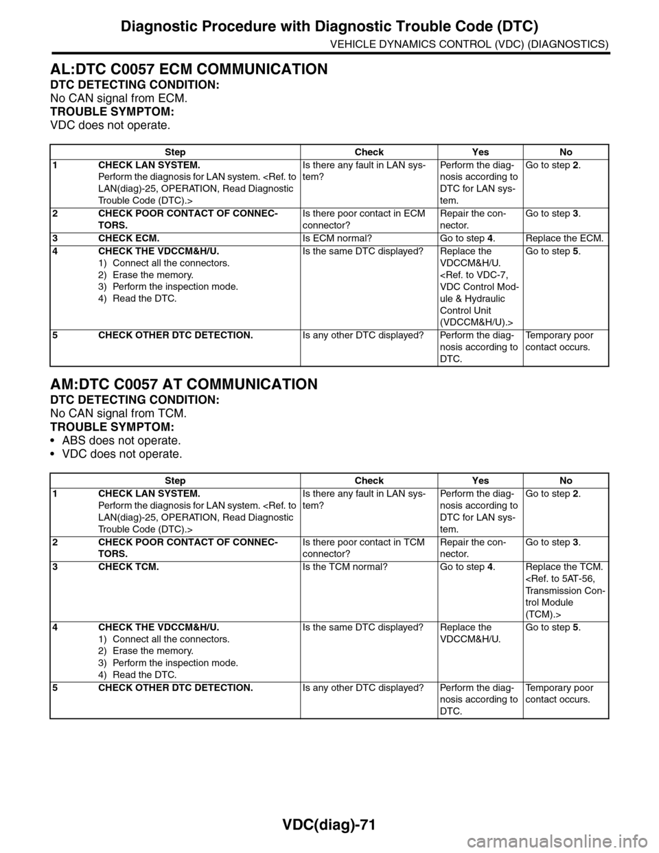
VDC(diag)-71
Diagnostic Procedure with Diagnostic Trouble Code (DTC)
VEHICLE DYNAMICS CONTROL (VDC) (DIAGNOSTICS)
AL:DTC C0057 ECM COMMUNICATION
DTC DETECTING CONDITION:
No CAN signal from ECM.
TROUBLE SYMPTOM:
VDC does not operate.
AM:DTC C0057 AT COMMUNICATION
DTC DETECTING CONDITION:
No CAN signal from TCM.
TROUBLE SYMPTOM:
•ABS does not operate.
•VDC does not operate.
Step Check Yes No
1CHECK LAN SYSTEM.
Perfor m the diagnosis for LAN system.
Tr o u b l e C o d e ( D T C ) . >
Is there any fault in LAN sys-
tem?
Pe r for m t h e d ia g -
nosis according to
DTC for LAN sys-
tem.
Go to step 2.
2CHECK POOR CONTACT OF CONNEC-
TORS.
Is there poor contact in ECM
connector?
Repair the con-
nector.
Go to step 3.
3CHECK ECM.Is ECM normal? Go to step 4.Replace the ECM.
4CHECK THE VDCCM&H/U.
1) Connect all the connectors.
2) Erase the memory.
3) Perform the inspection mode.
4) Read the DTC.
Is the same DTC displayed? Replace the
VDCCM&H/U.
ule & Hydraulic
Control Unit
(VDCCM&H/U).>
Go to step 5.
5CHECK OTHER DTC DETECTION.Is any other DTC displayed? Perform the diag-
nosis according to
DTC.
Te m p o r a r y p o o r
contact occurs.
Step Check Yes No
1CHECK LAN SYSTEM.
Perfor m the diagnosis for LAN system.
Tr o u b l e C o d e ( D T C ) . >
Is there any fault in LAN sys-
tem?
Pe r for m t h e d ia g -
nosis according to
DTC for LAN sys-
tem.
Go to step 2.
2CHECK POOR CONTACT OF CONNEC-
TORS.
Is there poor contact in TCM
connector?
Repair the con-
nector.
Go to step 3.
3CHECK TCM.Is the TCM normal? Go to step 4.Replace the TCM.
trol Module
(TCM).>
4CHECK THE VDCCM&H/U.
1) Connect all the connectors.
2) Erase the memory.
3) Perform the inspection mode.
4) Read the DTC.
Is the same DTC displayed? Replace the
VDCCM&H/U.
Go to step 5.
5CHECK OTHER DTC DETECTION.Is any other DTC displayed? Perform the diag-
nosis according to
DTC.
Te m p o r a r y p o o r
contact occurs.