Page 17 of 138
 Shift the selector lever to neutral.
Start the engine.
Wait 10 seconds without chan")
21B-17
MR-413-X44-21B000$236.mif
V2
Vdiag No: 04SEQUENTIAL GEARBOX
Fault finding - Replacement of components21B
G) Shift the selector lever to neutral.
Start the engine.
Wait 10 seconds without changing gear (to program the clutch biting point).
Check that the programming has been successful by referring to the following statuses:
–ET062 “Biting point programming” displays “DONE”,
–ET063 “Solenoid valve zero point programming” displays “DONE”.
If “NOT DONE”, repeat procedure E.
H) Check that PR145 "Engine coolant temperature" is above 80 ˚C and that PR095 "Clutch temperature" is
less than 180 ˚C.
Repeat starting at half-load 4 or 5 times to program the clutch progressivity.
Exit fault finding mode and switch off the ignition.
Wait 1 minute and then re-establish dialogue with the computer.
Check that programming has been successfully completed by referring to the following status:
–ET065 “Progressivity programming” displays “DONE”.
Repeat procedure F if status ET065 “Progressivity programming” displays “NOT DONE”.
I) Exit fault finding mode and switch off ignition.
Page 18 of 138
 Switch on the ignition.
B) Apply the following command:
–RZ001 S")
21B-18
MR-413-X44-21B000$236.mif
V2
Vdiag No: 04SEQUENTIAL GEARBOX
Fault finding - Replacement of components21B
HIGH PRESSURE PIPE
A) Switch on the ignition.
B) Apply the following command:
–RZ001 Stored faults.
Exit fault finding mode and switch off the ignition.
Wait 1 minute and then re-establish dialogue with the computer.
C) Rehabilitate the hydraulic unit using command AC007 "Hydraulic unit pump rehabilitation".
Open the bleed screw,
Gearbox in neutral position, handbrake engaged, engine speed zero and no fault with the solenoid valves and
the master slave sensors.
Bleed the clutch hydraulic circuit using command AC008 "Clutch circuit phase 1 bleed".
Close the bleed screw as soon as the fluid begins to run clear of air bubbles.
Wait for the procedure to end (this should take 6 minutes).
D) Bleed the clutch hydraulic circuit using command AC009 "Clutch circuit phase 2 bleed".
Wait for the procedure to end (this should take 8 minutes).
E) Exit fault finding mode and switch off the ignition. WARNING
For all operations carried out on the hydraulic unit, run commands AC006 Disable hydraulic unit pump
and AC081 Discharge pressure accumulator.
Use command AC081 until hydraulic pressure is close to zero.
Page 19 of 138
 Switch on the ignition.
B) Clear all programming using com")
21B-19
MR-413-X44-21B000$236.mif
V2
Vdiag No: 04SEQUENTIAL GEARBOX
Fault finding - Replacement of components21B
CLUTCH OR GEARBOX + CLUTCH
A) Switch on the ignition.
B) Clear all programming using commands
–RZ002 Programming,
–RZ003 Program biting point,
–RZ008 Initial closed position of clutch.
Exit fault finding mode and switch off the ignition.
Wait 1 minute and then re-establish dialogue with the computer.
C) Rehabilitate the hydraulic unit using command AC007 "Hydraulic unit pump rehabilitation".
Bleed the hydraulic circuit.
Open the bleed screw,
Start the engine with the handbrake applied.
Gearbox in neutral and no faults in the solenoid valves or master slave sensors.
Bleed the hydraulic circuit using command AC025 Bleed slave cylinder hydraulic circuit.
Repeat procedure C if not done.
D) Check that PR145 "Engine coolant temperature" is below 50 ˚C.
Program the gears with command VP008 Program selection/engagement ranges.
Wait for the procedure to end.
Exit fault finding mode and switch off the ignition.
Wait 1 minute and then re-establish dialogue with the computer.
Check that programming has been successful by referring to the following status:
–ET061 “Gear programming” displays “DONE”.
Brake and select all the gears in the gearbox, while checking that they are recognised on the display.
Repeat procedure D if not done.
E) Shift the selector lever to neutral.
Start the engine.
Wait 10 seconds without changing gear (to program the clutch biting point).
Repeat the clutch biting point programming 4 or 5 times.
Check that programming has been successful by referring to the following status:
–ET062 “Biting point programming” displays “DONE”.
If “NOT DONE”, repeat procedure E. WARNING
For all operations on the hydraulic circuit, activate commands AC006 "Hydraulic unit pump inhibition"
and AC081 "Discharge pressure accumulator" until the hydraulic pressure PR018 “Hydraulic pressure” is
close to zero.
Page 20 of 138
21B-20
MR-413-X44-21B000$236.mif
V2
Vdiag No: 04SEQUENTIAL GEARBOX
Fault finding - Replacement of components21B
I) Check that PR145 "Engine coolant temperature" is above 80 ˚C and that PR095 "Clutch temperature" is
less than 180 ˚C.
Repeat starting at half-load 4 or 5 times to program the clutch progressivity.
Exit fault finding mode and switch off the ignition.
Wait 1 minute and then re-establish dialogue with the computer.
Check that programming has been successfully completed by referring to the following status:
–ET065 “Progressivity programming” displays “DONE”.
Repeat procedure J if not done.
G) Exit fault finding mode and switch off ignition.
Page 21 of 138

21B-21
MR-413-X44-21B000$295.mif
V2
21B
SEQUENTIAL GEARBOX
Fault finding - Configurations and programming
SETTINGS
VP001: "Write VIN"
This command permits manual entry of the vehicle's VIN into the computer.
Use this command each time the computer is replaced or (re)programmed.
VP008: "Selection/engagement zones programming"
This command enables the gears to be programmed.
Use this command when:
–replacing the electrohydraulic unit, the clutch or the gearbox,
–replacing or reprogramming the computer,
–replacing the engagement position sensor and the selecting position sensor,
–replacing the engagement, selection or clutch solenoid valves.
–replacing the reservoir, accumulator or pump only.
VP009: "Enter last After-Sales operation date"
Use this command for each workshop operation on the sequential gearbox.
Select command VP009 on the diagnostic tool.
Enter the operation date with the tool keyboard.
VP013: "Enter new clutch fitting date"
This command should be used when the clutch is replaced.
Select command VP013 on the diagnostic tool.
Enter the operation date with the tool keyboard.
VP014: "Enter clutch initial closed position"
This command enables the value of the initial closed position of the clutch to be re-entered into a new or
reprogrammed computer in order to keep a consistent record of the clutch wear,.
Use this command each time the computer is replaced or reprogrammed. Note:
When replacing or reprogramming a computer, use command AC007 Hydraulic unit pump rehabilitation
before carrying out parameter VP008 Program selection/engagement ranges.
Vdiag No: 04
MR-413-X44-21B000$295.mif
Page 22 of 138

21B-22
MR-413-X44-21B000$354.mif
V2
21B
SEQUENTIAL GEARBOX
Fault finding - Fault summary table
*RR: rearTool faultAssociated
DTCDiagnostic tool title
DF0020613 Computer
DF0390725 Engine speed signal
DF0430785 Gear change consistency
DF0465002 Idling setpoint multiplex signal
DF0480720 Vehicle speed signal
DF059C100 Injection connection → Automatic transmission (multiplex line signal)
DF062C073 Multiplex line fault
DF0650945 Pump relay circuit
DF0670820 Lever position switch circuit
DF0680805 Clutch position sensor circuit
DF0690904 Selection position sensor circuit
DF0700914 Engagement position sensor circuit
DF0710750 Clutch solenoid valve circuit
DF0720755 Engagement solenoid valve 1 circuit
DF0730760 Engagement solenoid valve 2 circuit
DF0740765 Selection solenoid valve 1 circuit
DF0750770 Selection solenoid valve 2 circuit
DF0760900 Clutch control
DF0770928 Gearbox servo control
DF0780944 Hydraulic servo control
DF0800560 Battery voltage
DF0820571 Brake lights switch circuit
DF1075000 Engine speed multiplex signal
DF1084073 Effective average torque multiplex signal
DF1145007 Pedal position multiplex signal
DF1155005 Torque multiplex signal
DF1174037 RR* wheel speed multiplex signal left
DF118403A RR* right-hand wheel speed multiplex signal
DF122C140 Passenger compartment computer connection
Vdiag No: 04
MR-413-X44-21B000$354.mif
Page 23 of 138

21B-23
MR-413-X44-21B000$354.mif
V2
Vdiag No: 04SEQUENTIAL GEARBOX
Fault finding - Fault summary table21B
*signal: signal
* FR: frontTool faultAssociated
DTCDiagnostic tool title
DF1445001 Coolant temperature multiplex signal
DF1455003 Invalid pedal position multiplex signal*
DF1464074 Torque no reduction multiplex signal
DF1475004 Invalid anticipated torque multiplex signal*
DF1484040 Invalid switch 2 multiplex signal
DF150C155 Instrument panel multiplex connection
DF1660932 Pressure sensor circuit
DF1754031 FR* wheel speed multiplex signal left
DF1764034 FR* wheel speed multiplex signal right
DF1800942 Hydraulic pump
DF1810919 Gear selection impossible
DF185C121 No ABS/ESP multiplex signal
DF1870949 Programming
DF1880701 System operation
DF2320604 Computer
DF2330605 Computer
DF2340603 Computer
DF2510715 Gearbox input speed
DF2520946 Pump relay
DF2540218 Clutch temperature
DF2562711 Erratic gear jumping
DF2570934 Slow loss of hydraulic pressure
DF2580935 Rapid loss of hydraulic pressure
DF2590867 Pressure accumulator
DF2620780 Auto-adaptive pattern
DF2635006 Instantaneous maximum torque multiplex signal
DF2650885 Computer
Page 24 of 138

21B-24
MR-413-X44-21B000$413.mif
V2
21B
SEQUENTIAL GEARBOX
Fault finding - Interpretation of faults
DF002
PRESENT
OR
STOREDCOMPUTER
1.DEF: Internal electronic fault
NOTESSpecial note:
–fault warning light comes on.
Use the Wiring Diagrams Technical Note for New TWINGO.
Check the condition and positioning of the following fuses:
●Fuse F1 (30A) located in the engine fuse and relay box.
●Fuses F16 (20A) and F4 (7.5A) located in the passenger compartment fuse box.
Check the connection and condition of the 52-track connector of component 119.
If the connector is faulty and there is a repair procedure (see Technical Note 6015A, Electrical wiring repair,
Wiring: Precautions for repair), repair the connector, otherwise replace the wiring.
Check for + before ignition on connection BP39 and for + after ignition feed on connection AP4 on the
connector of component 119.
If the connection(s) are faulty and there is a repair method (see Technical Note 6015A, Repairing electrical
wiring, W iring: Precautions for repair), repair the wiring, otherwise replace it.
Check the insulation, continuity and the absence of interference resistance on the following connections:
●Connection code N between component 119 and the chassis earth MC - 12A.
●Connection code N between component 119 and the chassis earth MC - 12B.
If the connection(s) are faulty and there is a repair method (see Technical Note 6015A, Repairing electrical
wiring, W iring: Precautions for repair), repair the wiring, otherwise replace it.
Clear the computer fault memory and exit fault finding.
Switch off the ignition.
Switch on the ignition again and carry out a new check using the diagnostic tool.
If the fault is still present, contact the Techline.
AFTER REPAIRDeal with any faults displayed by the diagnostic tool.
Clear the computer memory.
Carry out a road test followed by another check with the diagnostic tool.
BVRJH1_V04_DF002
MR-413-X44-21B000$413.mif
Vdiag No.: 04
 1
1 2
2 3
3 4
4 5
5 6
6 7
7 8
8 9
9 10
10 11
11 12
12 13
13 14
14 15
15 16
16 17
17 18
18 19
19 20
20 21
21 22
22 23
23 24
24 25
25 26
26 27
27 28
28 29
29 30
30 31
31 32
32 33
33 34
34 35
35 36
36 37
37 38
38 39
39 40
40 41
41 42
42 43
43 44
44 45
45 46
46 47
47 48
48 49
49 50
50 51
51 52
52 53
53 54
54 55
55 56
56 57
57 58
58 59
59 60
60 61
61 62
62 63
63 64
64 65
65 66
66 67
67 68
68 69
69 70
70 71
71 72
72 73
73 74
74 75
75 76
76 77
77 78
78 79
79 80
80 81
81 82
82 83
83 84
84 85
85 86
86 87
87 88
88 89
89 90
90 91
91 92
92 93
93 94
94 95
95 96
96 97
97 98
98 99
99 100
100 101
101 102
102 103
103 104
104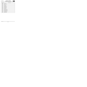 105
105 106
106 107
107 108
108 109
109 110
110 111
111 112
112 113
113 114
114 115
115 116
116 117
117 118
118 119
119 120
120 121
121 122
122 123
123 124
124 125
125 126
126 127
127 128
128 129
129 130
130 131
131 132
132 133
133 134
134 135
135 136
136 137
137 Check that PR145 \"Engine coolant temperature\" is above 80 ˚C and that PR095 \"Clutch")