Page 17 of 46
 F0
The assembly is held together by the tension created in
the bolt when it is tightened.
A reli")
01D-4
MECHANICAL INTRODUCTION
Tightening torques: General information
01D
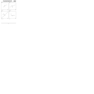
Creating tension (or preload) F0
The assembly is held together by the tension created in
the bolt when it is tightened.
A reliable assembly is only possible if the correct ten-
sion is used:
-insufficient tension: risk of loosening,
-too much tension: risk of deformation of the parts to
be assembled, or shearing of the bolt.Customer complaints resulting from incorrect tighten-
ing may be, following assembly, a safety issue (fire,
loss of control of the vehicle etc.), an immobilising fault
or a noise.
III - TIGHTENING PROCEDURES
The two controlled tightening procedures adapted to
automotive repairs because of their low cost and sim-
ple operation are torque tightening and angle tighten-
ing (also called torque and angle).
1 - Torque tightening
This is the most commonly used procedure. Is consists
of tightening until a given resisting torque is reached,
known as tightening torque.
The tightening torque is distributed in a large part as
friction torque (under the head and in the thread) and in
a small part as useful torque (to create the tension).
This practise spreads the tension significantly due to
the variation in the friction coefficients from one assem-
bly to another and the uncertainty of the tightening pro-
cedures and methods.
2 - Angle tightening
The principle consists of putting the parts of the assem-
bly in contact using a mating torque (approximately 25
to 30% of the final torque) then to tighten to a deter-
mined angle.
This method, which is not dependent on the friction of
the tightened assembly, gives more precise results
than torque tightening.
IV - OBSERVING THE TIGHTENING TORQUES AND
ANGLES
Bolted assemblies whose tightening torques and an-
gles are explicitly specified in the removal / refitting
procedures must be observed using the appropriate
tools (torque wrench, angle measuring disc). Failure to
observe this can lead to safety risks, immobilising
faults or unwanted noises.
For other bolted assemblies, non-measured tightening
(using standard spanners) is acceptable. Neverthe-
less, the corresponding tightening torque is indicated in
the table of standard tightening torques.
V - RECOMMENDED TIGHTENING TOOLS
For measured tightening, the repairer must have avail-
able torque wrenches to tighten from 4 to 400 N.m as
well as an angle measuring disc.
The torque wrenches used may be click type or elec-
tronic.
120738
120739
(3) Bolt
(4) Assembled components
(5) Extension of the bolt
(6) Non-tightened assembly
(7) Tightened assembly
(X1) compression of the assembly
(Fo) tension
(C) tightening torque
Page 18 of 46

01D-5
MECHANICAL INTRODUCTION
Tightening torques: General information
01D
For example:
-1 torque wrench 4 - 40 N.m,
-1 torque wrench 20 - 100 N.m,
-1 torque wrench 80 - 400 N.m,
-1 angle measurement disc.
The torque wrenches used must comply with the ISO
6789 standard. They must be calibrated regularly fol-
lowing the supplier's recommendations using the ap-
propriate procedures.
VI - PRECAUTIONS WHEN USING A CLICK TYPE
TORQUE WRENCH
A click type torque wrench is a manual tightening tool.
The trigger mechanism causes a break or disengage-
ment of the wrench past a force threshold.
This threshold depends on the setting of the wrench
but also depends on the way the wrench is handled.
When used following best practises, the accuracy of
the tightness when using a click type torque wrench is
± 15%.
The instructions to be observed are:
- Place the hand in the centre of the handle. An incor-
rectly positioned hand on the handle will alter the trig-
ger threshold.- Pull the wrench gently and steadily, without applying
any torsion. Excessive tightening speed as well as jerk-
iness are major causes of overtightening. Any torsion
applied to the wrench will alter the trigger threshold.
- Hold the wrench on the bolt using a minimum of effort.
Any effort applied to the wrench head will alter the trig-
ger threshold.
- Apply the tightening effort perpendicular to the mount-
ing observing a tolerance of ± 15˚ relative to the per-
pendicularity. If the wrench is not perpendicular to the
mounting axis, this will result in insufficient tightening.
- Stop tightening as soon as the wrench is triggered.
Continued tightening after the wrench is triggered will
lead to overtightening.
120740
(6) lever arm
120741
120742
Page 19 of 46
 it is essential to recali-
brate the wre")
01D-6
MECHANICAL INTRODUCTION
Tightening torques: General information
01D
If the length of the wrench is modified (extending the
handle, adapting an end piece) it is essential to recali-
brate the wrench to its new configuration.
Modifying the length of the wrench will modify its trigger
threshold.
Use the formula: C1 = CO x L2 / (L1+L2)
-CO: torque to apply,
-C1: adjustment torque to be displayed on the wrench,
-L1: length of the extension,
-L2: length of the wrench.
Unless there are special instructions in the repair meth-
od, a universal joint (CARDAN joint type) should be
used for measured tightening. Using a universal joint
will result in a difference between the set torque of the
wrench and the actual torque applied.
Before storing the wrench, loosen the adjustment
spring completely. A wrench stored with a spring under
tension will lose its tightening accuracy.
VII - PRECAUTIONS WHEN USING ELECTRONIC
TORQUE WRENCHES
An electronic torque wrench is a manual tightening
tool. The tightening torque and, depending on the mod-
el, the angle is read directly.
When used following best practises, the accuracy of
the tightness when using an electronic torque wrench
is ± 5%.
Electronic torque wrenches are not affected by the po-
sition of the operator's hand.It is advisable to handle the wrench with care and to
stop tightening when the required value is displayed on
the wrench.
120743
Page 20 of 46

02A-1
LIFTING EQUIPMENT
Vehicle: Towing and lifting
02A
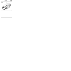
I - TOWING1 - Position of front attachment point
2 - Position of rear attachment point
II - LIFTING BY TROLLEY JACK Equipment required
Diagnostic tool
safety strap(s)
WARNING
See the current towing regulations in each country.
Never use the drive shafts as attachment points.
The towing points may only be used for towing on
the road.
Never use the towing points for removing the vehi-
cle from a ditch or to lift the vehicle, either directly
or indirectly.
Screw in and lock the towing ring before towing.
Vehicles fitted with automatic transmission:
-The vehicle should preferably be transported on a
platform or towed by lifting the front wheels. As an
exception, the vehicle may be towed with the
wheels on the ground but at a speed below 12
mph (20km/h) and over a maximum distance of
18 miles (30 kms) (with the gear lever in neutral).
Vehicles fitted with Renault Card:
-If the vehicle battery is flat, the steering column
remains locked. In this case, fit a new battery or
connect to an electrical source to lock the airbag
computer using the Diagnostic tool (see Airbag
and pretensioners: Precautions for the repair)
(88C, Airbag and pretensioners), which unlocks
the steering column.
-If it is not possible to lock the airbag computer, the
front of the vehicle must be lifted.
120735
120450
IMPORTANT
To prevent any accidents, the trolley jack must only
be used to lift and/or move the vehicle. The vehicle
height must be maintained with axle stands which
are strong enough to support the weight of the vehi-
cle.
Page 21 of 46
02A-2
LIFTING EQUIPMENT
Vehicle: Towing and lifting
02A
To mount the vehicle onto axle stands, lift the entire ve-
hicle on one side and the axle stands must be placed
under zones (1) and (2) designed for positioning the
tool kit jack.
III - LIFTING ON A LIFT
1 - Safety advice reminder
To remove heavy components from the vehicle (engine
and transmission assembly, rear axle, gearbox), use a
four-post lift.
If the vehicle is on a two-post lift, there is a danger that
it will tip after removal of these types of components.
Fit the safety strap(s) available from Spare Parts De-
partment. WARNING
To avoid any damage to the original protection, use
equipment fitted with rubber pads to prevent the
equipment coming into direct contact with the vehi-
cle.
To avoid any damage to the axle assemblies, the
vehicle must not be raised using the front suspen-
sion arms for suppor t or under the rear axle.
120614
120616
14894
Page 22 of 46

02A-3
LIFTING EQUIPMENT
Vehicle: Towing and lifting
02A
2 - Fitting the straps
For safety reasons, these straps must always be in
perfect condition. Replace them as soon as they show
signs of wear.
When fitting the straps, check that the seats and fragile
parts of the vehicle are correctly protected.
If there is a danger of the vehicle tipping forward:
-place the strap under the rear right-hand arm of the
lift,
-pass the strap through the inside of the vehicle,
-pass the strap under the left-hand rear arm of the lift,
-pass the strap through the inside of the vehicle again,
-tighten the strap.
If there is a danger of the vehicle tipping bac-
kwards:
-place the strap under the front right-hand arm of the
lift,
-pass the strap through the inside of the vehicle,
-pass the strap under the front left-hand arm of the lift,
-pass the strap through the inside of the vehicle again,
-tighten the strap.3 - Permitted jacking points
Front lifting points
Rear lifting points
120612
120613
120615
IMPORTANT
Only the jacking points described in this section
allow the vehicle to be raised in complete safety.
Do not raise the vehicle using points other than
those described in this section.
Page 23 of 46
02A-4
LIFTING EQUIPMENT
Vehicle: Towing and lifting
02A
To raise the vehicle, position the lifting arm pads as
shown above, taking care not to damage the end of the
front wing and the underside of the sill panel.
Page 24 of 46
03B-1
COLLISION
Vehicle involved in an impact: Impact fault finding
03B
SUB-FRAME INSPECTION
a
1 - Chronological order of checks:
aFRONT impact
-1: (B) - (Ad) = (Bd) - (A)
-2: (B) - (Gd) = (Bd) - (G)
aREAR impact
-1: (A) - (Bd) = (Ad) - (B)
-2: (G) - (Bd) = (Gd) - (B)
121744


 and (2) designed")

 - (Ad) = (Bd) - (A)
-2: (B) - (Gd) = (Bd) - (G")