Page 65 of 269

13B-65
AFTER REPAIRDeal with any faults displayed by the diagnostic tool.
Clear the computer fault memory.
Carry out a road test followed by another check with the diagnostic tool.
V6 MR-413-X44-13B000$100.mif
DIESEL INJECTION
Fault finding – Interpretation of faults13B
DCM 1.2 Injection
Program No.: 4D
Vdiag No.: 48, 4C, 50,
54, 58, 5C
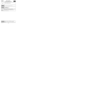
DF029
CONTINUED 1
YESInjector 4 is not defective; the fault is in the injector 4 control circuit.
Check the insulation and continuity of the following connections:
–3LC between components 196 and 120,
–3KZ between components 196 and 120.
If the connection or connections are faulty and there is a repair procedure
(see Technical Note 6015A, Electrical wiring repair, Wiring: Precautions
for repair), repair the wiring, otherwise replace the wiring.
If the fault is still present, contact the Techline.
NOInjector 4 is faulty, replace the cylinder 3 injector, component code 195 (see MR 364
(Mégane II), MR 370 (Scénic II), MR 385 (Modus), MR 392 (Clio III), MR 411
(New Twingo), MR 417 (Kangoo 2), Mechanical, 13B, Diesel injection, Diesel
injector: Removal - Refitting).
Page 66 of 269

13B-66
AFTER REPAIRDeal with any faults displayed by the diagnostic tool.
Clear the computer fault memory.
Carry out a road test followed by another check with the diagnostic tool.
V6 MR-413-X44-13B000$100.mif
DIESEL INJECTION
Fault finding – Interpretation of faults13B
DCM 1.2 Injection
Program No.: 4D
Vdiag No.: 48, 4C, 50,
54, 58, 5C
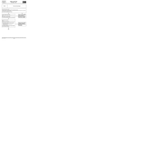
* C2I: Individual injector correction
DF029
CONTINUED 2
1.DEF
2.DEFNOTESNone.
Check the conformity of the injectors fitted to the vehicle in relation to the type of vehicle and engine number (low,
high or very high pressure injector).
Check that the C2I* is entered correctly in the injection computer.
Check the accelerometer shielding on connection TB1 of component 120.
Check that the accelerometer is secured on the engine.
After retightening the accelerometer, be sure to clear the pressure regulation adaptives using command
RZ004 Pressure regulation adaptives.
Carry out a road test to check if the fault is still present.
If the fault is still present, replace the cylinder 4 injector, component code 196 (see MR 364 (Mégane II), MR 370
(Scénic II), MR 385 (Modus), MR 392 (Clio III), MR 411 (New Twingo), MR 417 (Kangoo 2), Mechanical, 13B,
Diesel injection, Diesel injector: Removal - Refitting).
Page 67 of 269

13B-67
AFTER REPAIRDeal with any faults displayed by the diagnostic tool.
Clear the computer fault memory.
Carry out a road test followed by another check with the diagnostic tool.
V6 MR-413-X44-13B000$100.mif
DIESEL INJECTION
Fault finding – Interpretation of faults13B
DCM 1.2 Injection
Program No.: 4D
Vdiag No.: 50, 58
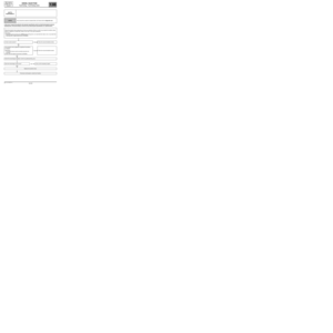
DF032
PRESENT
OR
STOREDTHERMOPLUNGER 1 RELAY CONTROL CIRCUIT
NOTESConditions for applying the fault finding procedure to stored faults:
The fault is present when the ignition is switched on.
See the Technical Note Wiring Diagrams for the vehicle.
For New Twingo
Check the connection and condition of the additional heater 1 relay connector, component code 1067 and the 80 A
maxi fuse in the engine fuse and relay box.
Check the connection and condition of the injection computer connector, component code 120.
If the connector(s) is faulty and if there is a repair procedure (see Technical Note 6015A, Repairing electrical
wiring, Wiring: Precautions for repair), repair the connector, otherwise replace the wiring.
Run command AC250 Heating resistor 1 relay.
If the command does not run, check, with the ignition on, for earth on connection 3JA of component 1067.
Check for + 12 V on connection 3FB of component 1067.
If the connection or connections are faulty and there is a repair procedure (see Technical Note 6015A, Electrical
wiring repair, Wiring: Precautions for repair), repair the wiring, otherwise replace the wiring.
Check the insulation and continuity of the following connections:
–3JA between components 1067 and 120,
–3FB between components 1067 and 238,
–38LL between components 1067 and 1113,
–BP9 between components 1067 and 597.
If the connection or connections are faulty and there is a repair procedure (see Technical Note 6015A, Electrical
wiring repair, Wiring: Precautions for repair), repair the wiring, otherwise replace the wiring.
If the fault is still present, check the relay and replace it if necessary.
If the fault is still present, contact the Techline.
DCM1.2_V50_DF032/DCM1.2_V58_DF032
Page 68 of 269

13B-68
AFTER REPAIRDeal with any faults displayed by the diagnostic tool.
Clear the computer fault memory.
Carry out a road test followed by another check with the diagnostic tool.
V6 MR-413-X44-13B000$100.mif
DIESEL INJECTION
Fault finding – Interpretation of faults13B
DCM 1.2 Injection
Program No.: 4D
Vdiag No.: 50, 58
DF032
CONTINUED
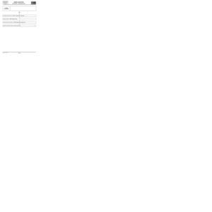
For Mégane II
and Scénic II:
Check the connection and condition of the connector of the additional heater interface unit, component code 1550
and the 70 A maxi fuses on the power supply fuse board.
Check the connection and condition of the injection computer connector, component code 120.
If the connector(s) is faulty and if there is a repair procedure (see Technical Note 6015A, Repairing electrical
wiring, Wiring: Precautions for repair), repair the connector, otherwise replace the wiring.
Run command AC250 Heating resistor 1 relay.
If the command does not run, check for + 12 V on connections BP27 and BP35 of component 1550.
If the connection or connections are faulty and there is a repair procedure (see Technical Note 6015A, Electrical
wiring repair, Wiring: Precautions for repair), repair the wiring, otherwise replace the wiring.
Check the insulation and continuity of the following connections:
–3JA between components 1550 and 120,
–3JAA between components 1550 and 120,
–3JAB between components 1550 and 120.
If the connection or connections are faulty and there is a repair procedure (see Technical Note 6015A, Electrical
wiring repair, Wiring: Precautions for repair), repair the wiring, otherwise replace the wiring.
If the fault is still present, check the relay and replace it if necessary.
If the fault is still present, contact the Techline.
Page 69 of 269

13B-69
AFTER REPAIRDeal with any faults displayed by the diagnostic tool.
Clear the computer fault memory.
Carry out a road test followed by another check with the diagnostic tool.
V6 MR-413-X44-13B000$100.mif
DIESEL INJECTION
Fault finding – Interpretation of faults13B
DCM 1.2 Injection
Program No.: 4D
Vdiag No.: 50, 58
DF033
PRESENT
OR
STOREDTHERMOPLUNGER 2 RELAY CONTROL CIRCUIT
NOTESConditions for applying the fault finding procedure to stored faults:
The fault is present when the ignition is switched on.
See the Technical Note Wiring Diagrams for the vehicle.
Check the connection and condition of the additional heater 2 relay connector, component code 1068
and the 80 A maxi fuse in the engine fuse and relay box.
Check the connection and condition of the injection computer connector, component code 120.
If the connector(s) are faulty and if there is a repair procedure (see Technical Note 6015A, Repairing electrical
wiring, Wiring: Precautions for repair), repair the connector, otherwise replace the wiring.
Run command AC251 Heating resistor 2 relay.
If the command does not run, check, with the ignition on, for earth on connection 3JAA of component 1068.
Check for + 12 V on connection 3FB of component 1068.
If the connector is faulty and if there is a repair procedure (see Technical Note 6015A, Repairing electrical
wiring, Wiring: Precautions for repair), repair the connector, otherwise replace the wiring.
Check the insulation and continuity of the following connections:
–3JAA between components 1068 and 120,
–3FB between components 1068 and 238,
–38LM between components 1068 and 1113,
–BP9 between components 1068 and 597.
If the connection or connections are faulty and there is a repair procedure (see Technical Note 6015A, Electrical
wiring repair, Wiring: Precautions for repair), repair the wiring, otherwise replace the wiring.
If the fault is still present, check the relay and replace it if necessary.
If the fault is still present, contact the Techline.
DCM1.2_V50_DF033/DCM1.2_V58_DF033
Page 70 of 269

13B-70
AFTER REPAIRDeal with any faults displayed by the diagnostic tool.
Clear the computer fault memory.
Carry out a road test followed by another check with the diagnostic tool.
V6 MR-413-X44-13B000$100.mif
DIESEL INJECTION
Fault finding – Interpretation of faults13B
DCM 1.2 Injection
Program No.: 4D
Vdiag No.: 50, 58
DF034
PRESENT
OR
STOREDTHERMOPLUNGER 3 RELAY CONTROL CIRCUIT
NOTESConditions for applying the fault finding procedure to stored faults:
The fault is present when the ignition is switched on.
See the Technical Note Wiring Diagrams for the vehicle.
Check the connection and condition of the additional heater 2 relay connector, component code 1068
and the 80 A maxi fuse in the engine fuse and relay box.
Check the connection and condition of the injection computer connector, component code 120.
If the connector(s) are faulty and if there is a repair procedure (see Technical Note 6015A, Repairing electrical
wiring, Wiring: Precautions for repair), repair the connector, otherwise replace the wiring.
Run command AC251 Heating resistor 2 relay.
If the command does not run, check, with the ignition on, for earth on connection 3JAA of component 1068.
Check for + 12 V on connection 3FB of component 1068.
If the connector is faulty and if there is a repair procedure (see Technical Note 6015A, Repairing electrical
wiring, Wiring: Precautions for repair), repair the connector, otherwise replace the wiring.
Check the insulation and continuity of the following connections:
–3JAA between components 1068 and 120,
–3FB between components 1068 and 238,
–38LM between components 1068 and 1113,
–BP9 between components 1068 and 597.
If the connection or connections are faulty and there is a repair procedure (see Technical Note 6015A, Electrical
wiring repair, Wiring: Precautions for repair), repair the wiring, otherwise replace the wiring.
If the fault is still present, check the relay and replace it if necessary.
If the fault is still present, contact the Techline.
DCM1.2_V50_DF034/DCM1.2_V58_DF034
Page 71 of 269
13B-71
AFTER REPAIRDeal with any faults displayed by the diagnostic tool.
Clear the computer fault memory.
Carry out a road test followed by another check with the diagnostic tool.
V6 MR-413-X44-13B000$100.mif
DIESEL INJECTION
Fault finding – Interpretation of faults13B
DCM 1.2 Injection
Program No.: 4D
Vdiag No.: 48, 4C, 50,
54, 58, 5C
DF037
PRESENT
OR
STOREDENGINE IMMOBILISER
NOTESNone.
Run a multiplex network test (see 88B, Multiplex).
If the fault is still present, see 82A Engine immobiliser.
DCM1.2_V48_DF037/DCM1.2_V4C_DF037/DCM1.2_V50_DF037/DCM1.2_V54_DF037/DCM1.2_V58_DF037/DCM1.2_V5C_DF037
Page 72 of 269

13B-72
AFTER REPAIRDeal with any faults displayed by the diagnostic tool.
Clear the computer fault memory.
Carry out a road test followed by another check with the diagnostic tool.
V6 MR-413-X44-13B000$100.mif
DIESEL INJECTION
Fault finding – Interpretation of faults13B
DCM 1.2 Injection
Program No.: 4D
Vdiag No.: 48, 4C, 50,
54, 58, 5C
* C2I: Individual injector correction
DF038
PRESENT
OR
STOREDCOMPUTER1.DEF: Analogue - digital converter
2.DEF: Enter injector codes
3.DEF: Memory self-test
4.DEF: Watchdog not refreshed
5.DEF: Interference on the injector control line
6.DEF: Watchdog activation
NOTESSpecial notes:
When this fault appears:
either: the engine speed is locked at 1300 rpm, the engine is noisy, and the level 1
warning light illuminates with the message Check injection displayed on the
instrument panel,
or: the engine stops and the level 2 warning light illuminates with the message Faulty
injection displayed on the instrument panel.
See the Technical Note Wiring Diagrams for the vehicle.
1.DEF
3.DEF
4.DEF
6.DEF
NOTESNone.
Contact Techline.
2.DEF
NOTESNone.
Check that the individual injector correction (C2I*) matches the injectors; if not, enter the C2I*
(see Configurations and programming).
If the C2I* does match the injectors, contact the Techline.
DCM1.2_V48_DF038/DCM1.2_V4C_DF038/DCM1.2_V50_DF038/DCM1.2_V54_DF038/DCM1.2_V58_DF038/DCM1.2_V5C_DF038