2009 NISSAN TIIDA lock
[x] Cancel search: lockPage 1811 of 4331
![NISSAN TIIDA 2009 Service Repair Manual ON BOARD REFUELING VAPOR RECOVERY (ORVR)
EC-455
< COMPONENT DIAGNOSIS >
[HR16DE] C
D E
F
G H
I
J
K L
M A EC
NP
O
Is the inspection result normal? YES >> INSPECTION END
NO >> Replace refueling EVAP vap NISSAN TIIDA 2009 Service Repair Manual ON BOARD REFUELING VAPOR RECOVERY (ORVR)
EC-455
< COMPONENT DIAGNOSIS >
[HR16DE] C
D E
F
G H
I
J
K L
M A EC
NP
O
Is the inspection result normal? YES >> INSPECTION END
NO >> Replace refueling EVAP vap](/manual-img/5/57398/w960_57398-1810.png)
ON BOARD REFUELING VAPOR RECOVERY (ORVR)
EC-455
< COMPONENT DIAGNOSIS >
[HR16DE] C
D E
F
G H
I
J
K L
M A EC
NP
O
Is the inspection result normal? YES >> INSPECTION END
NO >> Replace refueling EVAP vapor cut valve with fuel tank.
Component Inspection (Drain filter) INFOID:00000000048065591.
CHECK DRAIN FILTER
1. Check visually for insect nests in the drain filter air inlet.
2. Check visually for cracks or flaws in the appearance.
3. Check visually for cracks or flaws in the hose.
4. Blow air into port A and check that it flows freely out of port B.
5. Block port B.
6. Blow air into port A and check that there is no leakage.
Is the inspection result normal? YES >> INSPECTION END
NO >> Replace drain filter. 1. Filler tube 2. Recirculation line 3. EVAP/ORVR line
4. Vacuum/pressure handy pump 5. Fuel tank BBIA0694E
PBIB3641E
Page 1833 of 4331

EC
NP
O
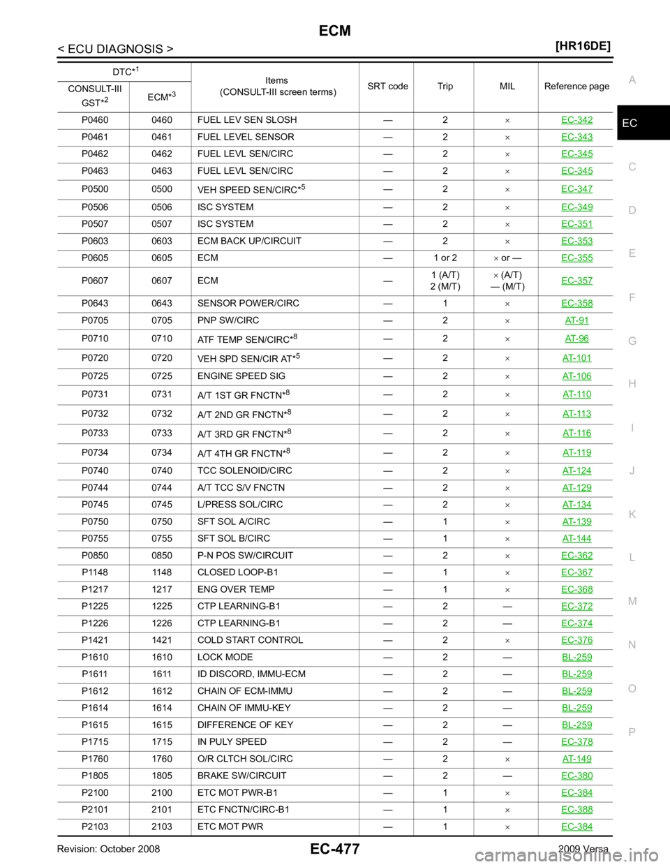
P0460 0460 FUEL LEV SEN SLOSH — 2
×EC-342 P0461 0461 FUEL LEVEL SENSOR — 2
×EC-343 P0462 0462 FUEL LEVL SEN/CIRC — 2
×EC-345 P0463 0463 FUEL LEVL SEN/CIRC — 2
×EC-345 P0500 0500
VEH SPEED SEN/CIRC*5
— 2 ×EC-347 P0506 0506 ISC SYSTEM — 2
×EC-349 P0507 0507 ISC SYSTEM — 2
×EC-351 P0603 0603 ECM BACK UP/CIRCUIT — 2
×EC-353 P0605 0605 ECM — 1 or 2
× or — EC-355 P0607 0607 ECM —
1 (A/T)
2 (M/T) ×
(A/T)
— (M/T) EC-357 P0643 0643 SENSOR POWER/CIRC — 1
×EC-358 P0705 0705 PNP SW/CIRC — 2
×AT-91 P0710 0710
ATF TEMP SEN/CIRC*8
— 2 ×AT-96 P0720 0720
VEH SPD SEN/CIR AT*5
— 2 ×AT-101 P0725 0725 ENGINE SPEED SIG — 2
×AT-106 P0731 0731
A/T 1ST GR FNCTN*8
— 2 ×AT-110 P0732 0732
A/T 2ND GR FNCTN*8
— 2 ×AT-113 P0733 0733
A/T 3RD GR FNCTN*8
— 2 ×AT-116 P0734 0734
A/T 4TH GR FNCTN*8
— 2 ×AT-119 P0740 0740 TCC SOLENOID/CIRC — 2
×AT-124 P0744 0744 A/T TCC S/V FNCTN — 2
×AT-129 P0745 0745 L/PRESS SOL/CIRC — 2
×AT-134 P0750 0750 SFT SOL A/CIRC — 1
×AT-139 P0755 0755 SFT SOL B/CIRC — 1
×AT-144 P0850 0850 P-N POS SW/CIRCUIT — 2
×EC-362 P1148 1148 CLOSED LOOP-B1 — 1
×EC-367 P1217 1217 ENG OVER TEMP — 1
×EC-368 P1225 1225 CTP LEARNING-B1 — 2 —
EC-372P1226 1226 CTP LEARNING-B1 — 2 —
EC-374P1421 1421 COLD START CONTROL — 2
×EC-376 P1610 1610 LOCK MODE — 2 —
BL-259P1611 1611 ID DISCORD, IMMU-ECM — 2 —
BL-259P1612 1612 CHAIN OF ECM-IMMU — 2 —
BL-259P1614 1614 CHAIN OF IMMU-KEY — 2 —
BL-259P1615 1615 DIFFERENCE OF KEY — 2 —
BL-259P1715 1715 IN PULY SPEED — 2 —
EC-378P1760 1760 O/R CLTCH SOL/CIRC — 2
×AT-149 P1805 1805 BRAKE SW/CIRCUIT — 2 —
EC-380P2100 2100 ETC MOT PWR-B1 — 1
×EC-384 P2101 2101 ETC FNCTN/CIRC-B1 — 1
×EC-388 P2103 2103 ETC MOT PWR — 1
×EC-384 DTC*
1
Items
(CONSULT-III screen terms) SRT code Trip MIL Reference page
CONSULT-III
GST* 2
ECM*3
Page 1845 of 4331

EC
NP
O
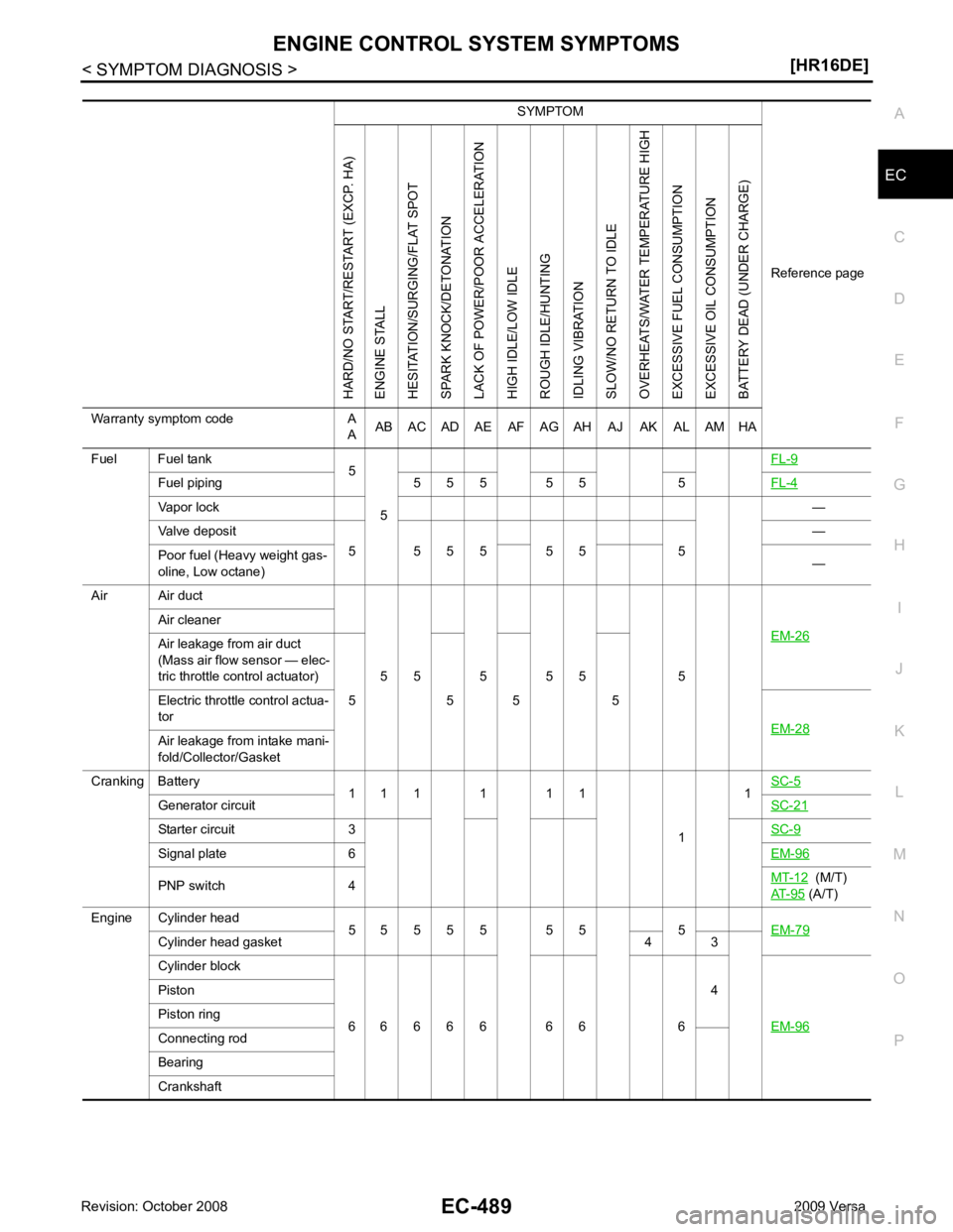
SYMPTOM
Reference pageHARD/NO START/RESTART (EXCP. HA)
ENGINE STALL
HESITATION/SURGING/FLAT SPOT
SPARK KNOCK/DETONATION
LACK OF POWER/POOR ACCELERATION
HIGH IDLE/LOW IDLE
ROUGH IDLE/HUNTING
IDLING VIBRATION
SLOW/NO RETURN TO IDLE
OVERHEATS/WATER TEMPERATURE HIGH
EXCESSIVE FUEL CONSUMPTION
EXCESSIVE OIL CONSUMPTION
BATTERY DEAD (UNDER CHARGE)
Warranty symptom code A AAB AC AD AE AF AG AH AJ AK AL AM HA
Fuel Fuel tank 5
5 FL-9Fuel piping 5 5 5 5 5 5
FL-4Vapor lock
—
Valve deposit 5 5 5 5 5 5 5 —
Poor fuel (Heavy weight gas-
oline, Low octane) —
Air Air duct
5 5 5 5 5 5 EM-26Air cleaner
Air leakage from air duct
(Mass air flow sensor — elec-
tric throttle control actuator)
5 5 5 5
Electric throttle control actua-
tor EM-28Air leakage from intake mani-
fold/Collector/Gasket
Cranking Battery 1 1 1 1 1 1
11
SC-5 Generator circuit
SC-21Starter circuit 3
SC-9Signal plate 6
EM-96PNP switch 4
MT-12 (M/T)
AT-95 (A/T)
Engine Cylinder head 5 5 5 5 5 5 5 5 EM-79Cylinder head gasket 4 3
Cylinder block
6 6 6 6 6 6 6 6 4
EM-96 Piston
Piston ring
Connecting rod
Bearing
Crankshaft
Page 1848 of 4331
![NISSAN TIIDA 2009 Service Repair Manual EC-492< PRECAUTION >
[HR16DE]
PRECAUTIONS
PRECAUTION
PRECAUTIONS
Precaution for Supplemental Restraint Syst em (SRS) "AIR BAG" and "SEAT BELT
PRE-TENSIONER" INFOID:0000000004786987
The Supplemental NISSAN TIIDA 2009 Service Repair Manual EC-492< PRECAUTION >
[HR16DE]
PRECAUTIONS
PRECAUTION
PRECAUTIONS
Precaution for Supplemental Restraint Syst em (SRS) "AIR BAG" and "SEAT BELT
PRE-TENSIONER" INFOID:0000000004786987
The Supplemental](/manual-img/5/57398/w960_57398-1847.png)
EC-492< PRECAUTION >
[HR16DE]
PRECAUTIONS
PRECAUTION
PRECAUTIONS
Precaution for Supplemental Restraint Syst em (SRS) "AIR BAG" and "SEAT BELT
PRE-TENSIONER" INFOID:0000000004786987
The Supplemental Restraint System such as “A IR BAG” and “SEAT BELT PRE-TENSIONER”, used along
with a front seat belt, helps to reduce the risk or severi ty of injury to the driver and front passenger for certain
types of collision. This system includes seat belt switch inputs and dual stage front air bag modules. The SRS
system uses the seat belt switches to determine the front air bag deployment, and may only deploy one front
air bag, depending on the severity of a collision and w hether the front occupants are belted or unbelted.
Information necessary to service the system safely is included in the “SUPPLEMENTAL RESTRAINT SYS-
TEM” and “SEAT BELTS” of this Service Manual.
WARNING:
• To avoid rendering the SRS inopera tive, which could increase the risk of personal injury or death in
the event of a collision which would result in air bag inflation, all maintenance must be performed by
an authorized NISS AN/INFINITI dealer.
• Improper maintenance, including in correct removal and installation of the SRS, can lead to personal
injury caused by unintent ional activation of the system. For re moval of Spiral Cable and Air Bag
Module, see the “SUPPLEMEN TAL RESTRAINT SYSTEM”.
• Do not use electrical test equipmen t on any circuit related to the SRS unless instructed to in this
Service Manual. SRS wiring harn esses can be identified by yellow and/or orange harnesses or har-
ness connectors.
PRECAUTIONS WHEN USING POWER TOOLS (AIR OR ELECTRIC) AND HAMMERS
WARNING:
• When working near the Airbag Diagnosis Sensor Unit or other Airbag System sensors with the igni-
tion ON or engine running, DO NOT use air or electri c power tools or strike near the sensor(s) with a
hammer. Heavy vibration could activate the sensor( s) and deploy the air bag(s), possibly causing
serious injury.
• When using air or electric power tools or hammers , always switch the ignition OFF, disconnect the
battery, and wait at least 3 minu tes before performing any service.
Precaution for Procedure without Cowl Top Cover INFOID:0000000004786988
When performing the procedure after removing cowl top cover, cover
the lower end of windshield with urethane, etc.
On Board Diagnosis (OBD) S ystem of Engine and A/T INFOID:0000000004780394
The ECM has an on board diagnostic system. It will light up the malfunction indicator lamp (MIL) to warn the
driver of a malfunction causing emission deterioration.
CAUTION:
• Be sure to turn the ignition sw itch OFF and disconnect the negative battery cable before any repair
or inspection work. The open/short circuit of re lated switches, sensors, solenoid valves, etc. will
cause the MIL to light up.
• Be sure to connect and lock the connectors secure ly after work. A loose (unlocked) connector will
cause the MIL to light up due to the open circuit. (Be sure the connector is free from water, grease,
dirt, bent terminals, etc.)
• Certain systems and components, especially those related to OBD, may use a new style slide-lock-
ing type harness connector. For descrip tion and how to disconnect, refer to PG-64, " Description " .PIIB3706J
Page 1859 of 4331

EC
NP
O
Inspection
INFOID:0000000004780402
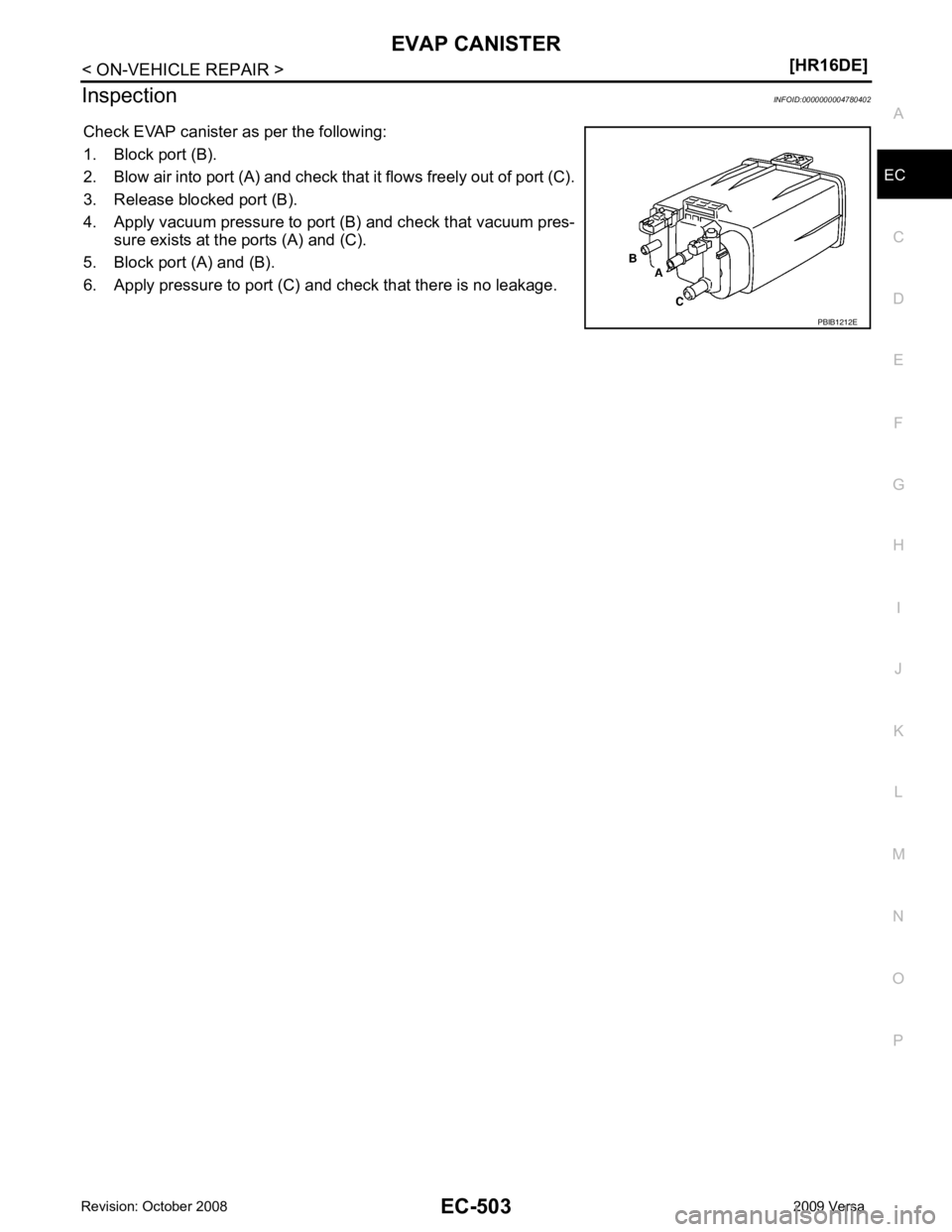
Check EVAP canister as per the following:
1. Block port (B).
2. Blow air into port (A) and check that it flows freely out of port (C).
3. Release blocked port (B).
4. Apply vacuum pressure to port (B) and check that vacuum pres-
sure exists at the ports (A) and (C).
5. Block port (A) and (B).
6. Apply pressure to port (C) and check that there is no leakage.
Page 1868 of 4331
![NISSAN TIIDA 2009 Service Repair Manual EC-512< SERVICE INFOMATION >
[MR TYPE 1]
PRECAUTIONS
PRECAUTIONS
Precaution for Supplemental Restraint Syst em (SRS) "AIR BAG" and "SEAT BELT
PRE-TENSIONER" INFOID:0000000004537013
The Supplemental NISSAN TIIDA 2009 Service Repair Manual EC-512< SERVICE INFOMATION >
[MR TYPE 1]
PRECAUTIONS
PRECAUTIONS
Precaution for Supplemental Restraint Syst em (SRS) "AIR BAG" and "SEAT BELT
PRE-TENSIONER" INFOID:0000000004537013
The Supplemental](/manual-img/5/57398/w960_57398-1867.png)
EC-512< SERVICE INFOMATION >
[MR TYPE 1]
PRECAUTIONS
PRECAUTIONS
Precaution for Supplemental Restraint Syst em (SRS) "AIR BAG" and "SEAT BELT
PRE-TENSIONER" INFOID:0000000004537013
The Supplemental Restraint System such as “A IR BAG” and “SEAT BELT PRE-TENSIONER”, used along
with a front seat belt, helps to reduce the risk or severi ty of injury to the driver and front passenger for certain
types of collision. This system includes seat belt switch inputs and dual stage front air bag modules. The SRS
system uses the seat belt switches to determine the front air bag deployment, and may only deploy one front
air bag, depending on the severity of a collision and w hether the front occupants are belted or unbelted.
Information necessary to service the system safely is included in the “SUPPLEMENTAL RESTRAINT SYS-
TEM” and “SEAT BELTS” of this Service Manual.
WARNING:
• To avoid rendering the SRS inopera tive, which could increase the risk of personal injury or death in
the event of a collision which would result in air bag inflation, all maintenance must be performed by
an authorized NISS AN/INFINITI dealer.
• Improper maintenance, including in correct removal and installation of the SRS, can lead to personal
injury caused by unintent ional activation of the system. For re moval of Spiral Cable and Air Bag
Module, see the “SUPPLEMEN TAL RESTRAINT SYSTEM”.
• Do not use electrical test equipmen t on any circuit related to the SRS unless instructed to in this
Service Manual. SRS wiring harn esses can be identified by yellow and/or orange harnesses or har-
ness connectors.
PRECAUTIONS WHEN USING POWER TOOLS (AIR OR ELECTRIC) AND HAMMERS
WARNING:
• When working near the Airbag Diagnosis Sensor Unit or other Airbag System sensors with the igni-
tion ON or engine running, DO NOT use air or electri c power tools or strike near the sensor(s) with a
hammer. Heavy vibration could activate the sensor( s) and deploy the air bag(s), possibly causing
serious injury.
• When using air or electric power tools or hammers , always switch the ignition OFF, disconnect the
battery, and wait at least 3 minu tes before performing any service.
Precaution for Procedure without Cowl Top Cover INFOID:0000000004537014
When performing the procedure after removing cowl top cover, cover
the lower end of windshield with urethane, etc.
On Board Diagnosis (OBD) Syst em of Engine and A/T, CVT INFOID:0000000004537015
The ECM has an on board diagnostic system. It will light up the malfunction indicator lamp (MIL) to warn the
driver of a malfunction causing emission deterioration.
CAUTION:
• Be sure to turn the ignition sw itch OFF and disconnect the battery ground cable before any repair or
inspection work. The open/short circuit of related sw itches, sensors, solenoid valves, etc. will cause
the MIL to light up.
• Be sure to connect and lock the connectors secure ly after work. A loose (unlocked) connector will
cause the MIL to light up due to the open circuit. (Be sure the connector is free from water, grease,
dirt, bent terminals, etc.)
• Certain systems and components, especially those related to OBD, may use a new style slide-lock-
ing type harness connector. For descrip tion and how to disconnect, refer to PG-64, " Description " .
• Be sure to route and secure the harnesses properly after work. The interference of the harness with
a bracket, etc. may cause the MIL to li ght up due to the short circuit. PIIB3706J
Page 1886 of 4331
![NISSAN TIIDA 2009 Service Repair Manual EC-530< SERVICE INFOMATION >
[MR TYPE 1]
EVAPORATIVE EMISSION SYSTEM
Check EVAP canister as follows:
1. Block port B.
2. Blow air into port Aand check that it flows freely out of port C.
3. Release NISSAN TIIDA 2009 Service Repair Manual EC-530< SERVICE INFOMATION >
[MR TYPE 1]
EVAPORATIVE EMISSION SYSTEM
Check EVAP canister as follows:
1. Block port B.
2. Blow air into port Aand check that it flows freely out of port C.
3. Release](/manual-img/5/57398/w960_57398-1885.png)
EC-530< SERVICE INFOMATION >
[MR TYPE 1]
EVAPORATIVE EMISSION SYSTEM
Check EVAP canister as follows:
1. Block port B.
2. Blow air into port Aand check that it flows freely out of port C.
3. Release blocked port B.
4. Apply vacuum pressure to port Band check that vacuum pres-
sure exists at the ports A and C.
5. Block port A and B.
6. Apply pressure to port Cand check that there is no leakage.
FUEL TANK VACUUM RELIEF VALVE (BUILT INTO FUEL FILLER CAP)
1. Wipe clean valve housing.
2. Check valve opening pressure and vacuum.
3. If out of specification, replace fuel filler cap as an assembly.
CAUTION:
Use only a genuine fuel filler cap as a replacement. If an incor-
rect fuel filler cap is used, the MIL may come on.
EVAP CANISTER PURGE VOLUME CONTROL SOLENOID VALVE
Refer to EC-815, " Component Inspection " .
FUEL TANK TEMPERATURE SENSOR
Refer to EC-759, " Component Inspection " .
EVAP CANISTER VENT CONTROL VALVE
Refer to EC-821, " Component Inspection " .
EVAP CONTROL SYSTEM PRESSURE SENSOR
Refer to EC-838, " Component Inspection " .
EVAP SERVICE PORT PBIB1212E
SEF445Y
Pressure: 15.3 - 20.0 kPa
(0.156 - 0.204 kg/cm 2
, 2.22 - 2.90 psi)
Vacuum: −6.0 to −3.4 kPa
( − 0.061 to −0.035 kg/cm 2
, −0.87 to −0.48 psi) SEF943S
Page 1887 of 4331
![NISSAN TIIDA 2009 Service Repair Manual EVAPORATIVE EMISSION SYSTEM
EC-531
< SERVICE INFOMATION >
[MR TYPE 1] C
D E
F
G H
I
J
K L
M A EC
NP
O
Positive pressure is delivered to the EVAP system through the EVAP
service port. If fuel vapor lea NISSAN TIIDA 2009 Service Repair Manual EVAPORATIVE EMISSION SYSTEM
EC-531
< SERVICE INFOMATION >
[MR TYPE 1] C
D E
F
G H
I
J
K L
M A EC
NP
O
Positive pressure is delivered to the EVAP system through the EVAP
service port. If fuel vapor lea](/manual-img/5/57398/w960_57398-1886.png)
EVAPORATIVE EMISSION SYSTEM
EC-531
< SERVICE INFOMATION >
[MR TYPE 1] C
D E
F
G H
I
J
K L
M A EC
NP
O
Positive pressure is delivered to the EVAP system through the EVAP
service port. If fuel vapor leakage in the EVAP system occurs, use a
leak detector to locate the leak.
Removal and Installation INFOID:0000000004537030
EVAP CANISTER Tighten EVAP canister as shown in the figure.
EVAP CANISTER VENT CONTROL VALVE 1. Turn EVAP canister vent control valve counterclockwise.
• Lock (A)
• Unlock (B)
2. Remove the EVAP canister vent control valve.
Always replace O-ring with a new one.
How to Detect Fuel Vapor Leakage INFOID:0000000004537031
CAUTION:
• Never use compressed air or a high pressure pump.
• Do not exceed 4.12 kPa (0.042 kg/cm 2
, 0.6 psi) of pressure in EVAP system.
NOTE:
• Do not start engine.
• Improper installation of EVAP service port adapter to the EVAP service port may cause a leak.
WITH CONSULT-III
1. Attach the EVAP service port adapter securely to the EVAP service port.
2. Also attach the pressure pump and hose to the EVAP service port adapter. SEF462UC
PBIB1214E
PBIB3091E