2009 NISSAN TIIDA wheel alignment
[x] Cancel search: wheel alignmentPage 4237 of 4331

SRS
N
O P
COLLISION DIAGNOSIS
For Frontal Collision INFOID:0000000004307204
Check the SRS components using the following table.
• After the work is completed, perform self-diagnosis to check that no malfunction is detected. Refer to SRS-19, " SRS Operation Check " .
SRS INSPECTION (FOR FRONTAL COLLISION)
Part SRS is activated SRS is NOT activated
Driver air bag module If the driver air bag has deployed:
REPLACE
Install with new fas-
teners. If the driver air bag has NOT been activated:
1. Remove driver air bag module. Check harness cover and connectors for dam-
age, terminals for deformities, and harness for binding.
2. Install driver air bag module into the steering wheel to check fit and alignment with the wheel.
3. If no damage is found, reinstall with new fasteners.
4. If damaged—REPLACE. Install driver air bag modules with new fasteners.
Front passenger air
bag module If the front passenger
air bag has deployed:
REPLACE
Install with new fas-
teners. If the front passenger air bag has NOT been activated:
1. Remove front passenger air bag module. Check harness cover and connectors for damage, terminals for deformities, and harness for binding.
2. Install front passenger air bag module into the instrument panel to check fit with the instrument panel.
3. If no damage is found, reinstall with new fasteners.
4. If damaged—REPLACE. Install front passenger air bag modules with new fas- teners.
Crash zone sensor If any of the front air bags or seat belt pre-
tensioners* have
been activated:
REPLACE the crash
zone sensor and
bracket with new fas-
teners.
*: Confirm seat belt
pre-tensioner activa-
tion using CONSULT-
III only. If the front air bags or seat belt pre-tensioners have NOT been activated:
1. Remove the crash zone sensor. Check harness connectors for damage, termi-
nals for deformities, and harness for binding.
2. Check for visible signs of damage (dents, cracks, deformation) of the crash zone sensor and bracket.
3. Install the crash zone sensor to check fit.
4. If no damage is found, reinstall with new fasteners.
5. If damaged—REPLACE the crash zone sensor and bracket with new fasteners.
Seat belt pre-tension-
er assemblies
(All applicable loca-
tions: buckle, reel, lap
outer) If either the driver or
passenger seat belt
pre-tensioner* has
been activated:
REPLACE all seat
belt pre-tensioner as-
semblies with new
fasteners.
*: Confirm seat belt
pre-tensioner activa-
tion using CONSULT-
III only. If the pre-tensioners have NOT been activated:
1. Remove seat belt pre-tensioners.
Check harness cover and connectors for damage, terminals for deformities, and
harness for binding.
2. Check belts for damage and anchors for loose mounting.
3. Check retractor for smooth operation.
4. Check seat belt adjuster for damage.
5. Check for deformities of the center pillar inner.
6. If the center pillar inner has no damage, REPLACE the seat belt pre-tensioner assembly.
7. If no damage is found, reinstall seat belt pre-tensioner assembly.
8. If damaged—REPLACE. Install the seat belt pre-tensioners with new fasteners.
Diagnosis sensor unit If any of the SRS com- ponents have been
activated:
REPLACE the diag-
nosis sensor unit.
Install with new fas-
teners. If none of the SRS components have been activated:
1. Check case for dents, cracks or deformities.
2. Check connectors for damage, and terminals for deformities.
3. If no damage is found, reinstall with new fasteners.
4. If damaged—REPLACE. Install diagnosis sensor unit with new fasteners.
Page 4238 of 4331

19, " SRS Operation Check " .
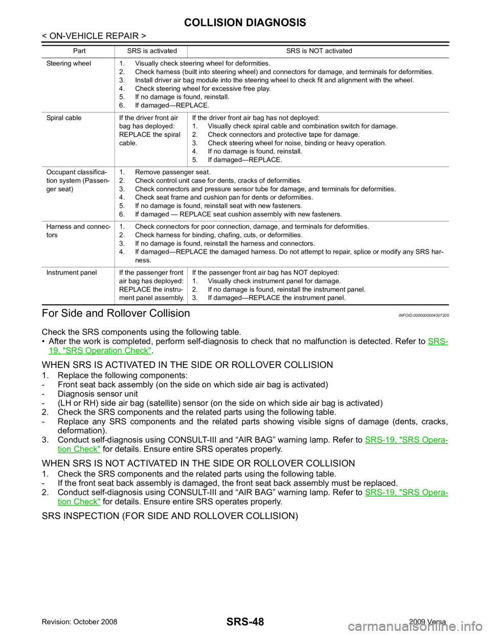
WHEN SRS IS ACTIVATED IN THE SIDE OR ROLLOVER COLLISION
1. Replace the following components:
- Front seat back assembly (on the side on which side air bag is activated)
- Diagnosis sensor unit
- (LH or RH) side air bag (satellite) sensor (on the side on which side air bag is activated)
2. Check the SRS components and the related parts using the following table.
- Replace any SRS components and the related parts showing visible signs of damage (dents, cracks, deformation).
3. Conduct self-diagnosis using CONSULT-III and “AIR BAG” warning lamp. Refer to SRS-19, " SRS Opera-
tion Check " for details. Ensure entire SRS operates properly.
WHEN SRS IS NOT ACTIVATED IN THE SIDE OR ROLLOVER COLLISION
1. Check the SRS components and the related parts using the following table.
- If the front seat back assembly is damaged, t he front seat back assembly must be replaced.
2. Conduct self-diagnosis using CONSULT-III and “AIR BAG” warning lamp. Refer to SRS-19, " SRS Opera-
tion Check " for details. Ensure entire SRS operates properly.
SRS INSPECTION (FOR SIDE AND ROLLOVER COLLISION) Steering wheel 1. Visually check steering wheel for deformities.
2. Check harness (built into steering wheel) and connectors for damage, and terminals for deformities.
3. Install driver air bag module into the steering wheel to check fit and alignment with the wheel.
4. Check steering wheel for excessive free play.
5. If no damage is found, reinstall.
6. If damaged—REPLACE.
Spiral cable If the driver front air bag has deployed:
REPLACE the spiral
cable. If the driver front air bag has not deployed:
1. Visually check spiral cable and combination switch for damage.
2. Check connectors and protective tape for damage.
3. Check steering wheel for noise, binding or heavy operation.
4. If no damage is found, reinstall.
5. If damaged—REPLACE.
Occupant classifica-
tion system (Passen-
ger seat) 1. Remove passenger seat.
2. Check control unit case for dents, cracks of deformities.
3. Check connectors and pressure sensor tube for damage, and terminals for deformities.
4. Check seat frame and cushion pan for dents or deformities.
5. If no damage is found, reinstall seat with new fasteners.
6. If damaged — REPLACE seat cushion assembly with new fasteners.
Harness and connec-
tors 1. Check connectors for poor connection, damage, and terminals for deformities.
2. Check harness for binding, chafing, cuts, or deformities.
3. If no damage is found, reinstall the harness and connectors.
4. If damaged—REPLACE the damaged harness. Do not attempt to repair, splice or modify any SRS har- ness.
Instrument panel If the passenger front air bag has deployed:
REPLACE the instru-
ment panel assembly. If the passenger front air bag has NOT deployed:
1. Visually check instrument panel for damage.
2. If no damage is found, reinstall the instrument panel.
3. If damaged—REPLACE the instrument panel.
Part SRS is activated SRS is NOT activated
Page 4253 of 4331

STC
N
O P
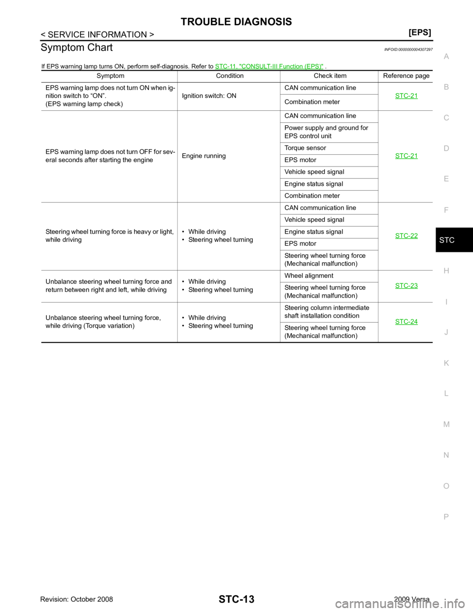
Symptom Chart
INFOID:0000000004307297
If EPS warning lamp turns ON, perform self-diagnosis. Refer to STC-11, " CONSULT-III Function (EPS) " .
Symptom Condition Check item Reference page
EPS warning lamp does not turn ON when ig-
nition switch to “ON”.
(EPS warning lamp check) Ignition switch: ONCAN communication line
STC-21 Combination meter
EPS warning lamp does not turn OFF for sev-
eral seconds after starting the engine Engine runningCAN communication line
STC-21 Power supply and ground for
EPS control unit
Torque sensor
EPS motor
Vehicle speed signal
Engine status signal
Combination meter
Steering wheel turning force is heavy or light,
while driving • While driving
• Steering wheel turning CAN communication line
STC-22 Vehicle speed signal
Engine status signal
EPS motor
Steering wheel turning force
(Mechanical malfunction)
Unbalance steering wheel turning force and
return between right and left, while driving • While driving
• Steering wheel turning Wheel alignment
STC-23 Steering wheel
turning force
(Mechanical malfunction)
Unbalance steering wheel turning force,
while driving (Torque variation) • While driving
• Steering wheel turning Steering column intermediate
shaft installation condition STC-24 Steering wheel
turning force
(Mechanical malfunction)
Page 4264 of 4331

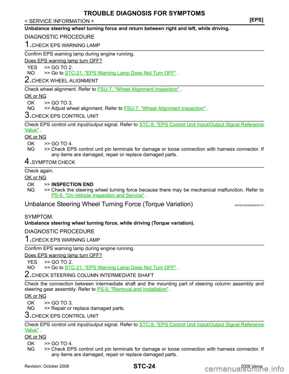
YES >> GO TO 2.
NO >> Go to STC-21, " EPS Warning Lamp Does Not Turn OFF " .
Wheel Alignment Inspection " .
OK or NG OK >> GO TO 3.
NG >> Adjust wheel alignment. Refer to FSU-7, " Wheel Alignment Inspection " .
EPS Control Unit Input/Output Signal Reference
Value " .
OK or NG OK >> GO TO 4.
NG >> Check EPS control unit pin terminals for dam age or loose connection with harness connector. If
any items are damaged, repair or replace damaged parts. OK >>
INSPECTION END
NG >> Check the steering wheel turning force because there may be mechanical malfunction. Refer to
PS-6, " On-Vehicle Inspection and Service " .
Unbalance Steering Wheel Turn ing Force (Torque Variation) INFOID:0000000004307311
SYMPTOM:
Unbalance steering wheel turning for ce, while driving (Torque variation).
DIAGNOSTIC PROCEDURE YES >> GO TO 2.
NO >> Go to STC-21, " EPS Warning Lamp Does Not Turn OFF " .
Removal and Installation " .
OK or NG OK >> GO TO 3.
NG >> Repair or replace damaged parts. EPS Control Unit Input/Output Signal Reference
Value " .
OK or NG OK >> GO TO 4.
NG >> Check EPS control unit pin terminals for dam age or loose connection with harness connector. If
any items are damaged, repair or replace damaged parts.