2009 NISSAN TIIDA headlamp
[x] Cancel search: headlampPage 448 of 4331
System Description " .
• Remote keyless entry system. Refer to BL-58, " System Description " .
• Power window system (with power windows). Refer to GW-19, " System Description " .
NOTE
• Sunroof system (with sunroof). Refer to RF-11, " System Description " .
NOTE
• Room lamp timer. Refer to LT-91, " System Description " .
• Rear wiper and washer system (Hatchback). Refer to WW-25, " System Description " .
NOTE:
Power supply only. No system control.
SYSTEMS CONTROLLED BY BCM AND IPDM E/R
• Panic system. Refer to BL-58, " System Description " .
• Vehicle security (theft warning) system. Refer to BL-219, " System Description " .
• NVIS(NATS) system. Refer to BL-248, " System Description " .
• Headlamp, tail lamp and battery saver control systems. Refer to LT-73, " System Description " ,
LT-4, " System
Description " or
LT-25, " System Description " .
• Front fog lamp (with front fog lamps). Refer to LT-39, " System Description " .
• Front wiper and washer system. Refer to WW-3, " System Description " .
• Rear window defogger system. Refer to GW-51, " System Description " .
SYSTEMS CONTROLLED BY BCM AND COMBINATION METER
• Warning chime. Refer to DI-42, " System Description " .
• Turn signal and hazard warning lamps. Refer to LT-48, " System Description " .
SYSTEMS CONTROLLED BY BCM AND INTELLIGENT KEY UNIT (WITH INTELLIGENT KEY)
• Intelligent Key system. Refer to BL-88, " System Description " .
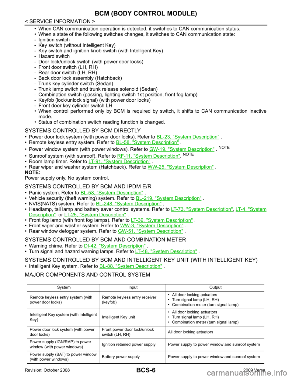
MAJOR COMPONENTS AND CONTROL SYSTEM
System Input Output
Remote keyless entry system (with
power door locks) Remote keyless entry receiver
(keyfob) • All door locking actuators
• Turn signal lamp (LH, RH)
• Combination meter (turn signal lamp)
Intelligent Key system (with Intelligent
Key) Intelligent Key unit• All door locking actuators
• Turn signal lamp (LH, RH)
• Combination meter (turn signal lamp)
Power door lock system (with power
door locks) Front power door lock/unlock
switch (LH, RH) All door locking actuators
Power supply (IGN/RAP) to power
window (with power windows) Ignition retained power supply Power supply to power window and sunroof system
Power supply (BAT) to power window
(with power windows) Battery power supply Power supply to power window and sunroof system
Page 449 of 4331

BCS
N
O P
CAN Communication System Description INFOID:0000000004306834
Refer to LAN-8, " System Description " .
Panic alarm
• Key switch
• Keyfob IPDM E/R
Vehicle security system • All door switches
• Keyfob
• Door lock/unlock switch
• Trunk key cylinder switch (Se-
dan)
• Front door key cylinder switch LH • IPDM/ER
• Security indicator lamp
Battery saver control • Ignition switch
• Combination switch IPDM E/R
Headlamp Combination switch IPDM E/R
Tail lamp Combination switch IPDM E/R
Front fog lamp (with front fog lamps) Combination switch IPDM E/R
Turn signal lamp Combination switch • Turn signal lamp
• Combination meter
Hazard lamp Hazard switch • Turn signal lamp
• Combination meter
Room lamp timer • Key switch
• Keyfob
• Main power window and door lock/unlock switch
• Front door switch LH
• All door switch Interior room lamp
Back door switch signal (Hatchback) Back door lock assembly Luggage room lamp
Back door lock signal (Hatchback) Back door lock assembly Back door opener
Trunk lamp switch signal (Sedan) Trunk lamp switch and trunk re-
lease solenoid Luggage room lamp
Trunk lid opener signal (Sedan) Trunk lamp switch and trunk re-
lease solenoid Trunk lid opener
Key warning chime • Key switch
• Front door switch LH Combination meter (warning buzzer)
Light warning chime • Combination switch
• Key switch
• Front door switch LH Combination meter (warning buzzer)
Seat belt warning chime • Seat belt buckle switch LH
• Ignition switch Combination meter (warning buzzer)
Front wiper and washer system • Combination switch
• Ignition switch IPDM E/R
Rear window defogger Rear window defogger switch IPDM E/R
Rear wiper and washer system
(Hatchback) • Combination switch
• Ignition switch Rear wiper motor
A/C switch signal Front air control ECM
Blower fan switch signal Front air control ECM
A/C indicator signal Front air control A/C indicator
Low tire pressure warning system Remote keyless entry receiver Combination meter System Input Output
Page 474 of 4331
BL
N
O P
HOOD
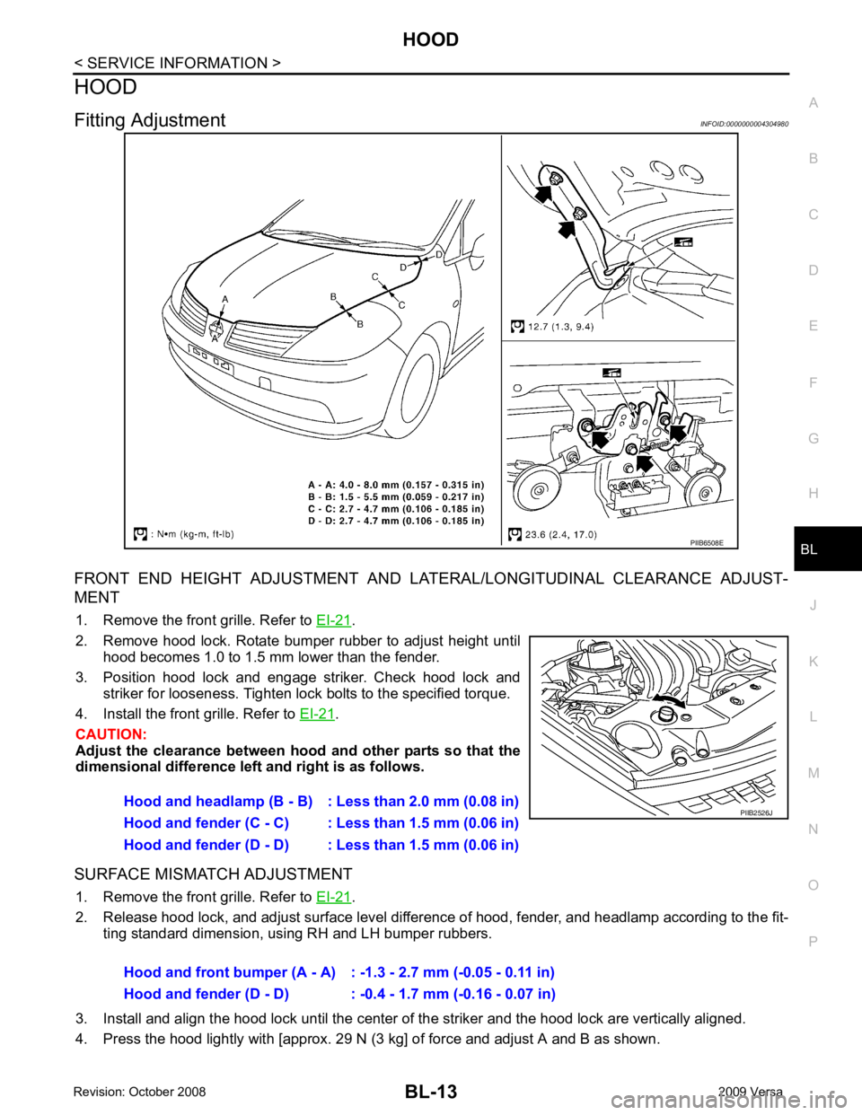
Fitting Adjustment INFOID:0000000004304980
FRONT END HEIGHT ADJUSTMENT AND LA TERAL/LONGITUDINAL CLEARANCE ADJUST-
MENT
1. Remove the front grille. Refer to EI-21 .
2. Remove hood lock. Rotate bumper rubber to adjust height until hood becomes 1.0 to 1.5 mm lower than the fender.
3. Position hood lock and engage striker. Check hood lock and striker for looseness. Tighten lock bolts to the specified torque.
4. Install the front grille. Refer to EI-21 .
CAUTION:
Adjust the clearance between hood and other parts so that the
dimensional difference left and right is as follows.
SURFACE MISMATCH ADJUSTMENT 1. Remove the front grille. Refer to EI-21 .
2. Release hood lock, and adjust surface level difference of hood, fender, and headlamp according to the fit- ting standard dimension, using RH and LH bumper rubbers.
3. Install and align the hood lock until the center of the striker and the hood lock are vertically aligned.
4. Press the hood lightly with [approx. 29 N (3 kg] of force and adjust A and B as shown.
Page 480 of 4331
BL
N
O P
RADIATOR CORE SUPPORT
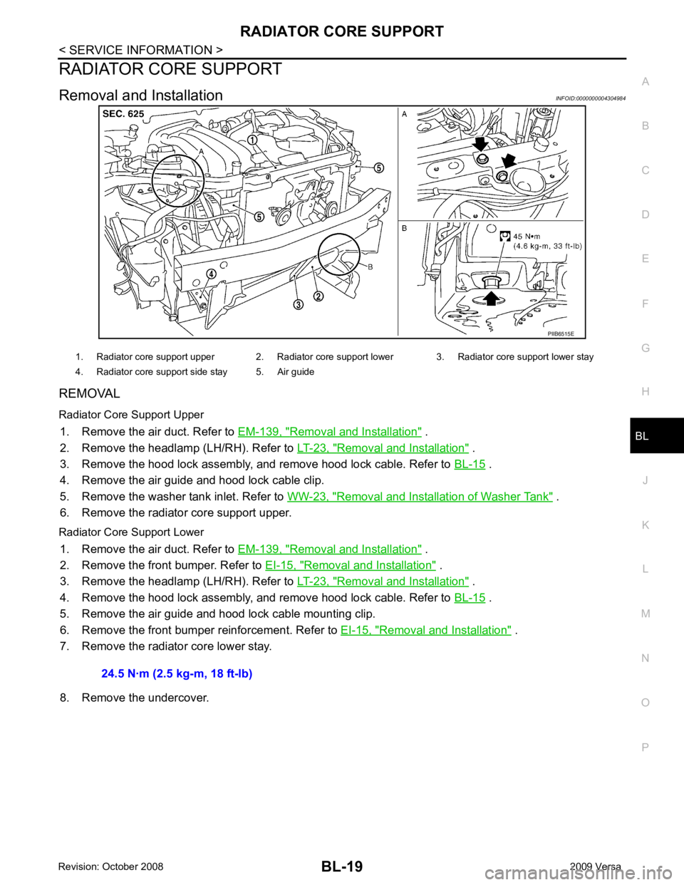
Removal and Installation INFOID:0000000004304984
REMOVAL
Radiator Core Support Upper 1. Remove the air duct. Refer to EM-139, " Removal and Installation " .
2. Remove the headlamp (LH/RH). Refer to LT-23, " Removal and Installation " .
3. Remove the hood lock assembly, and remove hood lock cable. Refer to BL-15 .
4. Remove the air guide and hood lock cable clip.
5. Remove the washer tank inlet. Refer to WW-23, " Removal and Installation of Washer Tank " .
6. Remove the radiator core support upper.
Radiator Core Support Lower 1. Remove the air duct. Refer to EM-139, " Removal and Installation " .
2. Remove the front bumper. Refer to EI-15, " Removal and Installation " .
3. Remove the headlamp (LH/RH). Refer to LT-23, " Removal and Installation " .
4. Remove the hood lock assembly, and remove hood lock cable. Refer to BL-15 .
5. Remove the air guide and hood lock cable mounting clip.
6. Remove the front bumper reinforcement. Refer to EI-15, " Removal and Installation " .
7. Remove the radiator core lower stay.
8. Remove the undercover.
Page 482 of 4331
BL
N
O P
FRONT FENDER
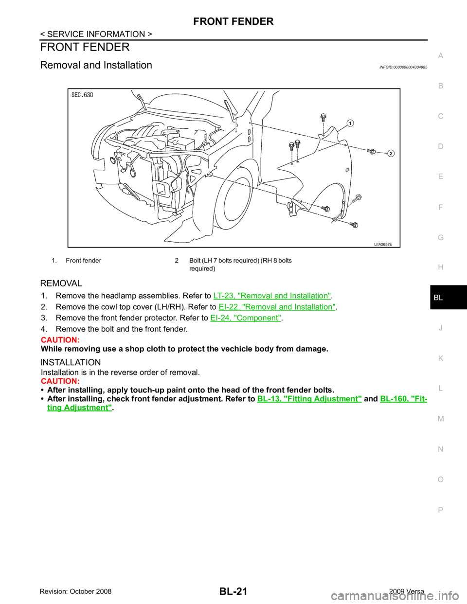
Removal and Installation INFOID:0000000004304985
REMOVAL 1. Remove the headlamp assemblies. Refer to LT-23, " Removal and Installation " .
2. Remove the cowl top cover (LH/RH). Refer to EI-22, " Removal and Installation " .
3. Remove the front fender protector. Refer to EI-24, " Component " .
4. Remove the bolt and the front fender.
CAUTION:
While removing use a shop cloth to pr otect the vechicle body from damage.
INSTALLATION Installation is in the reverse order of removal.
CAUTION:
• After installing, apply touch-up paint on to the head of the front fender bolts.
• After installing, check front fender adjustment. Refer to BL-13, " Fitting Adjustment " and
BL-160, " Fit-
ting Adjustment " .
1. Front fender 2 Bolt (LH 7 bolts required) (RH 8 bolts
required)
Page 552 of 4331
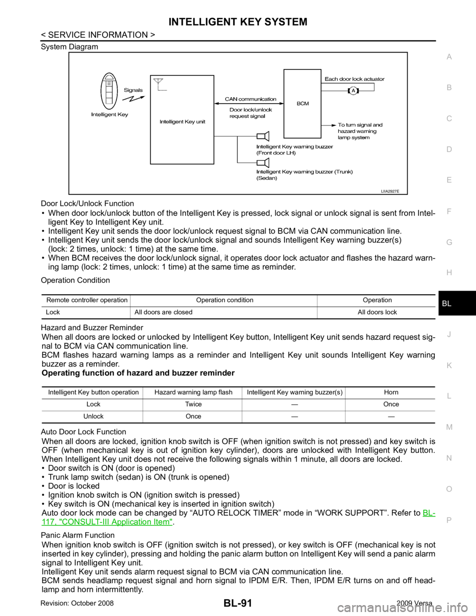
BL
N
O P
System Diagram
Door Lock/Unlock Function • When door lock/unlock button of the Intelligent Key is pr essed, lock signal or unlock signal is sent from Intel-
ligent Key to Intelligent Key unit.
• Intelligent Key unit sends the door lock/unlock request signal to BCM via CAN communication line.
• Intelligent Key unit sends the door lock/unlock signal and sounds Intelligent Key warning buzzer(s) (lock: 2 times, unlock: 1 time) at the same time.
• When BCM receives the door lock/unlock signal, it oper ates door lock actuator and flashes the hazard warn-
ing lamp (lock: 2 times, unlock: 1 time) at the same time as reminder.
Operation Condition
Hazard and Buzzer Reminder When all doors are locked or unlocked by Intelligent Ke y button, Intelligent Key unit sends hazard request sig-
nal to BCM via CAN communication line.
BCM flashes hazard warning lamps as a reminder and Intelligent Key unit sounds Intelligent Key warning
buzzer as a reminder.
Operating function of hazard and buzzer reminder
Auto Door Lock Function When all doors are locked, ignition knob switch is OFF (when ignition switch is not pressed) and key switch is
OFF (when mechanical key is out of ignition key cyli nder), doors are unlocked with Intelligent Key button.
When Intelligent Key unit does not receive the following signals within 1 minute, all doors are locked.
• Door switch is ON (door is opened)
• Trunk lamp switch (sedan) is ON (trunk is opened)
• Door is locked
• Ignition knob switch is ON (ignition switch is pressed)
• Key switch is ON (mechanical key is inserted in ignition switch)
Auto door lock mode can be changed by “AUTO RELOCK TIMER” mode in “WORK SUPPORT”. Refer to BL-117, " CONSULT-III Application Item " .
Panic Alarm Function When ignition knob switch is OFF (ignition switch is not pressed), or key switch is OFF (mechanical key is not
inserted in key cylinder), pressing and holding the panic alarm button on Intelligent Key will send a panic alarm
signal to Intelligent Key unit.
Intelligent Key unit sends alarm request signal to BCM via CAN communication line.
BCM sends headlamp request signal and horn signal to IPDM E/R. Then, IPDM E/R turns on and off head-
lamp and horn intermittently. Intelligent Key button operation Hazard warning lamp flash Intelligent Key warning buzzer(s) Horn
Lock Twice — Once
Unlock Once — —
Page 584 of 4331
BL
N
O P
NOTE:
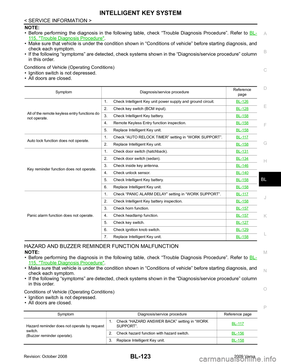
• Before performing the diagnosis in the following table, check “Trouble Diagnosis Procedure”. Refer to BL-115, " Trouble Diagnosis Procedure " .
• Make sure that vehicle is under the condition shown in “Conditions of vehicle” before starting diagnosis, and
check each symptom.
• If the following “symptoms” are detected, check syst ems shown in the “Diagnosis/service procedure” column
in this order.
Conditions of Vehicle (Operating Conditions) • Ignition switch is not depressed.
• All doors are closed.
HAZARD AND BUZZER REMINDER FUNCTION MALFUNCTION NOTE:
• Before performing the diagnosis in the following table, check “Trouble Diagnosis Procedure”. Refer to BL-115, " Trouble Diagnosis Procedure " .
• Make sure that vehicle is under the condition shown in “Conditions of vehicle” before starting diagnosis, and
check each symptom.
• If the following “symptoms” are detected, check syst ems shown in the “Diagnosis/service procedure” column
in this order.
Conditions of Vehicle (Operating Conditions) • Ignition switch is not depressed.
• All doors are closed. Symptom Diagnosis/service procedure
Reference
page
All of the remote keyless entry functions do
not operate. 1. Check Intelligent Key unit power supply and ground circuit.
BL-1262. Check key switch (BCM input).
BL-1283. Check Intelligent Key battery.
BL-1584. Remote Keyless Entry function inspection.
BL-1585. Replace Intelligent Key unit.
BL-158Auto lock function does not operate.
1. Check “AUTO RELOCK TIMER”
setting in “WORK SUPPORT”. BL-117 2. Replace Intelligent Key unit.
BL-158Key reminder function does not operate.
1. Check door switch (hatchback).
BL-1312. Check door switch (sedan).
BL-1343. Check inside key antenna.
BL-1464. Check unlock sensor.
BL-1405. Check Intelligent Key battery.
BL-1586. Replace Intelligent Key unit.
BL-158Panic alarm function does not operate.
1. Check “PANIC ALARM DELAY” setting in “WORK SUPPORT”.
BL-1172. Check Intelligent Key battery inspection.
BL-1583. Check horn function.
BL-1574. Check headlamp function.
BL-1575. Check key switch.
BL-1276. Check ignition knob switch.
BL-1297. Replace Intelligent Key unit.
BL-158Symptom Diagnosis/service procedure Reference page
Hazard reminder does not operate by request
switch.
(Buzzer reminder operate). 1. Check “HAZARD ANSWER BACK” setting in “WORK
SUPPORT”. BL-1172. Check hazard function with hazard switch.
BL-1563. Replace Intelligent Key unit.
BL-158
Page 618 of 4331
INTELLIGENT KEY SYSTEM
BL-157
< SERVICE INFORMATION >
C
D E
F
G H
J
K L
M A
B BL
N
O P
Horn Function Check
INFOID:0000000004305072
First perform the “SELF-DIAG RESULTS” of “BCM” with CONSULT-III, then perform the trouble diag-
nosis of malfunction system indicated in “ SELF-DIAG RESULTS” of “BCM”. Refer to BCS-17, " CAN
Communication Inspection Using CONSULT-III (Self-Diagnosis) " .
1.
CHECK HORN OPERATION
Check if horn sounds with horn switch.
Does horn operate? Yes >> GO TO 2
No >> Check horn circuit. Refer to WW-38 .
2.
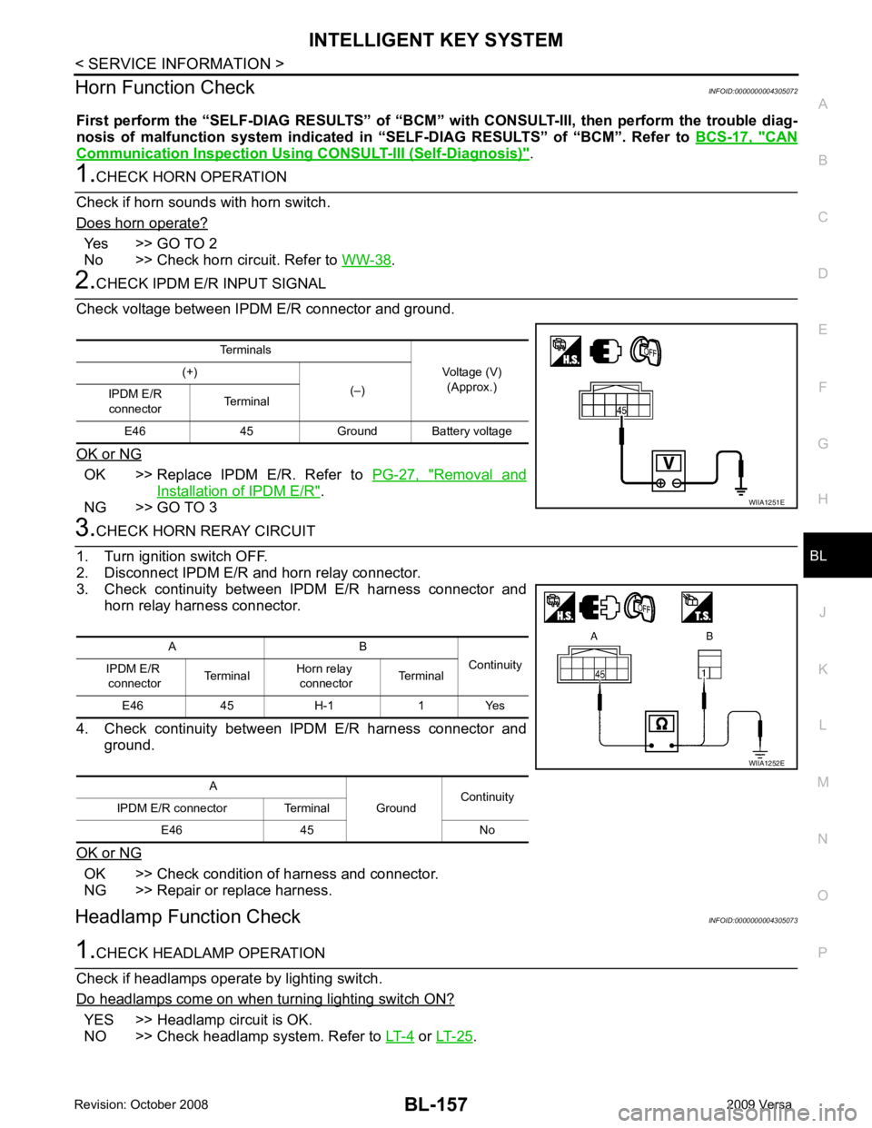
CHECK IPDM E/R INPUT SIGNAL
Check voltage between IPDM E/R connector and ground.
OK or NG OK >> Replace IPDM E/R. Refer to
PG-27, " Removal and
Installation of IPDM E/R " .
NG >> GO TO 3 3.
CHECK HORN RERAY CIRCUIT
1. Turn ignition switch OFF.
2. Disconnect IPDM E/R and horn relay connector.
3. Check continuity between IPDM E/R harness connector and horn relay harness connector.
4. Check continuity between IPDM E/R harness connector and ground.
OK or NG OK >> Check condition of harness and connector.
NG >> Repair or replace harness.
Headlamp Function Check INFOID:00000000043050731.
CHECK HEADLAMP OPERATION
Check if headlamps operate by lighting switch.
Do headlamps come on when turning lighting switch ON? YES >> Headlamp circuit is OK.
NO >> Check headlamp system. Refer to LT-4 or
LT-25 .
Terminals
Voltage (V)(Approx.)
(+)
(–)
IPDM E/R
connector Terminal
E46 45 Ground Ba ttery voltage WIIA1251E
A B
Continuity
IPDM E/R
connector Terminal
Horn relay
connector Terminal
E46 45 H-1 1 Yes
A GroundContinuity
IPDM E/R connector Terminal
E46 45 No WIIA1252E