Page 937 of 4331
CO
NP
O
WATER PUMP
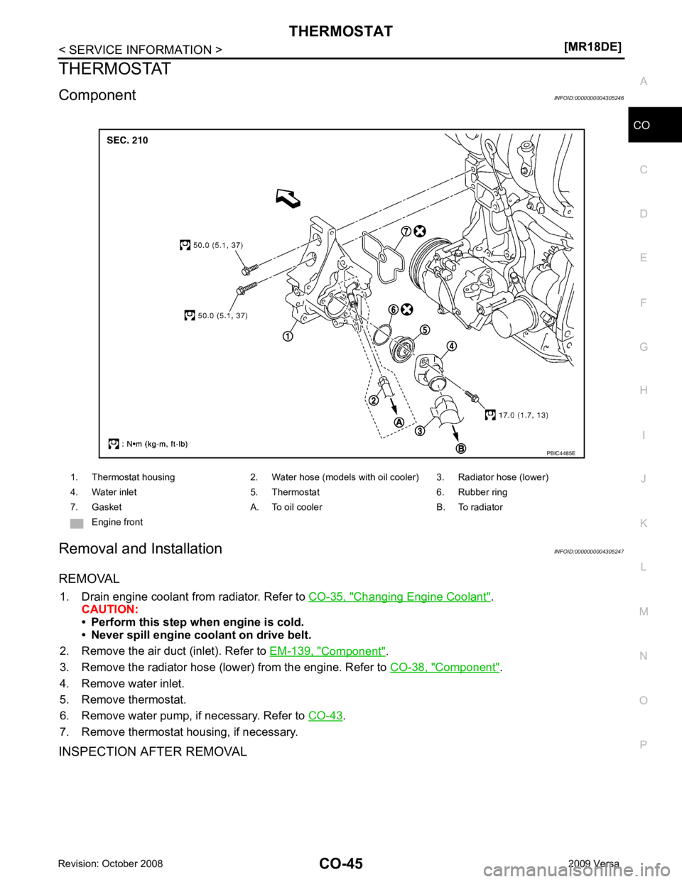
Component INFOID:0000000004305244
Removal and Installation INFOID:0000000004305245
REMOVAL 1. Drain engine coolant from radiator. Refer to CO-35, " Changing Engine Coolant " .
CAUTION:
Perform this step when the engine is cold.
2. Remove fender protector (RH). Refer to EI-24, " Removal and Installation " .
3. Remove drive belt. Refer to EM-136, " Removal and Installation " .
4. Remove generator. Refer to SC-25, " Removal and Installation " .
5. Remove radiator hose (lower). Refer to CO-38, " Component " .
6. Remove water pump. CAUTION:
• Handle water pump vane so that it does not contact any other parts.
• Water pump cannot be disassembled and should be replaced as a unit.
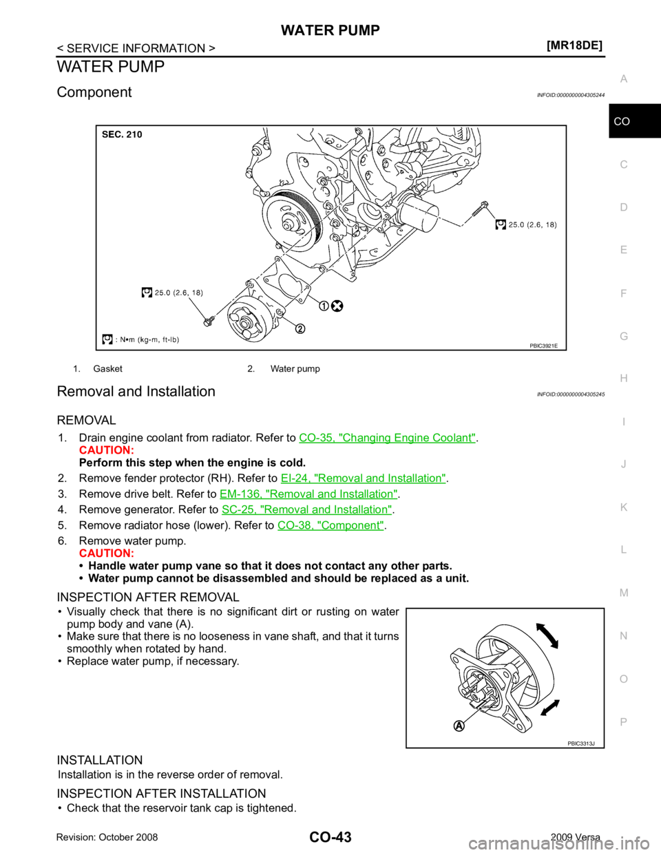
INSPECTION AFTER REMOVAL • Visually check that there is no significant dirt or rusting on water pump body and vane (A).
• Make sure that there is no looseness in vane shaft, and that it turns
smoothly when rotated by hand.
• Replace water pump, if necessary.
INSTALLATION Installation is in the reverse order of removal.
INSPECTION AFTER INSTALLATION • Check that the reservoir tank cap is tightened. 1. Gasket 2. Water pump
PBIC3313J
Page 939 of 4331
CO
NP
O
THERMOSTAT
Component INFOID:0000000004305246
Removal and Installation INFOID:0000000004305247
REMOVAL 1. Drain engine coolant from radiator. Refer to CO-35, " Changing Engine Coolant " .
CAUTION:
• Perform this step when engine is cold.
• Never spill engine coolant on drive belt.
2. Remove the air duct (inlet). Refer to EM-139, " Component " .
3. Remove the radiator hose (lower) from the engine. Refer to CO-38, " Component " .
4. Remove water inlet.
5. Remove thermostat.
6. Remove water pump, if necessary. Refer to CO-43 .
7. Remove thermostat housing, if necessary.
INSPECTION AFTER REMOVAL 1. Thermostat housing 2. Water hose (models with oil cooler) 3. Radiator hose (lower)
4. Water inlet 5. Thermostat 6. Rubber ring
7. Gasket A. To oil cooler B. To radiator Engine front
Page 941 of 4331
CO
NP
O
WATER OUTLET AND WATER CONTROL VALVE
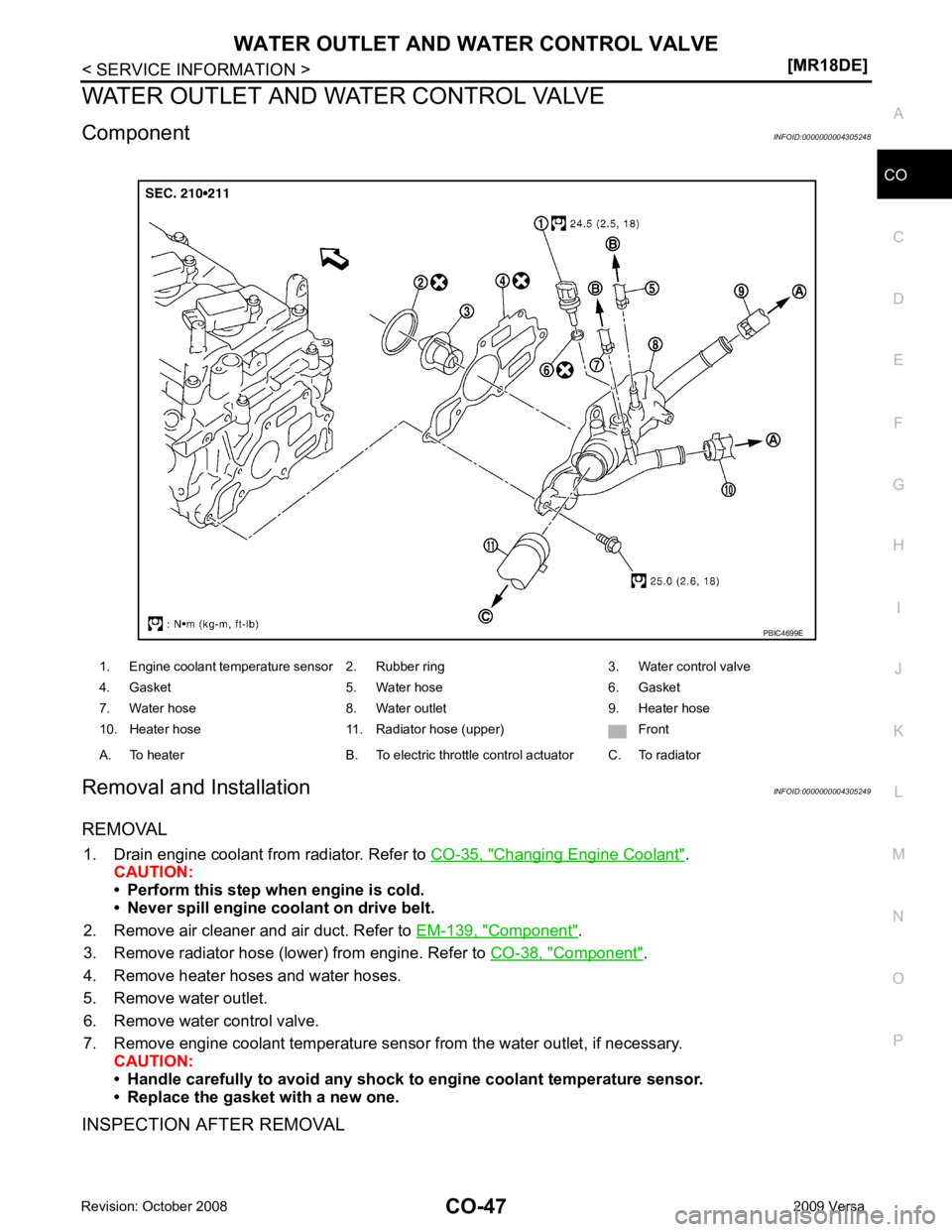
Component INFOID:0000000004305248
Removal and Installation INFOID:0000000004305249
REMOVAL 1. Drain engine coolant from radiator. Refer to CO-35, " Changing Engine Coolant " .
CAUTION:
• Perform this step when engine is cold.
• Never spill engine coolant on drive belt.
2. Remove air cleaner and air duct. Refer to EM-139, " Component " .
3. Remove radiator hose (lower) from engine. Refer to CO-38, " Component " .
4. Remove heater hoses and water hoses.
5. Remove water outlet.
6. Remove water control valve.
7. Remove engine coolant temperature sensor from the water outlet, if necessary. CAUTION:
• Handle carefully to avoid any shock to engine coolant temperature sensor.
• Replace the gasket with a new one.
INSPECTION AFTER REMOVAL 1. Engine coolant temperature sensor 2. Rubber ring 3. Water control valve
4. Gasket 5. Water hose 6. Gasket
7. Water hose 8. Water outlet 9. Heater hose
10. Heater hose 11. Radiator hose (upper) Front
A. To heater B. To electric throttle control actuator C. To radiator
Page 959 of 4331

PRECAUTIONS
CVT-15
< SERVICE INFORMATION >
[RE0F08A] D
E
F
G H
I
J
K L
M A
B CVT
N
O P
•
Before replacing TCM, perform TCM input/output signal
inspection and make sure whether TCM functions properly or
not. CVT-49, " TCM Terminal and Reference Value " .
• After performing each TROUBL E DIAGNOSIS, perform “DTC
Confirmation Procedure”.
If the repair is completed the DTC should not be displayed in
the “DTC Confirmation Procedure”.
• Always use the specified br and of CVT fluid. Refer to MA-14, " Flu-
ids and Lubricants " .
• Use lint-free paper, not cloth rags, during work.
• After replacing the CVT fluid, dispose of the waste oil using the methods prescribed by law, ordinance, etc.
Service Notice or Precaution INFOID:0000000004666859
CVT FLUID COOLER SERVICE If CVT fluid contains friction material (clutches, brakes , etc.), or if an CVT is replaced, inspect and clean the
CVT fluid cooler mounted in the radiator or replace t he radiator. Flush cooler lines using cleaning solvent and
compressed air after repair. For CVT fluid cooler cleaning procedure, refer to CVT-18, " CVT Fluid Cooler
Cleaning " . For radiator replacement, refer to
CO-38 .
OBD-II SELF-DIAGNOSIS • CVT self-diagnosis is performed by the TCM in comb ination with the ECM. The results can be read through
the blinking pattern of the malfunction indi cator lamp (MIL). Refer to the table on CVT-51, " CONSULT-III
Function (TRANSMISSION) " for the indicator used to display each self-diagnostic result.
• The self-diagnostic results indicated by the MIL ar e automatically stored in both the ECM and TCM memo-
ries.
Always perform the procedure on CVT-30, " OBD-II Diagnostic Trouble Code (DTC) " to complete the
repair and avoid unnecessary blinking of the MIL.
For details of OBD-II, refer to EC-541, " Introduction " .
• Certain systems and components, especially those re lated to OBD, may use the new style slide-lock-
ing type harness connector. For descripti on and how to disconnect, refer to PG-64 . MEF040DA
SEF217U
Page 962 of 4331
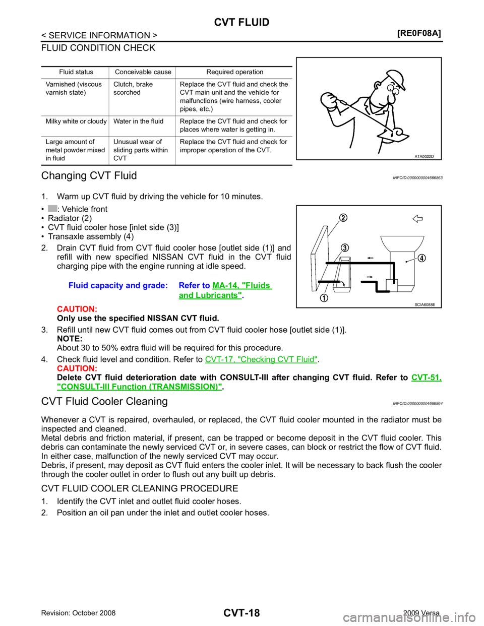
Checking CVT Fluid " .
CAUTION:
Delete CVT fluid deterioration date with CONS ULT-III after changing CVT fluid. Refer to CVT-51," CONSULT-III Function (TRANSMISSION) " .
CVT Fluid Cooler Cleaning INFOID:0000000004666864
Whenever a CVT is repaired, overhauled, or replaced, t he CVT fluid cooler mounted in the radiator must be
inspected and cleaned.
Metal debris and friction material, if present, can be tr apped or become deposit in the CVT fluid cooler. This
debris can contaminate the newly serviced CVT or, in severe cases, can block or restrict the flow of CVT fluid.
In either case, malfunction of the newly serviced CVT may occur.
Debris, if present, may deposit as CVT fluid enters the cooler inlet. It will be necessary to back flush the cooler
through the cooler outlet in order to flush out any built up debris.
CVT FLUID COOLER CLEANING PROCEDURE
1. Identify the CVT inlet and outlet fluid cooler hoses.
2. Position an oil pan under the inlet and outlet cooler hoses. Fluid status Conceivable cause Required operation
Varnished (viscous
varnish state) Clutch, brake
scorched Replace the CVT fluid and check the
CVT main unit and the vehicle for
malfunctions (wire harness, cooler
pipes, etc.)
Milky white or cloudy Water in the fluid Replace the CVT fluid and check for places where water is getting in.
Large amount of
metal powder mixed
in fluid Unusual wear of
sliding parts within
CVT Replace the CVT fluid and check for
improper operation of the CVT. Fluids
and Lubricants " .
Page 964 of 4331

CVT-20< SERVICE INFORMATION >
[RE0F08A]
CVT FLUID
3. Insert the extension adapter hose of a can of Transmission
Cooler Cleaner (Nissan P/N 999MP-AM006) into the cooler out-
let hose.
CAUTION:
• Wear safety glasses and rubber gloves when spraying the Transmission Cooler Cleaner.
• Spray Transmission Cooler Cleaner only with adequate
ventilation.
• Avoid contact with eyes and skin.
• Do not breath vapors or spray mist.
4. Hold the hose and can as high as possible and spray Transmis- sion Cooler Cleaner in a continuous stream into the cooler outlet
hose until CVT fluid flows out of the cooler inlet hose for 5 seconds.
5. Tie a common white, basket-type coffee filter to the end of the cooler inlet hose.
6. Insert the tip of an air gun into the end of the cooler outlet hose.
7. Wrap a shop rag around the air gun tip and end of cooler outlet hose.
8. Blow compressed air regulated to 5 to 9 kg/cm 2
(71 to 128 psi)
through the cooler outlet hose to force any remaining CVT fluid
into the coffee filter.
9. Remove the coffee filter from the end of the cooler inlet hose.
10. Perform "CVT FLUID COOLER INSPECTION PROCEDURE".
CVT FLUID COOLER INSPECTION PROCEDURE
1. Inspect the coffee filter for debris.
a. If small metal debris less than 1 mm (0.040 in) in size or metal powder is found in the coffee filter, this is normal. If normal
debris is found, the CVT fluid cooler/radiator can be re-used and
the procedure is ended. SCIA4421E
SCIA4424E
SCIA4425E
SCIA2967E
Page 965 of 4331
CVT
N
O P
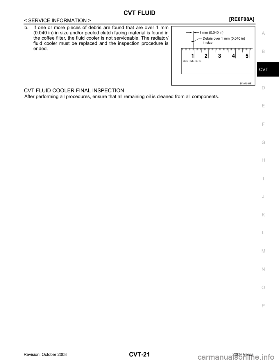
b. If one or more pieces of debr
is are found that are over 1 mm
(0.040 in) in size and/or peeled clutch facing material is found in
the coffee filter, the fluid cooler is not serviceable. The radiator/
fluid cooler must be replaced and the inspection procedure is
ended.
CVT FLUID COOLER FINAL INSPECTION After performing all procedures, ensure that all remaining oil is cleaned from all components.
Page 1137 of 4331

PRECAUTIONS
CVT-193
< SERVICE INFORMATION >
[RE0F08B] D
E
F
G H
I
J
K L
M A
B CVT
N
O P
•
Before connecting or disconn ecting the TCM harness connec-
tor, turn ignition switch OF F and disconnect negative battery
cable. Because battery voltage is applied to TCM even if igni-
tion switch is turned OFF.
• When connecting or disconnect ing pin connectors into or
from TCM, take care not to damage pin terminals (bend or
break).
When connecting pin connectors make sure that there are not
any bends or breaks on TCM pin terminal.
• Before replacing TCM, perform TCM input/output signal
inspection and make sure whether TCM functions properly or
not. CVT-228, " TCM Terminal and Reference Value " .
• After performing each TROUBL E DIAGNOSIS, perform “DTC
Confirmation Procedure”.
If the repair is completed the DTC should not be displayed in
the “DTC Confirmation Procedure”.
• Always use the specified br and of CVT fluid. Refer to MA-14, " Flu-
ids and Lubricants " .
• Use lint-free paper, not cloth rags, during work.
• After replacing the CVT fluid, dispose of the waste oil using the methods prescribed by law, ordinance, etc.
Service Notice or Precaution INFOID:0000000004305567
CVT FLUID COOLER SERVICE If CVT fluid contains friction material (clutches, brakes , etc.), or if an CVT is replaced, inspect and clean the
CVT fluid cooler mounted in the radiator or replace t he radiator. Flush cooler lines using cleaning solvent and
compressed air after repair. For CVT fluid cooler cleaning procedure, refer to CVT-197, " CVT Fluid Cooler
Cleaning " . For radiator replacement, refer to
CO-38 .
OBD-II SELF-DIAGNOSIS SEF289H
SEF291H
MEF040DA
SEF217U