2009 NISSAN LATIO maintenance
[x] Cancel search: maintenancePage 3087 of 4331
![NISSAN LATIO 2009 Service Repair Manual EM-140< SERVICE INFORMATION >
[MR18DE]
AIR CLEANER AND AIR DUCT
• Align marks.
• Attach each joint securely.
• Screw clamps firmly.
Changing Air Cleaner Filter INFOID:0000000004307131
REMOVAL
1.](/manual-img/5/57359/w960_57359-3086.png "NISSAN LATIO 2009 Service Repair Manual EM-140< SERVICE INFORMATION >
[MR18DE]
AIR CLEANER AND AIR DUCT
• Align marks.
• Attach each joint securely.
• Screw clamps firmly.
Changing Air Cleaner Filter INFOID:0000000004307131
REMOVAL
1.")
EM-140< SERVICE INFORMATION >
[MR18DE]
AIR CLEANER AND AIR DUCT
• Align marks.
• Attach each joint securely.
• Screw clamps firmly.
Changing Air Cleaner Filter INFOID:0000000004307131
REMOVAL
1. Push the tabs (A) of both ends of the air cleaner cover (1) into the inside (B).
2. Pull up the air cleaner cover (1) and remove it (C).
3. Remove the air cleaner filter (1) and holder (2) assembly from the air cleaner case.
4. Remove the air cleaner filter (1) from the holder (2).
INSPECTION AFTER REMOVAL
It is necessary to replace the air cleaner filter at the recommended intervals, more often under dusty driving
conditions. Refer to MA-9, " Introduction of Periodic Maintenance " .
INSTALLATION
Installation is in the reverse order of removal.
• Install the air cleaner cover (1) in the direction shown.
• Air cleaner filter (2)
• Holder (3) PBIC3557J
PBIC3558J
PBIC3559J
Page 3191 of 4331
EX
NP
O
SERVICE INFORMATION
PRECAUTIONS
Precaution for Supplemental Restraint System (SRS) "AIR BAG" and "SEAT BELT
PRE-TENSIONER" INFOID:0000000004784390
The Supplemental Restraint System such as “A IR BAG” and “SEAT BELT PRE-TENSIONER”, used along
with a front seat belt, helps to reduce the risk or severi ty of injury to the driver and front passenger for certain
types of collision. This system includes seat belt switch inputs and dual stage front air bag modules. The SRS
system uses the seat belt switches to determine the front air bag deployment, and may only deploy one front
air bag, depending on the severity of a collision and w hether the front occupants are belted or unbelted.
Information necessary to service the system safely is included in the SRS and SB section of this Service Man-
ual.
WARNING:
• To avoid rendering the SRS inoper ative, which could increase the risk of personal injury or death in
the event of a collision which would result in air bag inflation, all maintenance must be performed by
an authorized NISSAN/INFINITI dealer.
• Improper maintenance, including in correct removal and installation of the SRS can lead to personal
injury caused by unintentional act ivation of the system. For removal of Spiral Cable and Air Bag
Module, see the SRS section.
• Do not use electrical test equipm ent on any circuit related to the SRS unless instructed to in this
Service Manual. SRS wiring harnesses can be identi fied by yellow and/or orange harnesses or har-
ness connectors.
• When working near the Airbag Diagnosis Sensor Un it or other Airbag System sensors with the Igni-
tion ON or engine running, DO NOT use air or el ectric power tools or strike near the sensor(s) with a
hammer. Heavy vibration could activate the sensor( s) and deploy the air bag(s), possibly causing
serious injury.
• When using air or electric power tools or hammers , always switch the Ignition OFF, disconnect the
battery, and wait at least 3 minutes before performing any service.
Precaution Necessary for Steering Wh eel Rotation After Battery Disconnect
INFOID:0000000004675325
NOTE:
• This Procedure is applied only to models with Inte lligent Key system and NATS (NISSAN ANTI-THEFT SYS-
TEM).
• Remove and install all control units after disconnecti ng both battery cables with the ignition knob in the
″ LOCK ″ position.
• Always use CONSULT-III to perform self-diagnosis as a part of each function inspection after finishing work.
If DTC is detected, perform trouble diagnosis according to self-diagnostic results.
For models equipped with the Intelligent Key system and NATS , an electrically controlled steering lock mech-
anism is adopted on the key cylinder.
For this reason, if the battery is disconnected or if the battery is discharged, the steering wheel will lock and
steering wheel rotation will become impossible.
If steering wheel rotation is required when battery pow er is interrupted, follow the procedure below before
starting the repair operation.
OPERATION PROCEDURE 1. Connect both battery cables. NOTE:
Supply power using jumper cables if battery is discharged.
2. Use the Intelligent Key or mechanical key to turn the ignition switch to the ″ACC ″ position. At this time, the
steering lock will be released.
3. Disconnect both battery cables. The steering lock will remain released and the steering wheel can be
rotated.
4. Perform the necessary repair operation.
5. When the repair work is completed, return the ignition switch to the ″LOCK ″ position before connecting
the battery cables. (At this time, the steering lock mechanism will engage.)
6. Perform a self-diagnosis check of al l control units using CONSULT-III.
Page 3201 of 4331
Removal and Installation " .
CAUTION:
The wheel hub assembly does not requ ire maintenance. If any of the following symptoms are noted,
replace the wheel hub assembly.
• Growling noise is emitted from the wheel hub bearing during operation.
• Wheel hub bearing drags or turns roughly.
Removal and Installation INFOID:0000000004305844
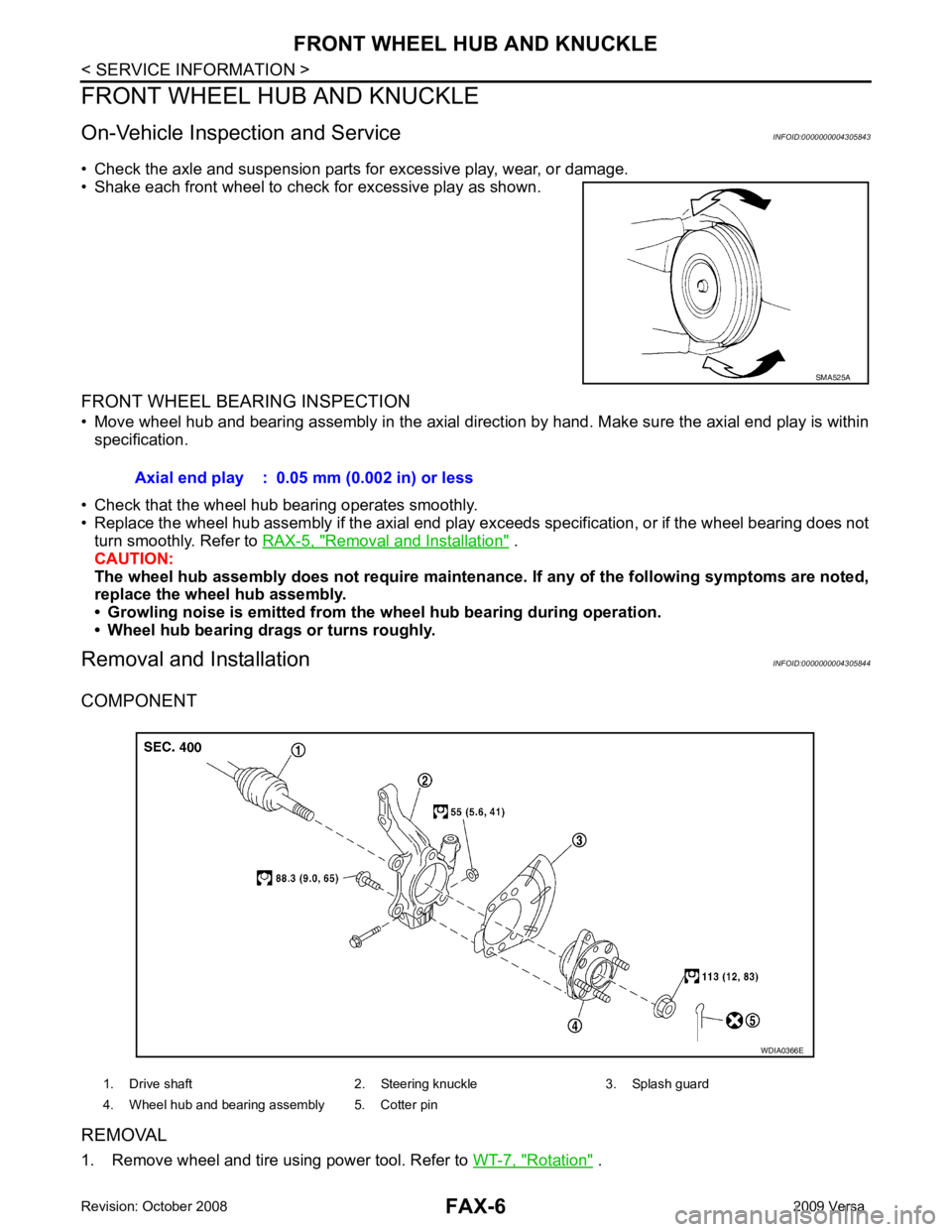
COMPONENT
REMOVAL
1. Remove wheel and tire using power tool. Refer to WT-7, " Rotation " .
Page 3203 of 4331
FAX-8< SERVICE INFORMATION >
FRONT WHEEL HUB AND KNUCKLE
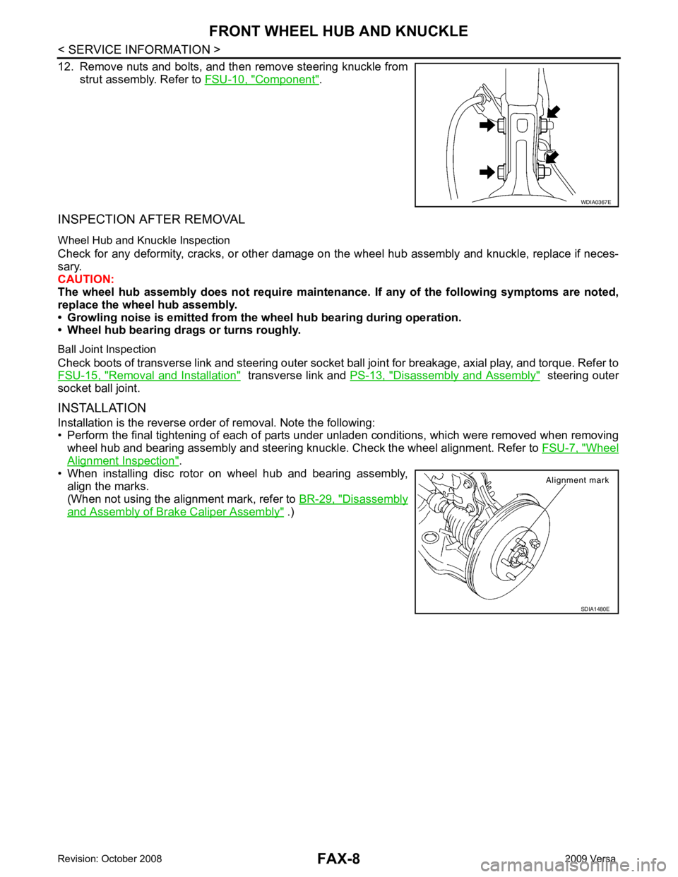
12. Remove nuts and bolts, and then remove steering knuckle from strut assembly. Refer to FSU-10, " Component " .
INSPECTION AFTER REMOVAL
Wheel Hub and Knuckle Inspection
Check for any deformity, cracks, or other damage on t he wheel hub assembly and knuckle, replace if neces-
sary.
CAUTION:
The wheel hub assembly does not require maintenance. If any of the following symptoms are noted,
replace the wheel hub assembly.
• Growling noise is emitted from the wheel hub bearing during operation.
• Wheel hub bearing drags or turns roughly.
Ball Joint Inspection
Check boots of transverse link and steering outer socket ball joint for breakage, axial play, and torque. Refer to
FSU-15, " Removal and Installation " transverse link and
PS-13, " Disassembly and Assembly " steering outer
socket ball joint.
INSTALLATION
Installation is the reverse order of removal. Note the following:
• Perform the final tightening of each of parts under unladen conditions, which were removed when removing
wheel hub and bearing assembly and steering knuckl e. Check the wheel alignment. Refer to FSU-7, " Wheel
Alignment Inspection " .
• When installing disc rotor on wheel hub and bearing assembly,
align the marks.
(When not using the alignment mark, refer to BR-29, " Disassembly
and Assembly of Brake Caliper Assembly " .) WDIA0367E
SDIA1480E
Page 3306 of 4331
GW
N
O P
SERVICE INFORMATION
PRECAUTIONS
Precaution for Supplemental Restraint System (SRS) "AIR BAG" and "SEAT BELT
PRE-TENSIONER" INFOID:0000000004306843
The Supplemental Restraint System such as “A IR BAG” and “SEAT BELT PRE-TENSIONER”, used along
with a front seat belt, helps to reduce the risk or severi ty of injury to the driver and front passenger for certain
types of collision. This system includes seat belt switch inputs and dual stage front air bag modules. The SRS
system uses the seat belt switches to determine the front air bag deployment, and may only deploy one front
air bag, depending on the severity of a collision and w hether the front occupants are belted or unbelted.
Information necessary to service the system safely is included in the SRS and SB section of this Service Man-
ual.
WARNING:
• To avoid rendering the SRS inoper ative, which could increase the risk of personal injury or death in
the event of a collision which would result in air bag inflation, all maintenance must be performed by
an authorized NISSAN/INFINITI dealer.
• Improper maintenance, including in correct removal and installation of the SRS, can lead to personal
injury caused by unintentional act ivation of the system. For removal of Spiral Cable and Air Bag
Module, see the SRS section.
• Do not use electrical test equipm ent on any circuit related to the SRS unless instructed to in this
Service Manual. SRS wiring harnesses can be identi fied by yellow and/or orange harnesses or har-
ness connectors.
Precaution Necessary for Steering Wh eel Rotation After Battery Disconnect
INFOID:0000000004687763
NOTE:
• This Procedure is applied only to models with Inte lligent Key system and NATS (NISSAN ANTI-THEFT SYS-
TEM).
• Remove and install all control units after disconnecti ng both battery cables with the ignition knob in the
″ LOCK ″ position.
• Always use CONSULT-III to perform self-diagnosis as a part of each function inspection after finishing work.
If DTC is detected, perform trouble diagnosis according to self-diagnostic results.
For models equipped with the Intelligent Key system and NATS , an electrically controlled steering lock mech-
anism is adopted on the key cylinder.
For this reason, if the battery is disconnected or if the battery is discharged, the steering wheel will lock and
steering wheel rotation will become impossible.
If steering wheel rotation is required when battery pow er is interrupted, follow the procedure below before
starting the repair operation.
OPERATION PROCEDURE 1. Connect both battery cables. NOTE:
Supply power using jumper cables if battery is discharged.
2. Use the Intelligent Key or mechanical key to turn the ignition switch to the ″ACC ″ position. At this time, the
steering lock will be released.
3. Disconnect both battery cables. The steering lock will remain released and the steering wheel can be
rotated.
4. Perform the necessary repair operation.
5. When the repair work is completed, return the ignition switch to the ″LOCK ″ position before connecting
the battery cables. (At this time, the steering lock mechanism will engage.)
6. Perform a self-diagnosis check of al l control units using CONSULT-III.
Page 3418 of 4331
![NISSAN LATIO 2009 Service Repair Manual PRECAUTIONS
LAN-23
< PRECAUTION >
[CAN] C
D E
F
G H
I
J
L
M A
B LAN
N
O P
PRECAUTION
PRECAUTIONS
Precaution for Supplemental Restraint System (SRS) "AIR BAG" and "SEAT BELT
PRE-TENSIONER" INFOID:000](/manual-img/5/57359/w960_57359-3417.png "NISSAN LATIO 2009 Service Repair Manual PRECAUTIONS
LAN-23
< PRECAUTION >
[CAN] C
D E
F
G H
I
J
L
M A
B LAN
N
O P
PRECAUTION
PRECAUTIONS
Precaution for Supplemental Restraint System (SRS) \"AIR BAG\" and \"SEAT BELT
PRE-TENSIONER\" INFOID:000")
PRECAUTIONS
LAN-23
< PRECAUTION >
[CAN] C
D E
F
G H
I
J
L
M A
B LAN
N
O P
PRECAUTION
PRECAUTIONS
Precaution for Supplemental Restraint System (SRS) "AIR BAG" and "SEAT BELT
PRE-TENSIONER" INFOID:0000000004498345
The Supplemental Restraint System such as “A IR BAG” and “SEAT BELT PRE-TENSIONER”, used along
with a front seat belt, helps to reduce the risk or severi ty of injury to the driver and front passenger for certain
types of collision. This system includes seat belt switch inputs and dual stage front air bag modules. The SRS
system uses the seat belt switches to determine the front air bag deployment, and may only deploy one front
air bag, depending on the severity of a collision and w hether the front occupants are belted or unbelted.
Information necessary to service the system safely is included in the “SRS AIRBAG” and “SEAT BELT” of this
Service Manual.
WARNING:
• To avoid rendering the SRS inoper ative, which could increase the risk of personal injury or death in
the event of a collision which would result in air bag inflation, all maintenance must be performed by
an authorized NISSAN/INFINITI dealer.
• Improper maintenance, including in correct removal and installation of the SRS, can lead to personal
injury caused by unintentional act ivation of the system. For removal of Spiral Cable and Air Bag
Module, see the “SRS AIRBAG”.
• Never use electrical test equipment on any circuit re lated to the SRS unless instructed to in this Ser-
vice Manual. SRS wiring harnesses can be identifi ed by yellow and/or orange harnesses or harness
connectors.
PRECAUTIONS WHEN USING POWER TOOLS (AIR OR ELECTRIC) AND HAMMERS WARNING:
• When working near the Airbag Diagnosis Sensor Un it or other Airbag System sensors with the igni-
tion ON or engine running, DO NOT use air or el ectric power tools or strike near the sensor(s) with a
hammer. Heavy vibration could activate the sensor( s) and deploy the air bag(s), possibly causing
serious injury.
• When using air or electric power tools or hammers , always switch the ignition OFF, disconnect the
battery, and wait at least 3 minutes before performing any service.
Precautions for Trouble Diagnosis INFOID:0000000004306699
CAUTION:
• Never apply 7.0 V or more to the measurement terminal.
• Use a tester with open terminal voltage of 7.0 V or less.
• Turn the ignition switch OFF and disconnect th e battery cable from the negative terminal when
checking the harness.
Precautions for Harness Repair INFOID:0000000004306700
• Solder the repaired area and wrap tape around the soldered area. NOTE:
A fray of twisted lines must be within 110 mm (4.33 in). SKIB8766E
Page 3609 of 4331
LT
N
O P
SERVICE INFORMATION
PRECAUTIONS
Precaution for Supplemental Restraint System (SRS) "AIR BAG" and "SEAT BELT
PRE-TENSIONER" INFOID:0000000004306519
The Supplemental Restraint System such as “A IR BAG” and “SEAT BELT PRE-TENSIONER”, used along
with a front seat belt, helps to reduce the risk or severi ty of injury to the driver and front passenger for certain
types of collision. This system includes seat belt switch inputs and dual stage front air bag modules. The SRS
system uses the seat belt switches to determine the front air bag deployment, and may only deploy one front
air bag, depending on the severity of a collision and w hether the front occupants are belted or unbelted.
Information necessary to service the system safely is included in the SRS and SB section of this Service Man-
ual.
WARNING:
• To avoid rendering the SRS inoper ative, which could increase the risk of personal injury or death in
the event of a collision which would result in air bag inflation, all maintenance must be performed by
an authorized NISSAN/INFINITI dealer.
• Improper maintenance, including in correct removal and installation of the SRS, can lead to personal
injury caused by unintentional act ivation of the system. For removal of Spiral Cable and Air Bag
Module, see the SRS section.
• Do not use electrical test equipm ent on any circuit related to the SRS unless instructed to in this
Service Manual. SRS wiring harnesses can be identi fied by yellow and/or orange harnesses or har-
ness connectors.
Precaution Necessary for Steering Wh eel Rotation After Battery Disconnect
INFOID:0000000004683900
NOTE:
• This Procedure is applied only to models with Inte lligent Key system and NATS (NISSAN ANTI-THEFT SYS-
TEM).
• Remove and install all control units after disconnecti ng both battery cables with the ignition knob in the
″ LOCK ″ position.
• Always use CONSULT-III to perform self-diagnosis as a part of each function inspection after finishing work.
If DTC is detected, perform trouble diagnosis according to self-diagnostic results.
For models equipped with the Intelligent Key system and NATS , an electrically controlled steering lock mech-
anism is adopted on the key cylinder.
For this reason, if the battery is disconnected or if the battery is discharged, the steering wheel will lock and
steering wheel rotation will become impossible.
If steering wheel rotation is required when battery pow er is interrupted, follow the procedure below before
starting the repair operation.
OPERATION PROCEDURE 1. Connect both battery cables. NOTE:
Supply power using jumper cables if battery is discharged.
2. Use the Intelligent Key or mechanical key to turn the ignition switch to the ″ACC ″ position. At this time, the
steering lock will be released.
3. Disconnect both battery cables. The steering lock will remain released and the steering wheel can be
rotated.
4. Perform the necessary repair operation.
5. When the repair work is completed, return the ignition switch to the ″LOCK ″ position before connecting
the battery cables. (At this time, the steering lock mechanism will engage.)
6. Perform a self-diagnosis check of al l control units using CONSULT-III.
Page 3728 of 4331
LU
NP
O
ON-VEHICLE MAINTENANCE
ENGINE OIL
Inspection INFOID:0000000004784337
ENGINE OIL LEVEL NOTE:
Park vehicle on a level surface, wait 10 minutes and check the engine oil level.
1. Pull out oil level gauge and wipe it clean.
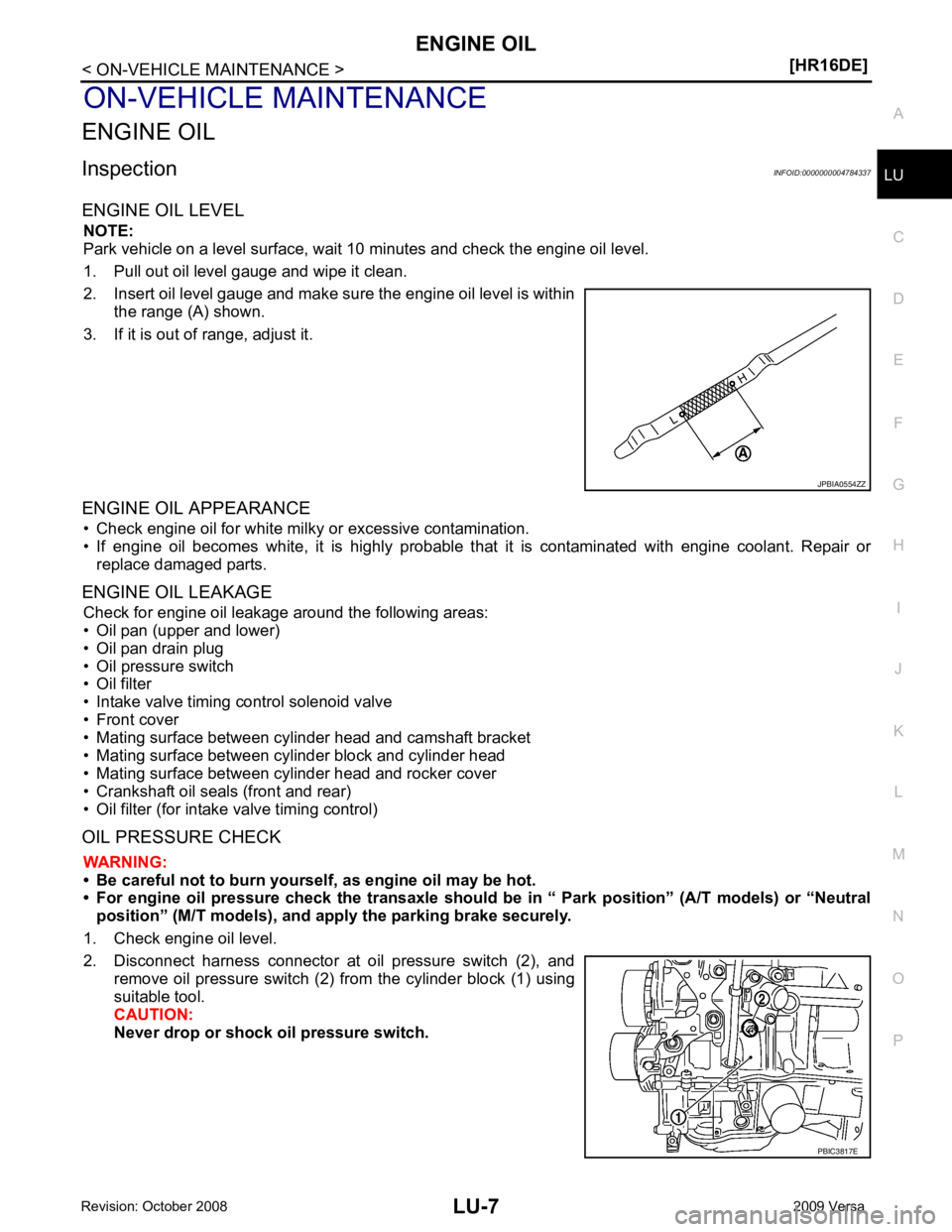
2. Insert oil level gauge and make sure the engine oil level is within the range (A) shown.
3. If it is out of range, adjust it.
ENGINE OIL APPEARANCE • Check engine oil for white milky or excessive contamination.
• If engine oil becomes white, it is highly probable t hat it is contaminated with engine coolant. Repair or
replace damaged parts.
ENGINE OIL LEAKAGE Check for engine oil leakage around the following areas:
• Oil pan (upper and lower)
• Oil pan drain plug
• Oil pressure switch
• Oil filter
• Intake valve timing control solenoid valve
• Front cover
• Mating surface between cylinder head and camshaft bracket
• Mating surface between cylinder block and cylinder head
• Mating surface between cylinder head and rocker cover
• Crankshaft oil seals (front and rear)
• Oil filter (for intake valve timing control)
OIL PRESSURE CHECK WARNING:
• Be careful not to burn yoursel f, as engine oil may be hot.
• For engine oil pressure check the transaxle should be in “ Park position” (A/T models) or “Neutral
position” (M/T models), and apply the parking brake securely.
1. Check engine oil level.
2. Disconnect harness connector at oil pressure switch (2), and remove oil pressure switch (2) from the cylinder block (1) using
suitable tool.
CAUTION:
Never drop or shock oil pressure switch. PBIC3817E