Page 1377 of 4331
EC
A
N
O P
SERVICE DATA AND SPECIFICATIONS
(SDS) .............................................................. 1534
Fuel Pressure ...................................................... 1534
Idle Speed and Ignition Timing ............................ 1534
Calculated Load Value ........................................ 1534
Mass Air Flow Sensor ......................................... 1534
Intake Air Temperature Sensor ........................... 1534
Engine Coolant Temperature Sensor .................. 1534Air Fuel Ratio (A/F) Sensor 1 Heater ...................
1535
Heated Oxygen sensor 2 Heater ......................... 1535
Crankshaft Position Sensor (POS) ...................... 1535
Camshaft Position Sensor (PHASE) ................... 1535
Throttle Control Motor .......................................... 1535
Fuel Injector ......................................................... 1535
Fuel Pump ........................................................... 1535
Page 1384 of 4331

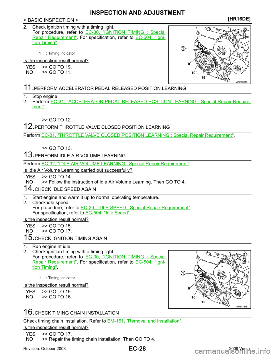
IGNITION TIMING : Special
Repair Requirement " . For specification, refer to
EC-504, " Igni-
tion Timing " .
Is the inspection result normal? YES >> GO TO 19.
NO >> GO TO 11. ACCELERATOR PEDAL RELEASED POSITION
LEARNING : Special Repair Require-ment " .
>> GO TO 12. THROTTLE VALVE CLOSED POSITION LE
ARNING : Special Repair Requirement " .
>> GO TO 13. IDLE AIR VOLUME LEARNING : Special Repair Requirement " .
Is Idle Air Volume Learning carried out successfully? YES >> GO TO 14.
NO >> Follow the instruction of Idle Air Volume Learning. Then GO TO 4. IDLE SPEED : Special Repair Requirement " .
For specification, refer to EC-504, " Idle Speed " .
Is the inspection result normal? YES >> GO TO 15.
NO >> GO TO 17. IGNITION TIMING : Special
Repair Requirement " . For specification, refer to
EC-504, " Igni-
tion Timing " .
Is the inspection result normal? YES >> GO TO 19.
NO >> GO TO 16. Removal and Installation " .
Is the inspection result normal? YES >> GO TO 17.
NO >> Repair the timing chain installation. Then GO TO 4. 1 : Timing indicator
Page 1388 of 4331

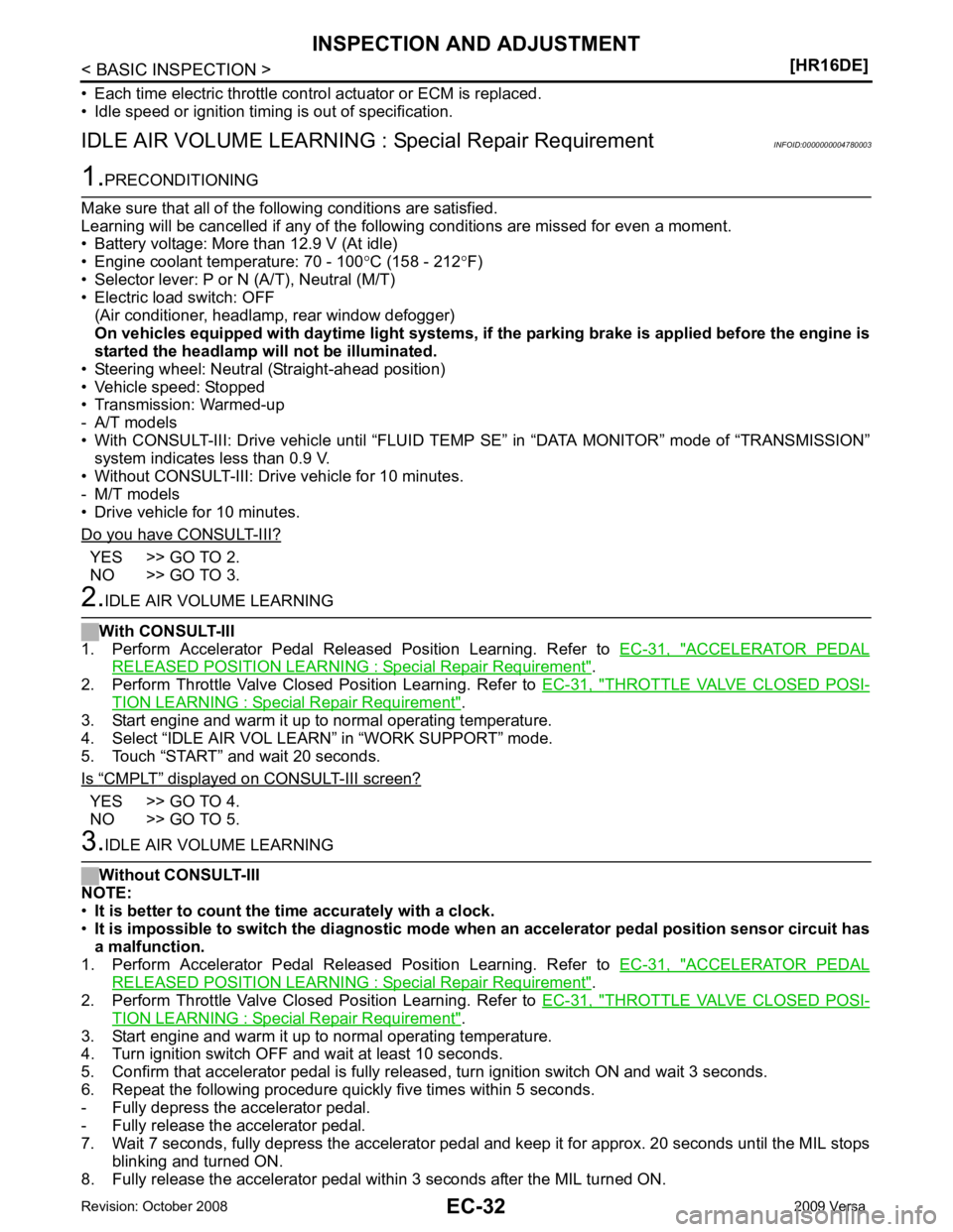
YES >> GO TO 2.
NO >> GO TO 3. ACCELERATOR PEDAL
RELEASED POSITION LEARNING : Special Repair Requirement " .
2. Perform Throttle Valve Closed Position Learning. Refer to EC-31, " THROTTLE VALVE CLOSED POSI-
TION LEARNING : Special Repair Requirement " .
3. Start engine and warm it up to normal operating temperature.
4. Select “IDLE AIR VOL LEARN” in “WORK SUPPORT” mode.
5. Touch “START” and wait 20 seconds.
Is “ CMPLT ” displayed on CONSULT-III screen?
YES >> GO TO 4.
NO >> GO TO 5. ACCELERATOR PEDAL
RELEASED POSITION LEARNING : Special Repair Requirement " .
2. Perform Throttle Valve Closed Position Learning. Refer to EC-31, " THROTTLE VALVE CLOSED POSI-
TION LEARNING : Special Repair Requirement " .
3. Start engine and warm it up to normal operating temperature.
4. Turn ignition switch OFF and wait at least 10 seconds.
5. Confirm that accelerator pedal is fully releas ed, turn ignition switch ON and wait 3 seconds.
6. Repeat the following procedure quickly five times within 5 seconds.
- Fully depress the accelerator pedal.
- Fully release the accelerator pedal.
7. Wait 7 seconds, fully depress the accelerator pedal and keep it for approx. 20 seconds until the MIL stops
blinking and turned ON.
8. Fully release the accelerator pedal within 3 seconds after the MIL turned ON.
Page 1393 of 4331
EC
NP
O
1. Mass air flow sensor
(with intake air temperature sensor) 2. Engine coolant temperature sensor 3. Electric throttle control actuator
4. Camshaft position sensor (PHASE) 5. Ignition coil (with power transistor) 6. Fuel injector
7. EVAP canister purge volume control solenoid valve
Vehicle front
Page 1397 of 4331

EC
NP
O
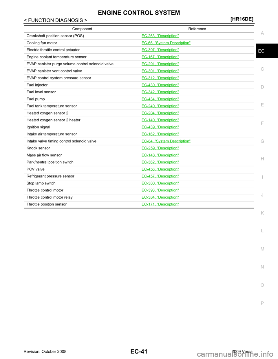
Crankshaft position sensor (POS)
EC-263, " Description "
Cooling fan motor
EC-66, " System Description "
Electric throttle control actuator
EC-397, " Description "
Engine coolant temperature sensor
EC-167, " Description "
EVAP canister purge volume control solenoid valve
EC-291, " Description "
EVAP canister vent control valve
EC-301, " Description "
EVAP control system pressure sensor
EC-312, " Description "
Fuel injector
EC-430, " Description "
Fuel level sensor
EC-342, " Description "
Fuel pump
EC-434, " Description "
Fuel tank temperature sensor
EC-240, " Description "
Heated oxygen sensor 2
EC-204, " Description "
Heated oxygen sensor 2 heater
EC-140, " Description "
Ignition signal
EC-439, " Description "
Intake air temperature sensor
EC-162, " Description "
Intake valve timing control solenoid valve
EC-84, " System Description "
Knock sensor
EC-259, " Description "
Mass air flow sensor
EC-148, " Description "
Park/neutral position switch
EC-362, " Description "
PCV valve
EC-456, " Description "
Refrigerant pressure sensor
EC-457, " Description "
Stop lamp switch
EC-380, " Description "
Throttle control motor
EC-393, " Description "
Throttle control motor relay
EC-384, " Description "
Throttle position sensor
EC-171, " Description "Component Reference
Page 1401 of 4331
MULTIPORT FUEL INJECTION SYSTEM
EC-45
< FUNCTION DIAGNOSIS >
[HR16DE] C
D E
F
G H
I
J
K L
M A EC
NP
O
Component Parts Location
INFOID:0000000004780012
1. Ignition coil (with power transistor) and spark plug 2. Intake valve timing control solenoid
valve 3. Refrigerant pressure sensor
4. Knock sensor 5. Fuel injector 6. Cooling fan motor
7. Camshaft position sensor (PHASE) 8. IPDM E/R 9. ECM
10. Mass air flow sensor (with intake air temperature sensor) 11. Engine coolant temperature sensor 12. Electric throttle control actuator
(with built in throttle position sensor
and throttle control motor)
13. EVAP canister purge volume control solenoid valve PBIB2939E
Page 1402 of 4331
EC-46< FUNCTION DIAGNOSIS >
[HR16DE]
MULTIPORT FUEL INJECTION SYSTEM
1. Mass air flow sensor (with intake air temperature sensor) 2. Engine coolant temperature sensor 3. Electric throttle control actuator
4. Camshaft position sensor (PHASE) 5. Ignition coil (with power transistor) 6. Fuel injector
7. EVAP canister purge volume control solenoid valve
Vehicle front PBIB2940E
Page 1407 of 4331
EC
NP
O
ELECTRIC IGNITION SYSTEM
System Diagram INFOID:0000000004780014
System Description INFOID:0000000004780015
INPUT/OUTPUT SIGNAL CHART
*1: This signal is sent to the ECM via the CAN communication line.
*2: ECM determines the start signal status by the signals of engine speed and battery voltage.
SYSTEM DESCRIPTION Ignition order: 1 - 3 - 4 - 2
The ignition timing is controlled by the ECM to maintain the best air-fuel ratio for every running condition of the
engine. The ignition timing data is stored in the ECM.
The ECM receives information such as the injecti on pulse width and camshaft position sensor (PHASE) sig-
nal. Computing this information, ignition si gnals are transmitted to the power transistor.
During the following conditions, the ignition timing is revi sed by the ECM according to the other data stored in
the ECM.
• At starting
• During warm-up
• At idle
• At low battery voltage
• During acceleration