Page 2445 of 4331
![NISSAN LATIO 2009 Service Repair Manual TROUBLE DIAGNOSIS
EC-1089
< SERVICE INFOMATION >
[MR TYPE 2] C
D E
F
G H
I
J
K L
M A EC
NP
O
TROUBLE DIAGNOSIS
Trouble Diagnosis Introduction INFOID:0000000004499937
INTRODUCTION The engine has an ECM NISSAN LATIO 2009 Service Repair Manual TROUBLE DIAGNOSIS
EC-1089
< SERVICE INFOMATION >
[MR TYPE 2] C
D E
F
G H
I
J
K L
M A EC
NP
O
TROUBLE DIAGNOSIS
Trouble Diagnosis Introduction INFOID:0000000004499937
INTRODUCTION The engine has an ECM](/manual-img/5/57359/w960_57359-2444.png)
TROUBLE DIAGNOSIS
EC-1089
< SERVICE INFOMATION >
[MR TYPE 2] C
D E
F
G H
I
J
K L
M A EC
NP
O
TROUBLE DIAGNOSIS
Trouble Diagnosis Introduction INFOID:0000000004499937
INTRODUCTION The engine has an ECM to control major systems such as fuel con-
trol, ignition control, idle air control system, etc. The ECM accepts
input signals from sensors and instantly drives actuators. It is essen-
tial that both input and output signals are proper and stable. At the
same time, it is important that there are no malfunctions such as vac-
uum leaks, fouled spark plugs, or other malfunctions with the engine.
It is much more difficult to diagnose an incident that occurs intermit-
tently rather than continuously. Most intermittent incidents are
caused by poor electric connections or improper wiring. In this case,
careful checking of suspected circuits may help prevent the replace-
ment of good parts.
A visual check only may not find t he cause of the incidents. A road
test with CONSULT-III (or GST) or a circuit tester connected should
be performed. Follow the Work Flow on "WORK FLOW".
Before undertaking actual checks, take a few minutes to talk with a
customer who approaches with a driv ability complaint. The customer
can supply good information about such incidents, especially inter-
mittent ones. Find out what symptoms are present and under what
conditions they occur. A Diagnosti c Worksheet like the example on
"Worksheet Sample" should be used.
Start your diagnosis by looking for conventional malfunctions first.
This will help troubleshoot drivability malfunctions on an electroni-
cally controlled engine vehicle.
WORK FLOW MEF036D
SEF233G
SEF234G
Page 2495 of 4331
POWER SUPPLY AND GROUND CIRCUIT
EC-1139
< SERVICE INFOMATION >
[MR TYPE 2] C
D E
F
G H
I
J
K L
M A EC
NP
O
POWER SUPPLY AND GROUND CIRCUIT
Wiring Diagram INFOID:0000000004499955
Specification data are reference values and are measured between each terminal and ground.
CAUTION:
Do not use ECM ground terminals wh en measuring input/output voltage. Doing so may result in dam-
age to the ECM's transistor. Use a ground ot her than ECM terminals, such as the ground. BBWA2625E
Page 2497 of 4331
![NISSAN LATIO 2009 Service Repair Manual POWER SUPPLY AND GROUND CIRCUIT
EC-1141
< SERVICE INFOMATION >
[MR TYPE 2] C
D E
F
G H
I
J
K L
M A EC
NP
O
OK or NG OK >> GO TO 5.
NG >> Repair or replace ground connections. 5.
CHECK ECM GROUND CIRCU NISSAN LATIO 2009 Service Repair Manual POWER SUPPLY AND GROUND CIRCUIT
EC-1141
< SERVICE INFOMATION >
[MR TYPE 2] C
D E
F
G H
I
J
K L
M A EC
NP
O
OK or NG OK >> GO TO 5.
NG >> Repair or replace ground connections. 5.
CHECK ECM GROUND CIRCU](/manual-img/5/57359/w960_57359-2496.png)
POWER SUPPLY AND GROUND CIRCUIT
EC-1141
< SERVICE INFOMATION >
[MR TYPE 2] C
D E
F
G H
I
J
K L
M A EC
NP
O
OK or NG OK >> GO TO 5.
NG >> Repair or replace ground connections. 5.
CHECK ECM GROUND CIRCUIT FOR OPEN AND SHORT-I
1. Disconnect ECM harness connector.
2. Check harness continuity between ECM terminals 10, 11, 108 and ground.
Refer to Wiring Diagram.
3. Also check harness for short to power.
OK or NG OK >> GO TO 7.
NG >> GO TO 6. 6.
DETECT MALFUNCTIONING PART
Check the following.
• Harness connectors F8, E8
• Harness for open or short between ECM and ground
>> Repair open circuit or short to power in harness or connectors. 7.
CHECK ECM POWER SUPPLY CIRCUIT-II
1. Reconnect ECM harness connector.
2. Turn ignition switch ON.
3. Check voltage between IPDM E/R terminal 3 and ground with
CONSULT-III or tester.
OK or NG OK >> Go to
EC-1518 .
NG >> GO TO 8. 8.
CHECK ECM POWER SUPPLY CIRCUIT-III
1. Turn ignition switch OFF and wait at least 10 seconds.
2. Turn ignition switch ON and then OFF. :
Vehicle front
1. Body ground E24 2. Engine ground F9 3. Engine ground F16
4. Body ground E15 BBIA0698E
Continuity should exist.
Voltage: Battery voltage PBIB2658E
Page 2498 of 4331
![NISSAN LATIO 2009 Service Repair Manual EC-1142< SERVICE INFOMATION >
[MR TYPE 2]
POWER SUPPLY AND GROUND CIRCUIT
3. Check voltage between ECM terminal 105 and ground with CONSULT-III or tester.
OK or NG OK >> GO TO 14.
NG (Battery NISSAN LATIO 2009 Service Repair Manual EC-1142< SERVICE INFOMATION >
[MR TYPE 2]
POWER SUPPLY AND GROUND CIRCUIT
3. Check voltage between ECM terminal 105 and ground with CONSULT-III or tester.
OK or NG OK >> GO TO 14.
NG (Battery](/manual-img/5/57359/w960_57359-2497.png)
EC-1142< SERVICE INFOMATION >
[MR TYPE 2]
POWER SUPPLY AND GROUND CIRCUIT
3. Check voltage between ECM terminal 105 and ground with CONSULT-III or tester.
OK or NG OK >> GO TO 14.
NG (Battery voltage does not exist.)>>GO TO 9.
NG (Battery voltage exists for more than a few seconds.)>>GO TO 11. 9.
CHECK ECM POWER SUPPLY CIRCUIT-IV
1. Turn ignition switch OFF and wait at least 10 seconds.
2. Check voltage between ECM terminal 32 and ground with CON-
SULT-III or tester.
OK or NG OK >> GO TO 10.
NG >> GO TO 11. 10.
CHECK ECM POWER SUPPLY CIRCUIT-V
1. Disconnect ECM harness connector.
2. Disconnect IPDM E/R harness connector E43.
3. Check harness continuity between ECM terminal 105 and IPDM E/R terminal 4.
Refer to Wiring Diagram.
4. Also check harness for short to ground and short to power.
OK or NG OK >> GO TO 17.
NG >> Repair open circuit or short to ground or short to power in harness or connectors. 11.
CHECK ECM POWER SUPPLY CIRCUIT-VI
1. Disconnect ECM harness connector.
2. Disconnect IPDM E/R harness connector E43.
3. Check harness continuity between ECM terminal 32 and IPDM E/R terminal 7.
Refer to Wiring Diagram.
4. Also check harness for short to ground and short to power.
OK or NG OK >> GO TO 13.
NG >> GO TO 12. 12.
DETECT MALFUNCTIONING PART
Check the following.
• Harness connectors E8, F8
• Harness for open or short between ECM and IPDM E/R
>> Repair open circuit or short to ground or short to power in harness or connectors.
Voltage: After turning ignition switch OFF, battery
voltage will exist for a few seconds, then drop
approximately 0V. PBIB3037E
Voltage: Battery voltage
PBIA9562J
Continuity should exist.
Continuity should exist.
Page 2499 of 4331
![NISSAN LATIO 2009 Service Repair Manual POWER SUPPLY AND GROUND CIRCUIT
EC-1143
< SERVICE INFOMATION >
[MR TYPE 2] C
D E
F
G H
I
J
K L
M A EC
NP
O 13.
CHECK 20A FUSE
1. Disconnect 20A fuse from IPDM E/R.
2. Check 20A fuse.
OK or NG OK >> GO NISSAN LATIO 2009 Service Repair Manual POWER SUPPLY AND GROUND CIRCUIT
EC-1143
< SERVICE INFOMATION >
[MR TYPE 2] C
D E
F
G H
I
J
K L
M A EC
NP
O 13.
CHECK 20A FUSE
1. Disconnect 20A fuse from IPDM E/R.
2. Check 20A fuse.
OK or NG OK >> GO](/manual-img/5/57359/w960_57359-2498.png)
POWER SUPPLY AND GROUND CIRCUIT
EC-1143
< SERVICE INFOMATION >
[MR TYPE 2] C
D E
F
G H
I
J
K L
M A EC
NP
O 13.
CHECK 20A FUSE
1. Disconnect 20A fuse from IPDM E/R.
2. Check 20A fuse.
OK or NG OK >> GO TO 17.
NG >> Replace 20A fuse. 14.
CHECK GROUND CONNECTIONS
1. Loosen and retighten ground screw on the body. Refer to EC-1144, " Ground Inspection " .
OK or NG OK >> GO TO 15.
NG >> Repair or replace ground connections. 15.
CHECK ECM GROUND CIRCUIT FOR OPEN AND SHORT-II
1. Disconnect ECM harness connector.
2. Check harness continuity between ECM terminals 10, 11, 108 and ground.
Refer to Wiring Diagram.
3. Also check harness for short to power.
OK or NG OK >> GO TO 17.
NG >> GO TO 16. 16.
DETECT MALFUNCTIONING PART
Check the following.
• Harness connectors F8, E8
• Harness for open or short between ECM and ground
>> Repair open circuit or short to power in harness or connectors. 17.
CHECK INTERMITTENT INCIDENT
Refer to EC-1138 .
OK or NG OK >> Replace IPDM E/R. Refer to
PG-27, " Removal and Installation of IPDM E/R " .
NG >> Repair open circuit or short to power in harness or connectors. :
Vehicle front
1. Body ground E24 2. Engine ground F9 3. Engine ground F16
4. Body ground E15 BBIA0698E
Continuity should exist.
Page 2501 of 4331

EC
NP
O
DTC U0101 CAN COMMUNICATION LINE
Description INFOID:0000000004306003
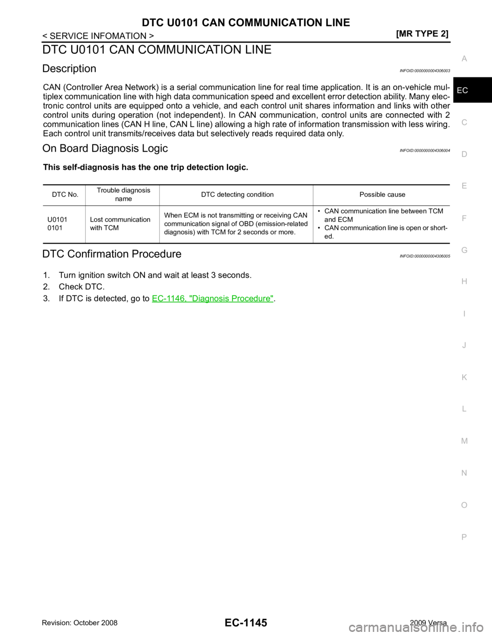
CAN (Controller Area Network) is a serial communication li ne for real time application. It is an on-vehicle mul-
tiplex communication line with high data communication speed and excellent error detection ability. Many elec-
tronic control units are equipped onto a vehicle, and each control unit shares information and links with other
control units during operation (not independent). In CAN communication, control units are connected with 2
communication lines (CAN H line, CAN L line) allowing a high rate of information transmission with less wiring.
Each control unit transmits/receives data but selectively reads required data only.
On Board Diagnosis Logic INFOID:0000000004306004
This self-diagnosis has the on e trip detection logic.
DTC Confirmation Procedure INFOID:0000000004306005
1. Turn ignition switch ON and wait at least 3 seconds.
2. Check DTC.
3. If DTC is detected, go to EC-1146, " Diagnosis Procedure " .
DTC No.
Trouble diagnosis
name DTC detecting condition Possible cause
U0101
0101 Lost communication
with TCM When ECM is not transmitting or receiving CAN
communication signal of OBD (emission-related
diagnosis) with TCM for 2 seconds or more. • CAN communication line between TCM
and ECM
• CAN communication line is open or short-
ed.
Page 2502 of 4331
EC-1146< SERVICE INFOMATION >
[MR TYPE 2]
DTC U0101 CAN COMMUNICATION LINE
Wiring Diagram INFOID:0000000004306006
Diagnosis Procedure INFOID:0000000004306007
Go to LAN-26, " CAN System Specification Chart " . BBWA2626E
Page 2503 of 4331

EC
NP
O
DTC U0140 CAN COMMUNICATION LINE
Description INFOID:0000000004477023
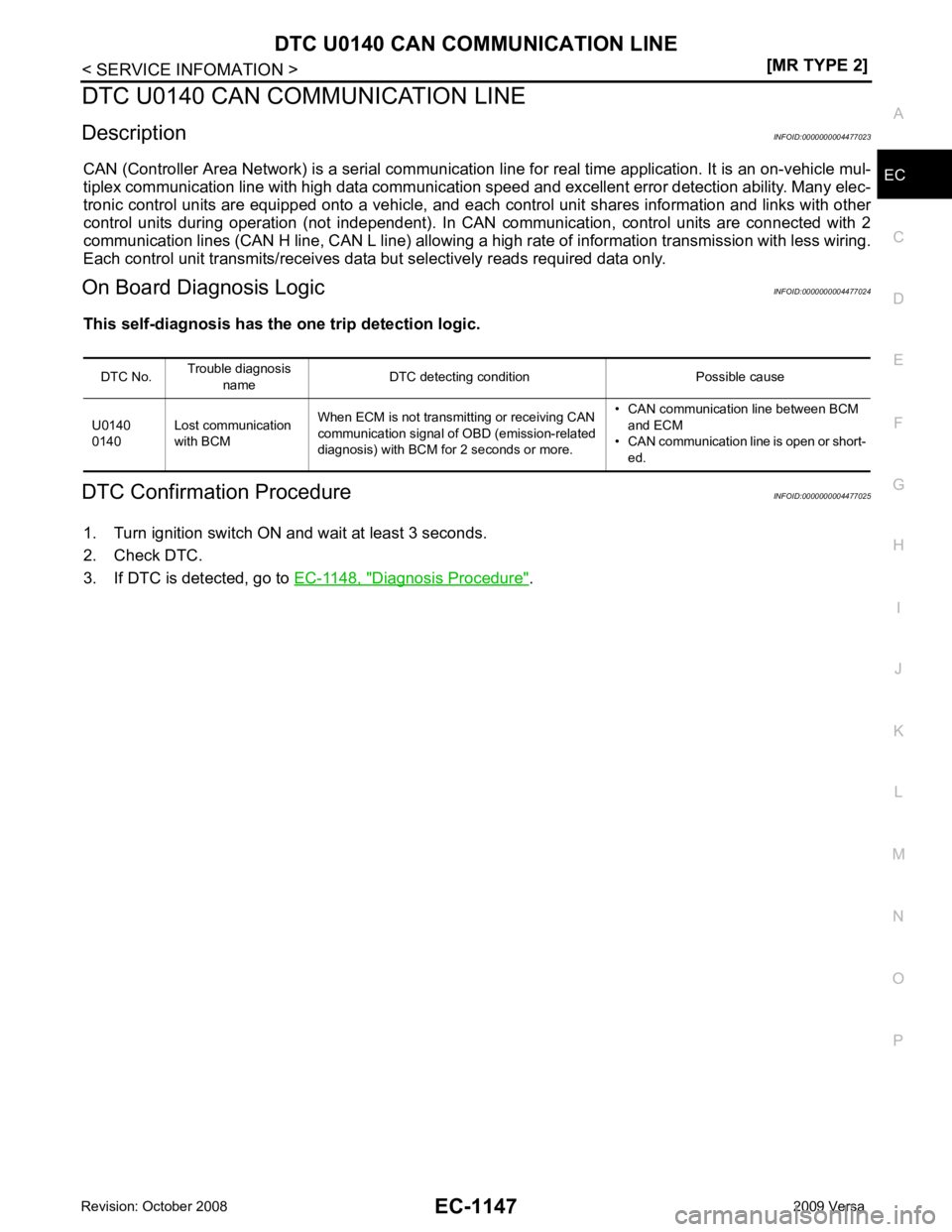
CAN (Controller Area Network) is a serial communication li ne for real time application. It is an on-vehicle mul-
tiplex communication line with high data communication speed and excellent error detection ability. Many elec-
tronic control units are equipped onto a vehicle, and each control unit shares information and links with other
control units during operation (not independent). In CAN communication, control units are connected with 2
communication lines (CAN H line, CAN L line) allowing a high rate of information transmission with less wiring.
Each control unit transmits/receives data but selectively reads required data only.
On Board Diagnosis Logic INFOID:0000000004477024
This self-diagnosis has the on e trip detection logic.
DTC Confirmation Procedure INFOID:0000000004477025
1. Turn ignition switch ON and wait at least 3 seconds.
2. Check DTC.
3. If DTC is detected, go to EC-1148, " Diagnosis Procedure " .
DTC No.
Trouble diagnosis
name DTC detecting condition Possible cause
U0140
0140 Lost communication
with BCM When ECM is not transmitting or receiving CAN
communication signal of OBD (emission-related
diagnosis) with BCM for 2 seconds or more. • CAN communication line between BCM
and ECM
• CAN communication line is open or short-
ed.