Page 3790 of 4331

CHASSIS AND BODY MAINTENANCE
MA-47
< SERVICE INFORMATION >
C
D E
F
G H
I
J
K
M A
B MA
N
O P
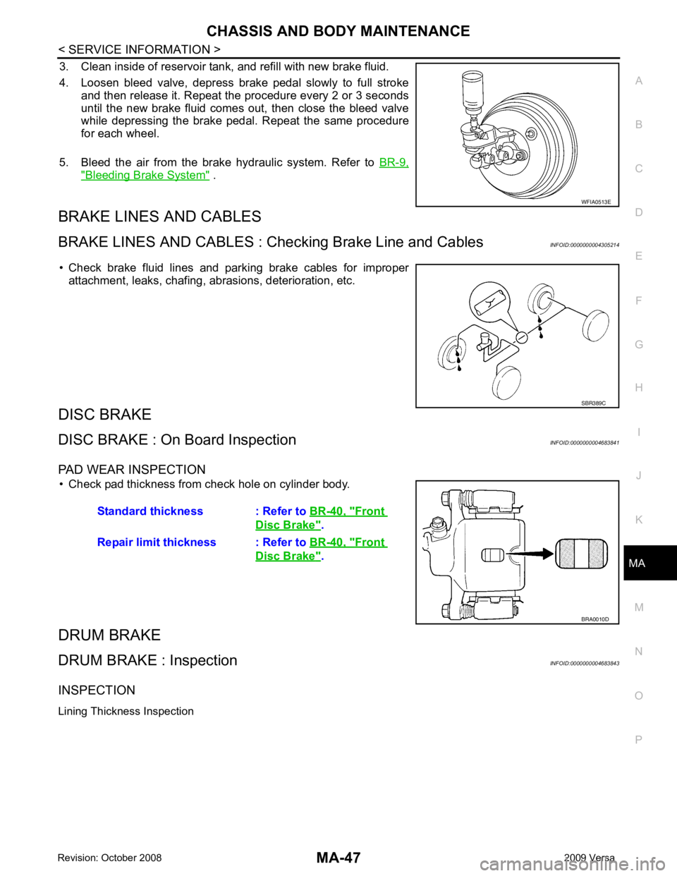
3. Clean inside of reservoir tank, and refill with new brake fluid.
4. Loosen bleed valve, depress brake pedal slowly to full stroke and then release it. Repeat the procedure every 2 or 3 seconds
until the new brake fluid comes out, then close the bleed valve
while depressing the brake pedal . Repeat the same procedure
for each wheel.
5. Bleed the air from the brake hydraulic system. Refer to BR-9," Bleeding Brake System " .
BRAKE LINES AND CABLES
BRAKE LINES AND CABLES : C hecking Brake Line and Cables INFOID:0000000004305214
• Check brake fluid lines and parking brake cables for improper attachment, leaks, chafing, abrasions, deterioration, etc.
DISC BRAKE
DISC BRAKE : On Board Inspection INFOID:0000000004683841
PAD WEAR INSPECTION • Check pad thickness from check hole on cylinder body.
DRUM BRAKE
DRUM BRAKE : Inspection INFOID:0000000004683843
INSPECTION
Lining Thickness Inspection WFIA0513E
SBR389C
Standard thickness : Refer to
BR-40, " Front
Disc Brake " .
Repair limit thickness : Refer to BR-40, " Front
Disc Brake " .
BRA0010D
Page 3811 of 4331

MT
N
O P
Installation is in the reverse order of removal.
CAUTION:
• Make sure the transaxle assembly does not interfer e with the wire harnesses and clutch tube.
• When installing transaxle assembly, do not bring input shaft into contact with clutch cover.
• If transaxle is removed from the vehicle, always replace CSC. Refer to CL-12, " Removal and Installa-
tion " .
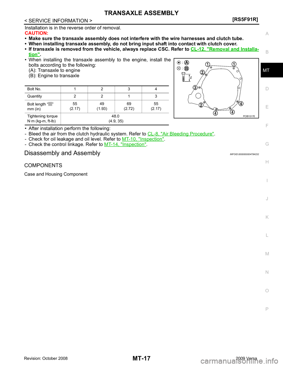
• When installing the transaxle assembly to the engine, install the bolts according to the following:
(A): Transaxle to engine
(B): Engine to transaxle
• After installation perform the following:
- Bleed the air from the clutch hydraulic system. Refer to CL-8, " Air Bleeding Procedure " .
- Check for oil leakage and oil level. Refer to MT-10, " Inspection " .
- Check the control linkage. Refer to MT-14, " Inspection " .
Disassembly and Assembly INFOID:0000000004784232
COMPONENTS
Case and Housing Component Bolt No. 1 2 3 4
Quantity 2 2 1 3
Bolt length “ ”
mm (in) 55
(2.17) 49
(1.93) 69
(2.72) 55
(2.17)
Tightening torque
N·m (kg-m, ft-lb) 48.0
(4.9, 35)
Page 3853 of 4331
MT
N
O P
Installation is in the reverse order of removal.
CAUTION:
When installing transaxle assembly, be careful not to bring transaxle input shaft into contact with
clutch cover.
• If transaxle is removed from the v ehicle, always replace CSC. Refer to CL-12, " Removal and Installation " .
• When installing the transaxle assembly to the engine, install the
bolts as shown.
A: M/T to engine
B: Engine to M/T
• After installation, bleed the air from the clutch hydraulic system. Refer to CL-8, " Air Bleeding Procedure " .
• After installation, check oil level, and check for leaks and loose mechanisms. Refer to MT-52, " Checking M/T
Oil " .
Disassembly and Assembly INFOID:0000000004305279
COMPONENTS
Case and Housing Components Bolt No. 1 2
Quantity 3 6
Bolt length “ ” mm (in) 60 (2.36) 50 (1.97)
Tightening torque
N·m (kg-m, ft-lb) 62.0 (6.3, 46)
Page 4123 of 4331

On-
Vehicle Service " .
3. Remove wheel sensor and wheel sensor harness from wheel hub and bearing assembly and rear suspen-
sion beam. Refer to BRC-32, " Removal and Installation " .
4. Remove lock plate and separate brake tube from brake hose. Refer to BR-12, " Rear Brake Tube and Hose " .
5. Remove wheel hub and bearing assembly and back plate. Refer to RAX-5, " On-Vehicle Inspection and Service " .
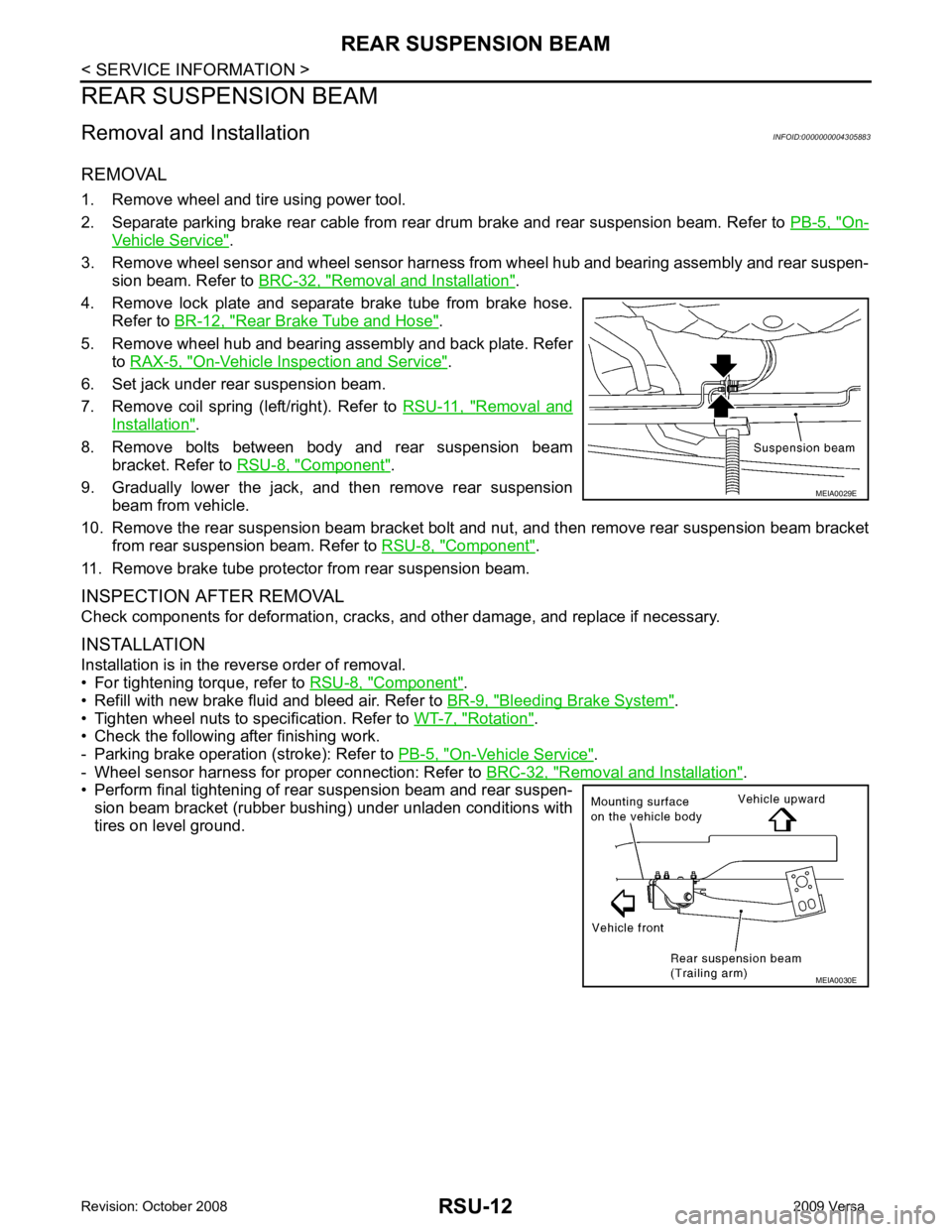
6. Set jack under rear suspension beam.
7. Remove coil spring (left/right). Refer to RSU-11, " Removal and
Installation " .
8. Remove bolts between body and rear suspension beam bracket. Refer to RSU-8, " Component " .
9. Gradually lower the jack, and then remove rear suspension beam from vehicle.
10. Remove the rear suspension beam bracket bolt and nut, and then remove rear suspension beam bracket
from rear suspension beam. Refer to RSU-8, " Component " .
11. Remove brake tube protector from rear suspension beam.
INSPECTION AFTER REMOVAL
Check components for deformation, cracks, and other damage, and replace if necessary.
INSTALLATION
Installation is in the reverse order of removal.
• For tightening torque, refer to RSU-8, " Component " .
• Refill with new brake fluid and bleed air. Refer to BR-9, " Bleeding Brake System " .
• Tighten wheel nuts to specification. Refer to WT-7, " Rotation " .
• Check the following after finishing work.
- Parking brake operation (stroke): Refer to PB-5, " On-Vehicle Service " .
- Wheel sensor harness for proper connection: Refer to BRC-32, " Removal and Installation " .
• Perform final tightening of rear suspension beam and rear suspen-
sion beam bracket (rubber bushing) under unladen conditions with
tires on level ground. MEIA0030E
Page:
< prev 1-8 9-16 17-24