2009 NISSAN LATIO steering wheel
[x] Cancel search: steering wheelPage 434 of 4331
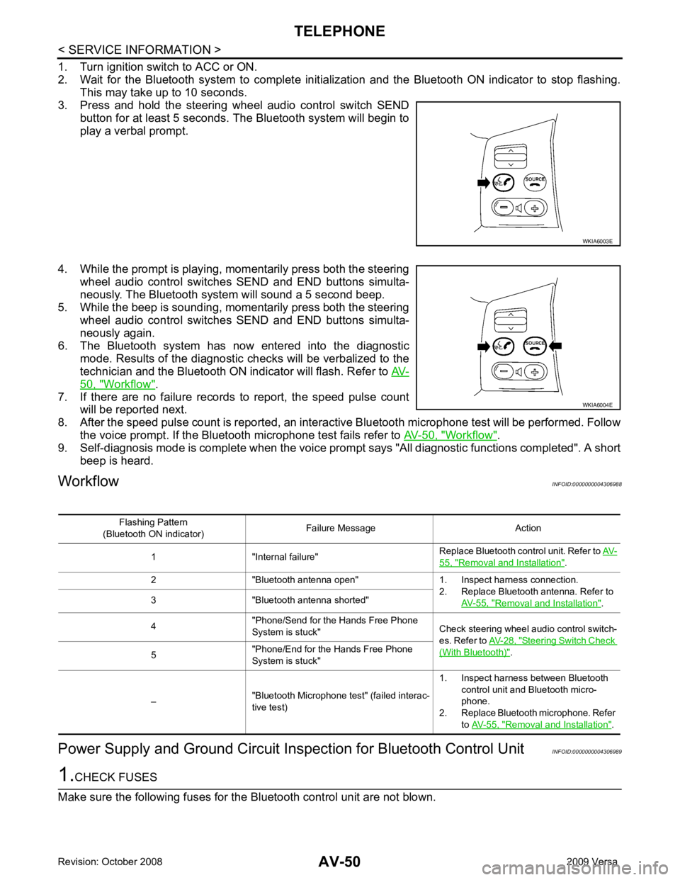
50, " Workflow " .
7. If there are no failure records to report, the speed pulse count will be reported next.
8. After the speed pulse count is reported, an intera ctive Bluetooth microphone test will be performed. Follow
the voice prompt. If the Bluetooth microphone test fails refer to AV-50, " Workflow " .
9. Self-diagnosis mode is complete when the voice prom pt says "All diagnostic functions completed". A short
beep is heard.
Workflow INFOID:0000000004306988
Power Supply and Ground Circuit Ins pection for Bluetooth Control Unit INFOID:0000000004306989 WKIA6004E
55, " Removal and Installation " .
2 "Bluetooth antenna open" 1. Inspect harness connection. 2. Replace Bluetooth antenna. Refer to AV-55, " Removal and Installation " .
3 "Bluetooth antenna shorted"
4 "Phone/Send for the Hands Free Phone
System is stuck" Check steering wheel audio control switch-
es. Refer to AV-28, " Steering Switch Check
(With Bluetooth) " .
5 "Phone/End for the Hands Free Phone
System is stuck"
– "Bluetooth Microphone test" (failed interac-
tive test) 1. Inspect harness between Bluetooth
control unit and Bluetooth micro-
phone.
2. Replace Bluetooth microphone. Refer to AV-55, " Removal and Installation " .
Page 436 of 4331
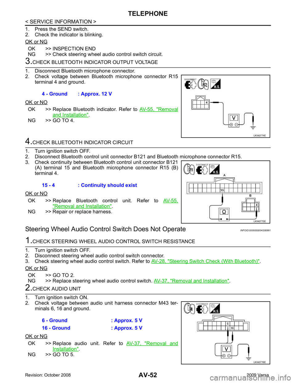
OK >> INSPECTION END
NG >> Check steering wheel audio control switch circuit. OK >> Replace Bluetooth indicator. Refer to
AV-55, " Removal
and Installation " .
NG >> GO TO 4. OK >> Replace Bluetooth control unit. Refer to
AV-55," Removal and Installation " .
NG >> Repair or replace harness.
Steering Wheel Audio Control Switch Does Not Operate INFOID:0000000004306991 Steering Switch Check (With Bluetooth) " .
OK or NG OK >> GO TO 2.
NG >> Replace steering wheel audio control switch. AV-37, " Removal and Installation " .
OK >> Replace audio unit. Refer to
AV-37, " Removal and
Installation " .
NG >> GO TO 5. 4 - Ground : Approx. 12 V
Page 437 of 4331
AV
N
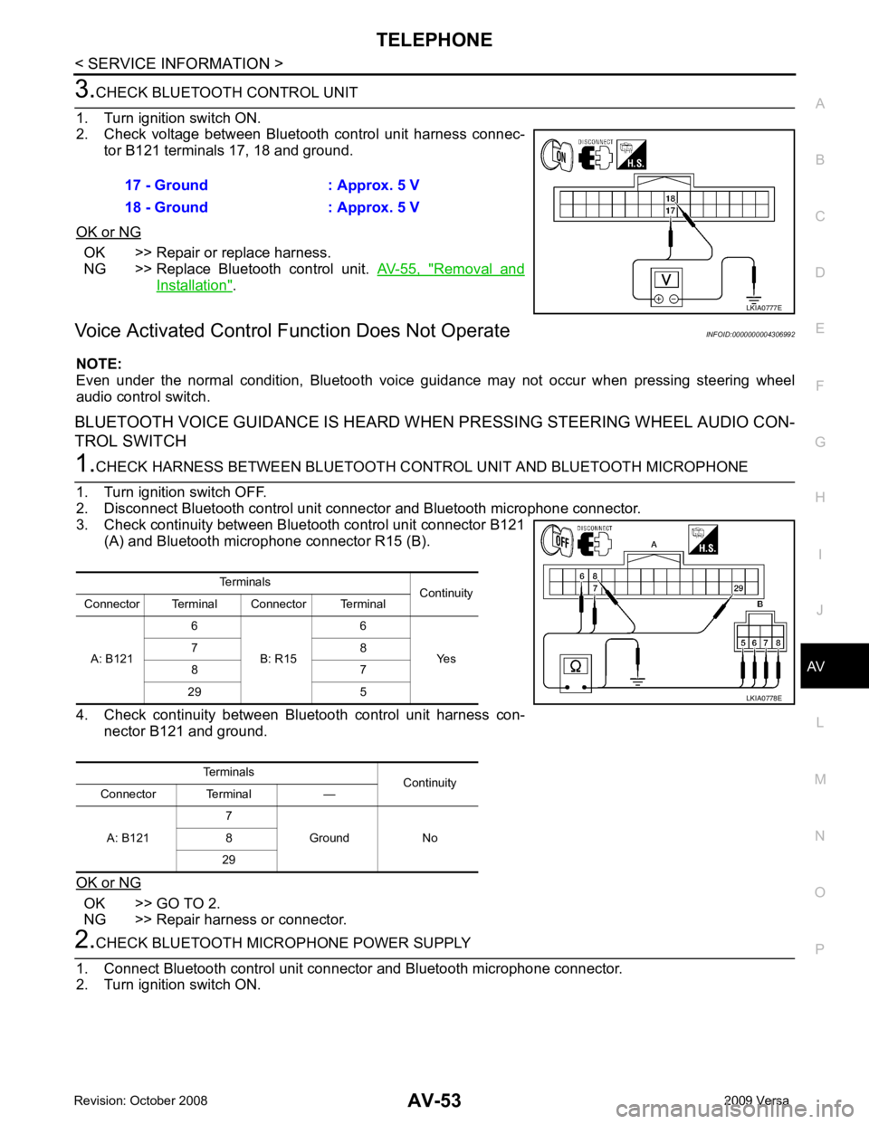
O P OK >> Repair or replace harness.
NG >> Replace Bluetooth control unit. AV-55, " Removal and
Installation " .
Voice Activated Control F unction Does Not Operate INFOID:0000000004306992
NOTE:
Even under the normal condition, Bluetooth voice guidance may not occur when pressing steering wheel
audio control switch.
BLUETOOTH VOICE GUIDANCE IS HEARD WHEN PRESSING STEERING WHEEL AUDIO CON-
TROL SWITCH OK >> GO TO 2.
NG >> Repair harness or connector.
Page 438 of 4331
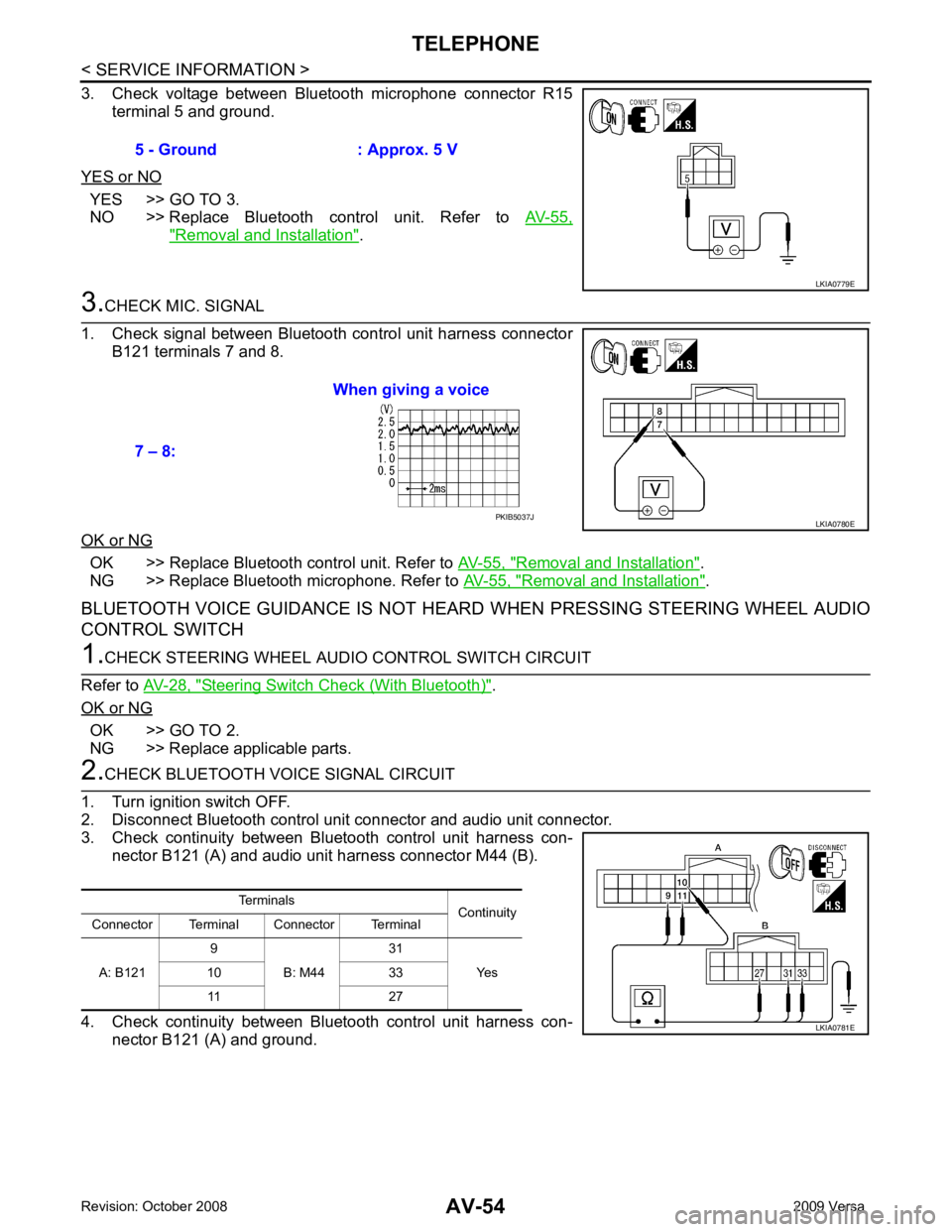
YES >> GO TO 3.
NO >> Replace Bluetooth control unit. Refer to AV-55," Removal and Installation " .
OK >> Replace Bluetooth control unit. Refer to
AV-55, " Removal and Installation " .
NG >> Replace Bluetooth microphone. Refer to AV-55, " Removal and Installation " .
BLUETOOTH VOICE GUIDANCE IS NOT HEARD WHEN PRESSING STEERING WHEEL AUDIO
CONTROL SWITCH Steering Switch Check (With Bluetooth) " .
OK or NG OK >> GO TO 2.
NG >> Replace applicable parts. PKIB5037J
Terminals Continuity
Connector Terminal Connector Terminal
A: B121 9
B: M44 31
Yes
10 33
11 27
Page 462 of 4331

BL
N
O P
CONTENTS
BODY, LOCK & SECURITY SYSTEM
SERVICE INFORMATION .. ..........................4
PRECAUTIONS .............................................. .....4
Precaution for Supplemental Restraint System
(SRS) "AIR BAG" and "SEAT BELT PRE-TEN-
SIONER" ............................................................. ......
4
Precaution Necessary fo r Steering Wheel Rota-
tion After Battery Disconnect ............................... ......
4
Precaution for Procedure without Cowl Top Cover ......5
Precaution for Work ............................................ ......5
PREPARATION .............................................. .....6
Special Service Tool ........................................... ......6
Commercial Service Tool .................................... ......6
SQUEAK AND RATTLE TROUBLE DIAG-
NOSES ........................ ........................................7
Work Flow ........................................................... ......7
Generic Squeak and Rattle Troubleshooting ...... ......9
Diagnostic Worksheet ......................................... ....11
HOOD ............................................................. ....13
Fitting Adjustment ............................................... ....13
Removal and Installation .........................................14
Removal and Installation of Hood Lock Control .. ....15
Hood Lock Control Inspec tion .................................17
RADIATOR CORE SUPPORT ....................... ....19
Removal and Installation .........................................19
FRONT FENDER ............................................ ....21
Removal and Installation .........................................21
POWER DOOR LOCK SYSTEM .................... ....22
Component Parts and Harness Connector Loca-
tion ...................................................................... ....
22
System Description ............................................. ....23
CAN Communication System Description ........... ....25
Schematic ........................................................... ....26
Wiring Diagram - D/LOCK - ................................. ....27
Schematic ........................................................... ....31
Wiring Diagram - D/LOCK - ................................. ....32 Terminal and Reference
Value for BCM ..................37
Work Flow ............................................................ ....41
CONSULT-III Function (B CM) .................................41
Trouble Diagnosis Symptom Chart ...................... ....43
BCM Power Supply and Ground Circuit Inspection ....43
Door Switch Check (Hatchback) .......................... ....44
Door Switch Check (Sedan) ................................ ....47
Key Switch (Insert) Check ................................... ....48
Door Lock and Unlock Switch Check .................. ....49
Front Door Lock Assembly LH (Actuator) Check .....52
Door Lock Actuator Check (Front RH and Rear
LH/RH) ................................................................. ....
53
Front Door Key Cylinder S witch LH Check ..............54
Passenger Select Unlock Relay Circuit Inspection
(With Intelligent Key) ........................................... ....
55
REMOTE KEYLESS ENTRY SYSTEM ............. 58
Component Parts and Harness Connector Loca-
tion ....................................................................... ....
58
System Description .............................................. ....58
CAN Communication System Description ........... ....60
Schematic ............................................................ ....61
Wiring Diagram - KEYLES - ................................ ....62
Terminal and Reference Value for BCM ..................65
How to Perform Trouble Diagnosis ...................... ....69
Preliminary Check ............................................... ....69
CONSULT-III Function (B CM) .................................69
Work Flow ............................................................ ....71
Trouble Diagnosis Symptom Chart ...................... ....71
Keyfob Battery and Function Check .................... ....72
ACC Switch Check .............................................. ....74
Door Switch Check (Hatchback) .......................... ....74
Door Switch Check (Sedan) ................................ ....76
Key Switch (Insert) Check ................................... ....78
Hazard Function Check ....................................... ....78
Horn Function Check ........................................... ....79
Interior Lamp and Ignition Keyhole Illumination
Function Check .................................................... ....
79
Remote Keyless Entry Rece iver Check ...................80
Keyfob Function (Lock) Check ............................ ....82
Page 801 of 4331

BR
N
O P
CONTENTS
BRAKE SYSTEM
SERVICE INFORMATION .. ..........................2
PRECAUTIONS .............................................. .....2
Precaution for Supplemental Restraint System
(SRS) "AIR BAG" and "SEAT BELT PRE-TEN-
SIONER" ............................................................. ......
2
Precaution Necessary fo r Steering Wheel Rota-
tion After Battery Disconnect ............................... ......
2
Precaution for Brake System .............................. ......3
PREPARATION .............................................. .....4
Special Service Tool ........................................... ......4
Commercial Service Tool .................................... ......4
NOISE, VIBRATION AND HARSHNESS
(NVH) TROUBLESHOOTING ........................ .....5
NVH Troubleshooting Chart ................................ ......5
BRAKE PEDAL .............................................. .....6
Inspection and Adjustment .................................. ......6
Removal and Installation ...........................................7
BRAKE FLUID .....................................................9
On Board Inspection ........................................... ......9
Drain and Refill .................................................... ......9
Bleeding Brake System ....................................... ......9
BRAKE TUBE AND HOSE ............................ ....11
Hydraulic Circuit .................................................. ....11
Front Brake Tube and Hose ................................ ....12
Rear Brake Tube and Hose ................................ ....12
Inspection After Installation ................................. ....13
DUAL PROPORTIONING VALVE ................. ....14
Removal and Installation .........................................14
Inspection ............................................................ ....14
BRAKE MASTER CY LINDER ........................ ....15
On-Board Inspection ........................................... ....15 Removal and Installation .....................................
....15
Disassembly and Assembly ................................. ....16
BRAKE BOOSTER ........................................... 20
On Board Inspection ............................................ ....20
Removal and Installation ..................................... ....21
VACUUM LINES ............................................... 23
Component .......................................................... ....23
Removal and Installation ..................................... ....23
Inspection ............................................................ ....23
FRONT DISC BRAKE ....................................... 25
On Board Inspection ............................................ ....25
Component .......................................................... ....25
Removal and Installation of Brake Pad ...................26
Removal and Installation of Brake Caliper Assem-
bly ........................................................................ ....
28
Disassembly and Assembly of Brake Caliper As-
sembly ................................................................. ....
29
Brake Burnishing Procedure ................................ ....32
REAR DRUM B RAKE ....................................... 33
Component .......................................................... ....33
Removal and Installation of Drum Brake Assembly ....34
Removal and Installation of Wheel Cylinder ........ ....37
Disassembly and Assembly of Wheel Cylinder ... ....37
SERVICE DATA AND SPECIFICATIONS
(SDS) ................................................................. 38
General Specification .......................................... ....38
Brake Pedal ......................................................... ....39
Check Valve ........................................................ ....39
Brake Booster ...................................................... ....40
Front Disc Brake .................................................. ....40
Rear Drum Brake ................................................. ....40
Page 803 of 4331
BR
N
O P
5. When the repair work is completed, return the ignition switch to the
″LOCK ″ position before connecting
the battery cables. (At this time, the steering lock mechanism will engage.)
6. Perform a self-diagnosis check of al l control units using CONSULT-III.
Precaution for Brake System INFOID:0000000004305887
• Refill using recommended brake fluid. Refer to MA-14 .
• Never reuse drained brake fluid.
• Be careful not to splash brake fluid on painted surfac e of body. If brake fluid is splashed on painted surfaces
of body immediately wipe it off with cloth and then wash it away with water.
• To clean or wash all parts of master cylinder, disc brake caliper and wheel cylinder, use new brake fluid.
• Never use mineral oils such as gasoline or kerosene. They will ruin rubber parts of the hydraulic system.
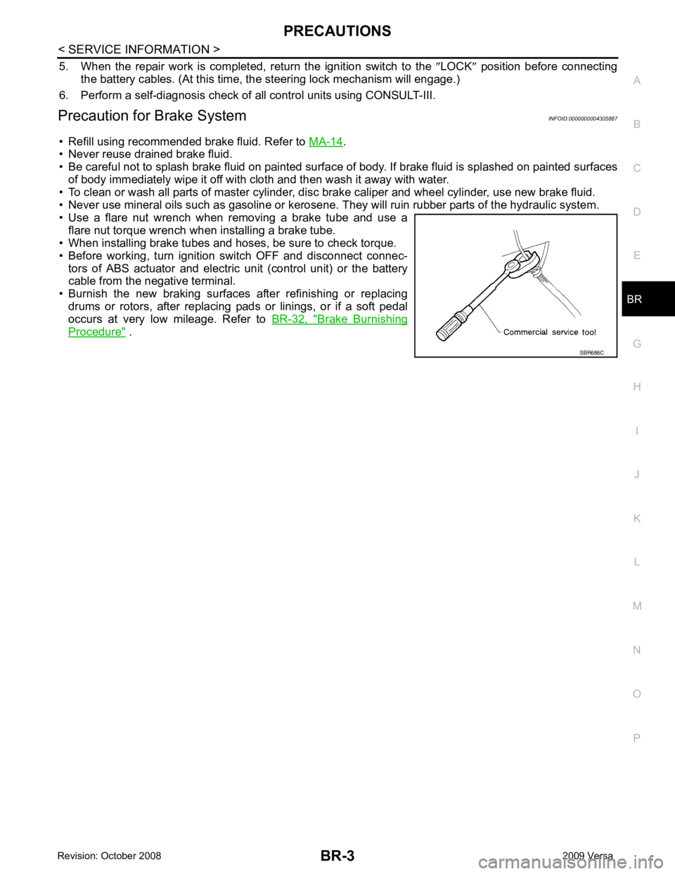
• Use a flare nut wrench when removing a brake tube and use a flare nut torque wrench when installing a brake tube.
• When installing brake tubes and hoses, be sure to check torque.
• Before working, turn igniti on switch OFF and disconnect connec-
tors of ABS actuator and electric unit (control unit) or the battery
cable from the negative terminal.
• Burnish the new braking surfaces after refinishing or replacing drums or rotors, after replacing p ads or linings, or if a soft pedal
occurs at very low mileage. Refer to BR-32, " Brake Burnishing
Procedure " .
Page 805 of 4331
BR
N
O P
NOISE, VIBRATION AND HARSHN
ESS (NVH) TROUBLESHOOTING
NVH Troubleshooting Chart INFOID:0000000004305889
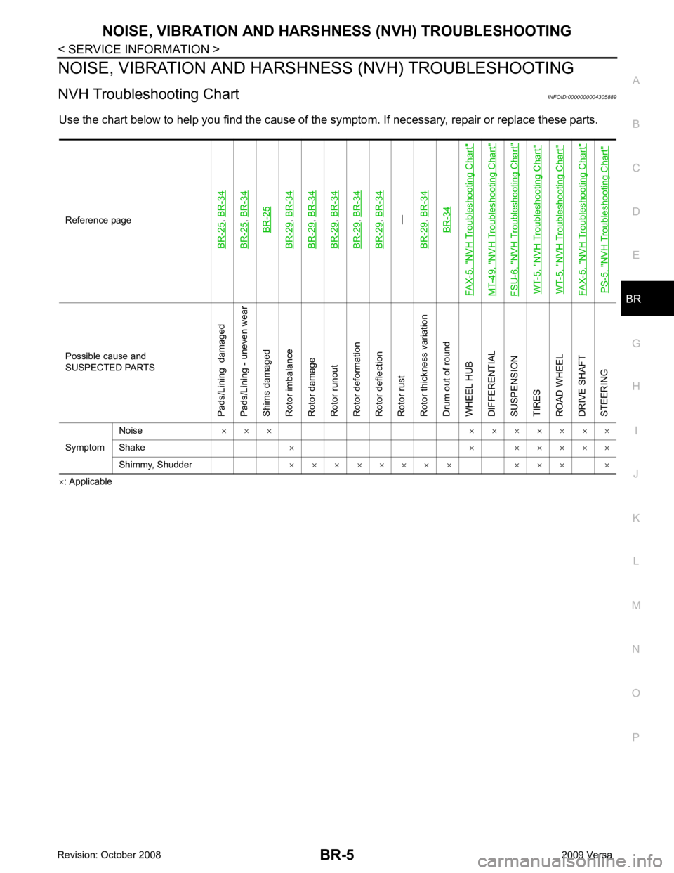
Use the chart below to help you find t he cause of the symptom. If necessary, repair or replace these parts.
× : ApplicableReference pageBR-25
,
BR-34
BR-25
, BR-34BR-25
BR-29
, BR-34
BR-29
, BR-34
BR-29
, BR-34
BR-29
, BR-34
BR-29
, BR-34—
BR-29, BR-34BR-34
FAX-5, "
NVH Troubleshooting Chart
"
MT-49, "
NVH Troubleshooting Chart
"
FSU-6, "
NVH Troubleshooting Chart
"
WT-5, "
NVH Troubleshooting Chart
"
WT-5, "
NVH Troubleshooting Chart
"
FAX-5, "
NVH Troubleshooting Chart
"
PS-5, "
NVH Troubleshooting Chart
" Possible cause and
SUSPECTED PARTS
Pads/Lining damaged
Pads/Lining - uneven wear
Shims damaged
Rotor imbalance
Rotor damage
Rotor runout
Rotor deformation
Rotor deflection
Rotor rust
Rotor thickness variation
Drum out of round
WHEEL HUB
DIFFERENTIAL
SUSPENSION
TIRES
ROAD WHEEL
DRIVE SHAFT
STEERING
Symptom Noise
× × × × × × × × × ×
Shake × × × × × × ×
Shimmy, Shudder × × × × × × × × × × × ×