2009 NISSAN LATIO light
[x] Cancel search: lightPage 2378 of 4331
![NISSAN LATIO 2009 Service Repair Manual EC-1022< SERVICE INFOMATION >
[MR TYPE 2]
PRECAUTIONS
• Be sure to connect rubber tubes properly afte r work. A misconnected or disconnected rubber tube
may cause the MIL to light up d NISSAN LATIO 2009 Service Repair Manual EC-1022< SERVICE INFOMATION >
[MR TYPE 2]
PRECAUTIONS
• Be sure to connect rubber tubes properly afte r work. A misconnected or disconnected rubber tube
may cause the MIL to light up d](/manual-img/5/57359/w960_57359-2377.png)
EC-1022< SERVICE INFOMATION >
[MR TYPE 2]
PRECAUTIONS
• Be sure to connect rubber tubes properly afte r work. A misconnected or disconnected rubber tube
may cause the MIL to light up due to the malfunction of the fuel injection system, etc.
• Be sure to erase the unnecessary malfunction info rmation (repairs completed) from the ECM and
TCM (Transmission control module) before returning the vehicle to the customer.
Precaution INFOID:0000000004499902
• Always use a 12 volt battery as power source.
• Do not attempt to disconnect battery cables while engine is
running.
• Before connecting or disconnecting the ECM harness con-
nector, turn ignition switch OFF and disconnect negative bat-
tery cable. Failure to do so may damage the ECM because
battery voltage is applied to ECM even if ignition switch is
turned OFF.
• Before removing parts, turn ig nition switch OFF and then dis-
connect negative battery cable.
• Do not disassemble ECM.
• If battery cable is disconnected, the memory will return to the
initial ECM values.
The ECM will now start to self-c ontrol at its initial values.
Engine operation can vary slight ly in this case. However, this
is not an indication of a malf unction. Do not replace parts
because of a slight variation.
• If the battery is disconnected, the following emission-related
diagnostic information will be lost within 24 hours.
- Diagnostic trouble codes
- 1st trip diagnostic trouble codes
- Freeze frame data
- 1st trip freeze frame data
- System readiness test (SRT) codes
- Test values
• When connecting ECM harness connector, fasten (B) it
securely with a lever (1) as far as it will go as shown in the fig-
ure.
- ECM (2)
- Loosen (A)
• When connecting or disconnect ing pin connectors into or
from ECM, take care not to damage pin terminals (bend or
break).
Make sure that there are not any bends or breaks on ECM pin
terminal, when connecting pin connectors.
• Securely connect ECM harness connectors.
A poor connection can cause an extremely high (surge) volt-
age to develop in coil and co ndenser, thus resulting in dam-
age to ICs.
• Keep engine control system harness at least 10 cm (4 in) away
from adjacent harness, to preven t engine control system mal-
functions due to receiving exter nal noise, degraded operation
of ICs, etc. SEF289H
PBIA9222J
PBIB2947E
PBIB0090E
Page 2379 of 4331
![NISSAN LATIO 2009 Service Repair Manual PRECAUTIONS
EC-1023
< SERVICE INFOMATION >
[MR TYPE 2] C
D E
F
G H
I
J
K L
M A EC
NP
O
•
Keep engine control system parts and harness dry.
• Before replacing ECM, perform “ECM Terminals an NISSAN LATIO 2009 Service Repair Manual PRECAUTIONS
EC-1023
< SERVICE INFOMATION >
[MR TYPE 2] C
D E
F
G H
I
J
K L
M A EC
NP
O
•
Keep engine control system parts and harness dry.
• Before replacing ECM, perform “ECM Terminals an](/manual-img/5/57359/w960_57359-2378.png)
PRECAUTIONS
EC-1023
< SERVICE INFOMATION >
[MR TYPE 2] C
D E
F
G H
I
J
K L
M A EC
NP
O
•
Keep engine control system parts and harness dry.
• Before replacing ECM, perform “ECM Terminals and Refer-
ence Value” inspection and m ake sure ECM functions prop-
erly. Refer to EC-1109, " ECM Terminal and Reference Value " .
• Handle mass air flow sensor carefully to avoid damage.
• Do not disassemble mass air flow sensor.
• Do not clean mass air flow senso r with any type of detergent.
• Do not disassemble electric th rottle control actuator.
• Even a slight leak in the air intake system can cause serious
incidents.
• Do not shock or jar the camsh aft position sensor (PHASE),
crankshaft position sensor (POS).
• After performing each TROUBL E DIAGNOSIS, perform DTC
Confirmation Procedure or Overall Function Check.
The DTC should not be displ ayed in the DTC Confirmation
Procedure if the repair is completed. The Overall Function
Check should be a good result if the repair is completed.
• When measuring ECM signals with a circuit tester, never allow
the two tester probes to contact.
Accidental contact of probes will cause a short circuit and
damage the ECM power transistor.
• Do not use ECM ground termina ls when measuring input/out-
put voltage. Doing so may result in damage to the ECM's tran-
sistor. Use a ground other than ECM terminals, such as the
ground. MEF040D
SEF217U
SEF348N
Page 2389 of 4331

EC
NP
O
AUTOMATIC SPEED CONTROL DEVICE (ASCD)
System Description INFOID:0000000004499911
INPUT/OUTPUT SIGNAL CHART
*: This signal is sent to the ECM through CAN communication line.
BASIC ASCD SYSTEM Refer to Owner's Manual for ASCD operating instructions.
Automatic Speed Control Device (ASCD) allows a driver to keep vehicle at predetermined constant speed
without depressing accelerator pedal. Driver can set vehicle speed in advance between approximately 40 km/
h (25 MPH) and 144 km/h (89 MPH).
ECM controls throttle angle of electric thro ttle control actuator to regulate engine speed.
Operation status of ASCD is indicated by CRUISE i ndicator and SET indicator in combination meter. If any
malfunction occurs in ASCD system, it automatically deactivates control.
NOTE:
Always drive vehicle in safe manner according to traffic conditions and obey all traffic laws.
SET OPERATION Press MAIN switch. (The CRUISE indicato r in combination meter illuminates.)
When vehicle speed reaches a desired speed between appr oximately 40 km/h (25 MPH) and 144 km/h (89
MPH), press SET/COAST switch. (Then SET indi cator in combination meter illuminates.)
ACCELERATE OPERATION If the RESUME/ACCELERATE switch is depressed during cruise control driving, increase the vehicle speed
until the switch is released or vehicle speed reaches maximum speed controlled by the system.
And then ASCD will keep the new set speed.
CANCEL OPERATION When any of following conditions exis t, cruise operation will be canceled.
• CANCEL switch is pressed
• More than two switches at ASCD steering switch are pressed at the same time (Set speed will be cleared)
• Brake pedal is depressed
• Clutch pedal is depressed or gear position is changed to the neutral position (M/T models)
• Selector lever is changed to N, P, R position (A/T and CVT models)
• Vehicle speed decreased to 13 km/h (8 MPH) lower than the set speed
When the ECM detects any of the following conditions, the ECM will cancel the cruise operation and inform
the driver by blinking indicator lamp.
• Engine coolant temperature is slightly higher than the normal operating temperature, CRUISE lamp may
blink slowly.
When the engine coolant temperature decreases to t he normal operating temperature, CRUISE lamp will
stop blinking and the cruise operation will be able to work by pressing SET/COAST switch or RESUME/
ACCELERATE switch.
• Malfunction for some self-diagnoses regarding ASCD control: SET lamp will blink quickly.
If MAIN switch is turned to OFF during ASCD is activated, all of ASCD operations will be canceled and vehicle
speed memory will be erased.
COAST OPERATION Sensor Input signal to ECM ECM function Actuator
ASCD brake switch Brake pedal operation
ASCD vehicle speed controlElectric throttle control
actuator
Stop lamp switch Brake pedal operation
ASCD clutch switch (M/T models) Clutch pedal operation
ASCD steering switch ASCD steering switch operation
Park/neutral position (PNP) switch Gear position
ABS actuator and electric unit (con-
trol unit) Vehicle speed*
Combination meter
TCM Powertrain revolution*
Page 2407 of 4331
EC
NP
O
ON BOARD DIAGNOSTIC (OBD) SYSTEM
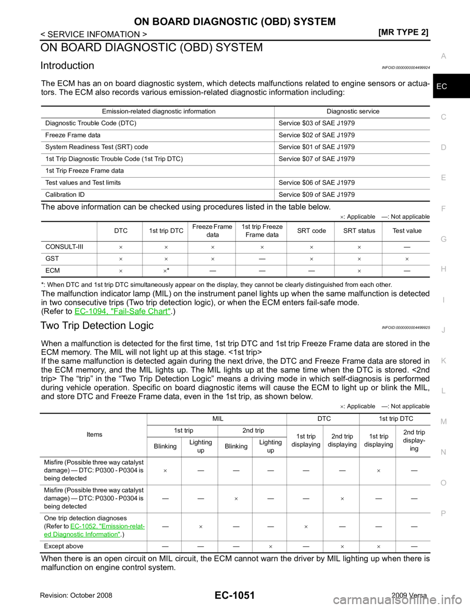
Introduction INFOID:0000000004499924
The ECM has an on board diagnostic system, which detects malfunctions related to engine sensors or actua-
tors. The ECM also records various emis sion-related diagnostic information including:
The above information can be checked using procedures listed in the table below. ×: Applicable —: Not applicable
*: When DTC and 1st trip DTC simultaneously appear on the display, they cannot be clearly distinguished from each other.
The malfunction indicator lamp (MIL) on the instrument panel lights up when the same malfunction is detected
in two consecutive trips (Two trip detection logic), or when the ECM enters fail-safe mode.
(Refer to EC-1094, " Fail-Safe Chart " .)
Two Trip Detection Logic INFOID:0000000004499925
When a malfunction is detected for the first time, 1st tr ip DTC and 1st trip Freeze Frame data are stored in the
ECM memory. The MIL will not light up at this stage. <1st trip>
If the same malfunction is detected again during the next drive, the DTC and Freeze Frame data are stored in
the ECM memory, and the MIL lights up. The MIL lights up at the same time when the DTC is stored. <2nd
trip> The “trip” in the “Two Trip Detection Logic” m eans a driving mode in which self-diagnosis is performed
during vehicle operation. Specific on board diagnostic item s will cause the ECM to light up or blink the MIL,
and store DTC and Freeze Frame data, even in the 1st trip, as shown below.
×: Applicable —: Not applicable
When there is an open circuit on MIL circuit, the ECM c annot warn the driver by MIL lighting up when there is
malfunction on engine control system. Emission-related diagnostic information Diagnostic service
Diagnostic Tr ouble Code (DTC) Service $03 of SAE J1979
Freeze Frame data Service $02 of SAE J1979
System Readiness Test (SRT) code Service $01 of SAE J1979
1st Trip Diagnostic Trou ble Code (1st Trip DTC) Service $07 of SAE J1979
1st Trip Freeze Frame data
Test values and Test limi ts Service $06 of SAE J1979
Calibration ID Servic e $09 of SAE J1979
DTC 1st trip DTC Freeze Frame
data 1st trip Freeze
Frame data SRT code SRT status Test value
CONSULT-III × × × × × × —
GST × × × —× × ×
ECM × ×* — — — ×— Items
MIL DTC 1st trip DTC
1st trip 2nd trip 1st trip
displaying 2nd trip
displaying 1st trip
displaying 2nd trip
display-
ing
Blinking Lighting
up Blinking
Lighting
up
Misfire (Possible three way catalyst
damage) — DTC: P0300 - P0304 is
being detected ×
— — — — — ×—
Misfire (Possible three way catalyst
damage) — DTC: P0300 - P0304 is
being detected — —
×— — ×— —
One trip detection diagnoses
(Refer to EC-1052, " Emission-relat-
ed Diagnostic Information " .)
—
×— — ×— — —
Except above — — — ×— × × —
Page 2408 of 4331
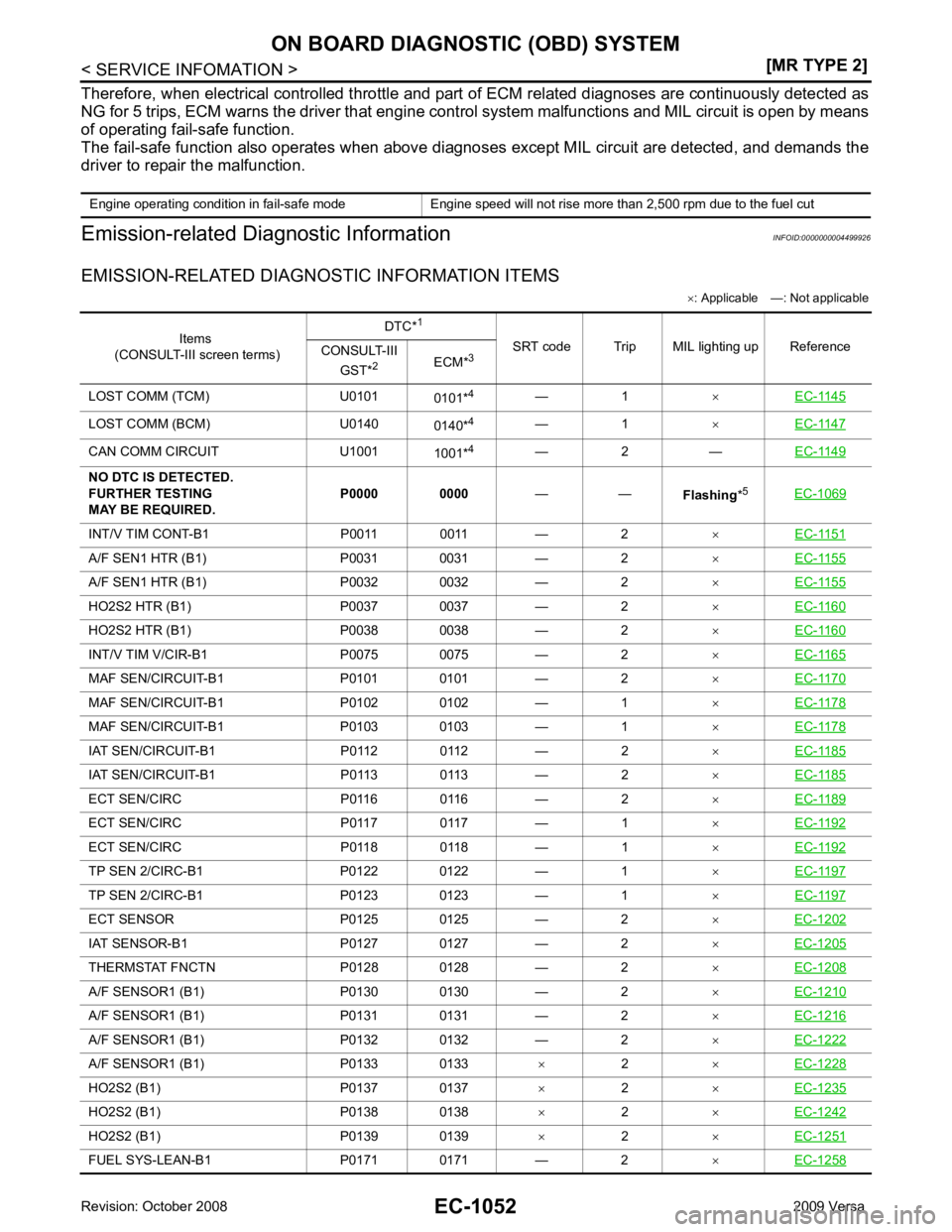
Items
(CONSULT-III screen terms) DTC*
1
SRT code Trip MIL lighting up Reference
CONSULT-III
GST* 2
ECM*3
LOST COMM (TCM) U0101 0101*4
— 1 ×EC-1145 LOST COMM (BCM) U0140
0140*4
— 1 ×EC-1147 CAN COMM CIRCUIT U1001
1001*4
— 2 — EC-1149INT/V TIM CONT-B1 P0011 0011 — 2
×EC-1151 A/F SEN1 HTR (B1) P0031 0031 — 2
×EC-1155 A/F SEN1 HTR (B1) P0032 0032 — 2
×EC-1155 HO2S2 HTR (B1) P0037 0037 — 2
×EC-1160 HO2S2 HTR (B1) P0038 0038 — 2
×EC-1160 INT/V TIM V/CIR-B1 P0075 0075 — 2
×EC-1165 MAF SEN/CIRCUIT-B1 P0101 0101 — 2
×EC-1170 MAF SEN/CIRCUIT-B1 P0102 0102 — 1
×EC-1178 MAF SEN/CIRCUIT-B1 P0103 0103 — 1
×EC-1178 IAT SEN/CIRCUIT-B1 P0112 0112 — 2
×EC-1185 IAT SEN/CIRCUIT-B1 P0113 0113 — 2
×EC-1185 ECT SEN/CIRC P0116 0116 — 2
×EC-1189 ECT SEN/CIRC P0117 0117 — 1
×EC-1192 ECT SEN/CIRC P0118 0118 — 1
×EC-1192 TP SEN 2/CIRC-B1 P0122 0122 — 1
×EC-1197 TP SEN 2/CIRC-B1 P0123 0123 — 1
×EC-1197 ECT SENSOR P0125 0125 — 2
×EC-1202 IAT SENSOR-B1 P0127 0127 — 2
×EC-1205 THERMSTAT FNCTN P0128 0128 — 2
×EC-1208 A/F SENSOR1 (B1) P0130 0130 — 2
×EC-1210 A/F SENSOR1 (B1) P0131 0131 — 2
×EC-1216 A/F SENSOR1 (B1) P0132 0132 — 2
×EC-1222 A/F SENSOR1 (B1) P0133 0133
×2 ×EC-1228 HO2S2 (B1) P0137 0137
×2 ×EC-1235 HO2S2 (B1) P0138 0138
×2 ×EC-1242 HO2S2 (B1) P0139 0139
×2 ×EC-1251 FUEL SYS-LEAN-B1 P0171 0171 — 2
×EC-1258
Page 2409 of 4331
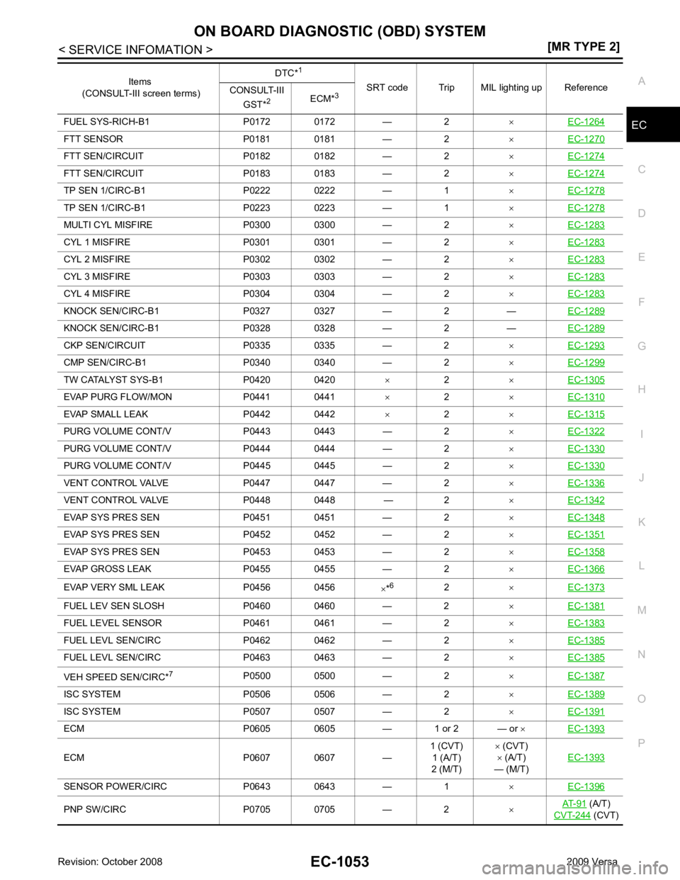
EC
NP
O
FUEL SYS-RICH-B1 P0172 0172 — 2
×EC-1264 FTT SENSOR P0181 0181 — 2
×EC-1270 FTT SEN/CIRCUIT P0182 0182 — 2
×EC-1274 FTT SEN/CIRCUIT P0183 0183 — 2
×EC-1274 TP SEN 1/CIRC-B1 P0222 0222 — 1
×EC-1278 TP SEN 1/CIRC-B1 P0223 0223 — 1
×EC-1278 MULTI CYL MISFIRE P0300 0300 — 2
×EC-1283 CYL 1 MISFIRE P0301 0301 — 2
×EC-1283 CYL 2 MISFIRE P0302 0302 — 2
×EC-1283 CYL 3 MISFIRE P0303 0303 — 2
×EC-1283 CYL 4 MISFIRE P0304 0304 — 2
×EC-1283 KNOCK SEN/CIRC-B1 P0327 0327 — 2 —
EC-1289KNOCK SEN/CIRC-B1 P0328 0328 — 2 —
EC-1289CKP SEN/CIRCUIT P0335 0335 — 2
×EC-1293 CMP SEN/CIRC-B1 P0340 0340 — 2
×EC-1299 TW CATALYST SYS-B1 P0420 0420
× 2 ×EC-1305 EVAP PURG FLOW/MON P0441 0441
×2 ×EC-1310 EVAP SMALL LEAK P0442 0442
×2 ×EC-1315 PURG VOLUME CONT/V P0443 0443 — 2
×EC-1322 PURG VOLUME CONT/V P0444 0444 — 2
×EC-1330 PURG VOLUME CONT/V P0445 0445 — 2
×EC-1330 VENT CONTROL VALVE P0447 0447 — 2
×EC-1336 VENT CONTROL VALVE P0448 0448 — 2
×EC-1342 EVAP SYS PRES SEN P0451 0451 — 2
×EC-1348 EVAP SYS PRES SEN P0452 0452 — 2
×EC-1351 EVAP SYS PRES SEN P0453 0453 — 2
×EC-1358 EVAP GROSS LEAK P0455 0455 — 2
×EC-1366 EVAP VERY SML LEAK P0456 0456
×*6
2 ×EC-1373 FUEL LEV SEN SLOSH P0460 0460 — 2
×EC-1381 FUEL LEVEL SEN
SOR P0461 0461 — 2 ×EC-1383 FUEL LEVL SEN/C
IRC P0462 0462 — 2 ×EC-1385 FUEL LEVL SEN/C
IRC P0463 0463 — 2 ×EC-1385 VEH SPEED SEN/CIRC*
7
P0500 0500 — 2 ×EC-1387 ISC SYSTEM P0506 0506 — 2
×EC-1389 ISC SYSTEM P0507 0507 — 2
×EC-1391 ECM P0605 0605 — 1 or 2 — or
×EC-1393 ECM P0607 0607 —
1 (CVT)
1 (A/T)
2 (M/T) ×
(CVT)
× (A/T)
— (M/T) EC-1393SENSOR POWER/CIRC P0643 0643 — 1
×EC-1396 PNP SW/CIRC P0705 0705 — 2
×AT-91 (A/T)
CVT-244 (CVT)
Items
(CONSULT-III screen terms) DTC*
1
SRT code Trip MIL lighting up Reference
CONSULT-III
GST* 2
ECM*3
Page 2410 of 4331
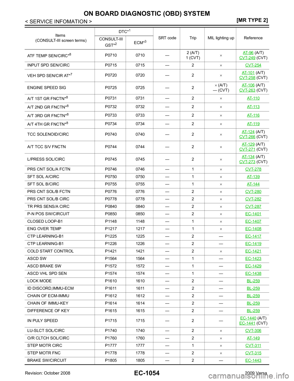
(A/T)
CVT-249 (CVT)
INPUT SPD SEN/CIRC P0715 0715 — 2 ×CVT-254 VEH SPD SEN/CIR AT*
7
P0720 0720 — 2 ×AT-101 (A/T)
CVT-258 (CVT)
ENGINE SPEED SIG P0725 0725 — 2 ×
(A/T)
— (CVT) AT-106 (A/T)
CVT-263 (CVT)
A/T 1ST GR FNCTN* 8
P0731 0731 — 2 ×AT-110 A/T 2ND GR FNCTN*
8
P0732 0732 — 2 ×AT-113 A/T 3RD GR FNCTN*
8
P0733 0733 — 2 ×AT-116 A/T 4TH GR FNCTN*
8
P0734 0734 — 2 ×AT-119 TCC SOLENOID/CIRC P0740 0740 — 2
×AT-124 (A/T)
CVT-266 (CVT)
A/T TCC S/V FNCTN P0744 0744 — 2 ×AT-129 (A/T)
CVT-271 (CVT)
L/PRESS SOL/CIRC P0745 0745 — 2 ×AT-134 (A/T)
CVT-273 (CVT)
PRS CNT SOL/A FCTN P0746 0746 — 1 ×CVT-278 SFT SOL A/CIRC P0750 0750 — 1
×AT-139 SFT SOL B/CIRC P0755 0755 — 1
×AT-144 PRS CNT SOL/B FCTN P0776 0776 — 2
×CVT-280 PRS CNT SOL/B CIRC P0778 0778 — 2
×CVT-282 TR PRS SENS/A CIRC P0840 0840 — 2
×CVT-287 P-N POS SW/CIRCUIT P0850 0850 — 2
×EC-1401 CLOSED LOOP-B1 P1148 1148 — 1
×EC-1407 ENG OVER TEMP P1217 1217 — 1
×EC-1408 CTP LEARNING-B1 P1225 1225 — 2 —
EC-1417CTP LEARNING-B1 P1226 1226 — 2 —
EC-1419COLD START CONTROL P1421 1421 — 2
×EC-1421 ASCD SW P1564 1564 — 1 —
EC-1423ASCD BRAKE SW P1572 1572 — 1 —
EC-1429ASCD VHL SPD SEN P1574 1574 — 1 —
EC-1438LOCK MODE P1610 1610 — 2 —
BL-259ID DISCORD,IMMU-ECM P1611 1611 — 2 —
BL-259CHAIN OF ECM-IMMU P1612 1612 — 2 —
BL-259CHAIN OF IMMU-KEY P1614 1614 — 2 —
BL-259DIFFERENCE OF KEY P1615 1615 — 2 —
BL-259IN PULY SPEED P1715 1715 — 2 —
EC-1440 (A/T)
EC-1441 (CVT)
LU-SLCT SOL/CIRC P1740 1740 — 2 ×CVT-306 O/R CLTCH SOL/CIRC P1760 1760 — 2
×AT-149 STEP MOTR CIRC P1777 1777 — 1
×CVT-311 STEP MOTR FNC P1778 1778 — 2
×CVT-315 BRAKE SW/CIRCUIT P1805 1805 — 2 —
EC-1443Items
(CONSULT-III screen terms) DTC*
1
SRT code Trip MIL lighting up Reference
CONSULT-III
GST* 2
ECM*3
Page 2411 of 4331
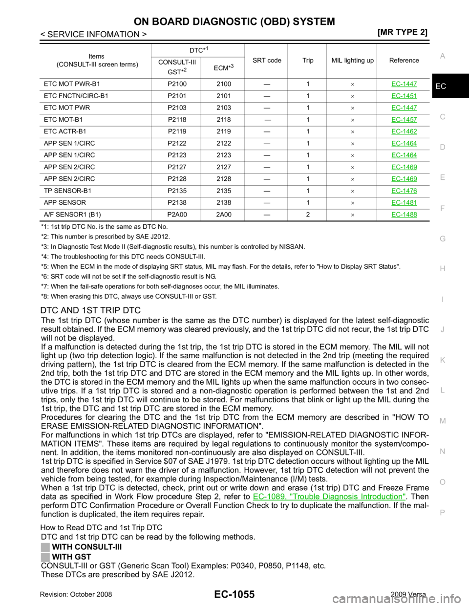
EC
NP
O
*1: 1st trip DTC No. is
the same as DTC No.
*2: This number is prescribed by SAE J2012.
*3: In Diagnostic Test Mode II (Self-diagnostic results), this number is controlled by NISSAN.
*4: The troubleshooting for this DTC needs CONSULT-III.
*5: When the ECM in the mode of displaying SRT status, MIL may flash. For the details, refer to "How to Display SRT Status".
*6: SRT code will not be set if the self-diagnostic result is NG.
*7: When the fail-safe operations for both self-diagnoses occur, the MIL illuminates.
*8: When erasing this DTC, al ways use CONSULT-III or GST.
DTC AND 1ST TRIP DTC The 1st trip DTC (whose number is the same as the DT C number) is displayed for the latest self-diagnostic
result obtained. If the ECM memory was cleared previously , and the 1st trip DTC did not recur, the 1st trip DTC
will not be displayed.
If a malfunction is detected during the 1st trip, the 1st trip DTC is stored in the ECM memory. The MIL will not
light up (two trip detection logic). If the same malfunc tion is not detected in the 2nd trip (meeting the required
driving pattern), the 1st trip DTC is cleared from the ECM memory. If the same malfunction is detected in the
2nd trip, both the 1st trip DTC and DTC are stored in t he ECM memory and the MIL lights up. In other words,
the DTC is stored in the ECM memory and the MIL light s up when the same malfunction occurs in two consec-
utive trips. If a 1st trip DTC is stored and a non-diagnostic operation is performed between the 1st and 2nd
trips, only the 1st trip DTC will continue to be stored. Fo r malfunctions that blink or light up the MIL during the
1st trip, the DTC and 1st trip DTC are stored in the ECM memory.
Procedures for clearing the DTC and the 1st trip DT C from the ECM memory are described in "HOW TO
ERASE EMISSION-RELATED DIAGNOSTIC INFORMATION".
For malfunctions in which 1st trip DTCs are displa yed, refer to "EMISSION-RELATED DIAGNOSTIC INFOR-
MATION ITEMS". These items are required by legal r egulations to continuously monitor the system/compo-
nent. In addition, the items monitored non-cont inuously are also displayed on CONSULT-III.
1st trip DTC is specified in Service $07 of SAE J1979. 1st trip DTC detection occurs without lighting up the MIL
and therefore does not warn the driver of a malfunction. However, 1st trip DTC detection will not prevent the
vehicle from being tested, for example during Inspection/Maintenance (I/M) tests.
When a 1st trip DTC is detected, check, print out or write down and erase (1st trip) DTC and Freeze Frame
data as specified in Work Flow procedure Step 2, refer to EC-1089, " Trouble Diagnosis Introduction " . Then
perform DTC Confirmation Procedure or Overall Function C heck to try to duplicate the malfunction. If the mal-
function is duplicated, the item requires repair.
How to Read DTC and 1st Trip DTC DTC and 1st trip DTC can be read by the following methods.
WITH CONSULT-III
WITH GST
CONSULT-III or GST (Generic Scan Tool ) Examples: P0340, P0850, P1148, etc.
These DTCs are prescribed by SAE J2012. ETC MOT PWR-B1 P2100 2100 — 1
×EC-1447 ETC FNCTN/CIRC-B1 P2101 2101 — 1
×EC-1451 ETC MOT PWR P2103 2103 — 1
×EC-1447 ETC MOT-B1 P2118 2118 — 1
×EC-1457 ETC ACTR-B1 P2119 2119 — 1
×EC-1462 APP SEN 1/CIRC P2122 2122 — 1
×EC-1464 APP SEN 1/CIRC P2123 2123 — 1
×EC-1464 APP SEN 2/CIRC P2127 2127 — 1
×EC-1469 APP SEN 2/CIRC P2128 2128 — 1
×EC-1469 TP SENSOR-B1 P2135 2135 — 1
×EC-1476 APP SENSOR P2138 2138 — 1
×EC-1481 A/F SENSOR1 (B1) P2A00 2A00 — 2
×EC-1488 Items
(CONSULT-III screen terms) DTC*
1
SRT code Trip MIL lighting up Reference
CONSULT-III
GST* 2
ECM*3