Page 5 of 313
Safety — Seats, seat belts and supplemental
restraint systemInstruments and controlsPre-driving checks and adjustmentsDisplay screen, heater, air conditioner and audio
systemsStarting and drivingIn case of emergencyAppearance and careMaintenance and do-it-yourselfTechnical and consumer informationIndex
Page 15 of 313
4. Driver supplemental air bag (P.1-28)/Horn
(P.2-27)
5. Meters/gauges (P.2-3)
6. Cruise control main/set switch* (P.5-16)
7. Trip computer mode/setting switch (P.2-8")
Hands-
Free Phone System* (P.4-31)4. Driver supplemental air bag (P.1-28)/Horn
(P.2-27)
5. Meters/gauges (P.2-3)
6. Cruise control main/set switch* (P.5-16)
7. Trip computer mode/setting switch (P.2-8)
8. Wiper/washer switch (P.2-21)9. Center ventilator (P.4-8)
10. Passenger supplemental air bag (P.1-28)
11. Side ventilators (P.4-8)
12. Soft top operating switch (for Roadster
models) (P.3-13)
13. VDC (Vehicle dynamic control) OFF switch*
(P.2-29) or TCS (Traction control system)
OFF switch* (P.2-29)
14. Fuel-filler door opener switch (P.3-23)
15. Hood lock release handle (P.3-8)
16. Fuse box (P.8-23)
17. Tilting steering wheel lock lever (P.3-25)
18. Ignition switch (P.5-6)
19. Navigation system display (P.4-2)*1 or In-
strument pocket (P.2-32)
20. Audio system (P.4-12)/Clock (P.2-30)
21. Rear window and outside mirror defroster
switch (P.2-23)
22. Hazard warning flasher switch (P.2-27)
23. Cup holder (P.2-33)
24. Heated seat switch* (P.2-28)
25. Heater/air conditioner control (P.4-9)
26. Power outlet (P.2-31)
*: if so equipped
*1: Refer to the separate Navigation System
Owner’s Manual.
SIC3266
INSTRUMENT PANEL0-10
Illustrated table of contents
Page 65 of 313
Hands-
Free Phone System (if so equipped)
4. Driver supplemental air bag/Horn
5. Meters/gauges6. Cruise control main/set switch
(if so equipped)
7. Trip computer mode/setting switch
8. Wiper/washer switch
9. Center ventilator
10. Passenger supplemental air bag11. Side ventilator
12. Soft top operating switch (for Roadster
models)
13. VDC (Vehicle dynamic control) OFF switch
(if so equipped) or TCS (Traction control
system) OFF switch (if so equipped)
14. Fuel-filler door opener switch
15. Hood lock release handle
16. Fuse box
17. Tilting steering wheel lock lever
18. Ignition switch/steering lock
19. Navigation system display* or Instrument
pocket
20. Audio system/Clock
21. Rear window and outside mirror defroster
switch
22. Hazard warning flasher switch
23. Cup holder
24. Heated seat switch (if so equipped)
25. Heater/air conditioner control
26. Power outlet
*: Refer to the separate Navigation System
Owner’s Manual.
SIC3266
INSTRUMENT PANEL2-2
Instruments and controls
Page 73 of 313

After 100 hours, the time will start from the reset
display again.Even if the display is switched to the other mode
while the time is starting, the stopwatch contin-
ues to advance until you stop the time in the
stopwatch mode. When the ignition switch is
turned to the OFF position, the time is reset.
Up-shift indicator setting (rpm) (for
manual transmission models)The up-shift indicator setting mode is used to
set the desired engine speed (rpm) for the
up-shift indicator (situated in the tachometer) to
illuminate. When the engine speed approaches
or reaches the set figure, the up-shift indicator
will flash or illuminate to show the driver the
timing for shifting into a higher gear. See “Driving
the vehicle” in the “5. Starting and driving”
section for the use of the up-shift indicator.
When the up-shift indicator setting mode is
selected, the rpm indicator blinks and the engine
speed currently set is displayed. (The initial
factory setting is 7,500 rpm.) The figure can be
changed between 2,000 and 9,000 rpm by
pushing trip computer setting switch
�B. Press-
ing the switch for less than approximately 1
second will add the figure by 100 rpm. If pushing
for more than approximately 1 second, the figure
will increase by 500 rpm.
If the battery cable is disconnected, the set
engine speed will be returned to the initial figure
(7,500 rpm).
Display priorityIf a low outside air temperature warning,
low dte (distance to empty) range warning
and low tire pressure warning occur simul-
taneously, other display modes switch au-
tomatically to the outside air temperature
display.
When trip computer mode switch
�A
is
pressed, the display switches to the mode
chosen before the warning display, but the
ICY indicator will continue blinking.
2-10
Instruments and controls
Page 94 of 313
or
side will
advance the time and the
or
side
will turn back the time.
3. Push the DISP button
�A
(Type A), or RPT
�B
button (Type B) to finish the adjustment.
ResettingType A (audio with 1 CD player):
Push the DISP
�A
and TUNE
�D
buttons.
Type B (audio with 6 CD changer):
Push the RPT
�B
and TUNE
�D
buttons.
The time will be set to a time signal.
For example, if these buttons are pushed while
the time is between 8:00 and 8:29, the display
will be reset to 8:00. If pushed while it is
between 8:30 and 8:59, the display will be reset
to 9:00. At the same time the display will return
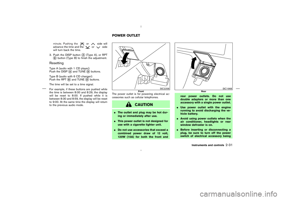
to the previous audio mode.The power outlet is for powering electrical ac-
cessories such as cellular telephones.
Page 141 of 313
” brightness control button
For Navigation System control buttons (other
than above), refer to the separate Navigation
System Owner’s Manual.
SAA1289
SAFETY NOTE
CONTROL PANEL BUTTONS —
WITH NAVIGATION SYSTEM4-2
Display screen, heater, air conditioner and audio systems
Page 142 of 313
SAA1290
Display screen, heater, air conditioner and audio systems
4-3
Page 143 of 313
SAA1291
4-4
Display screen, heater, air conditioner and audio systems


4. Driver supplemental air bag/Horn
5. Meters/gauges6. Cruise control main/set switch
(if so equipped)
7. Trip computer mode/setting switch
8. Wiper/washer sw")
, refer to the separate Navigation
System Owner’s Manual.
SAA1289
SAFETY NOTE
CONTROL PANEL BUTTONS —
WITH NAV")

