2009 MITSUBISHI ASX tow
[x] Cancel search: towPage 299 of 368

WARNING
l When the engine is not running, the
brake booster and power steering system
do not operate. This means higher brake
depression force and higher steering ef-
fort are required. Therefore, vehicle oper-
ation is more difficult than usual. CAUTION
l
Do
not leave the ignition switch in the
“LOCK” position or the operation mode
in OFF. The steering wheel will lock, caus-
ing loss of control.
3. Place
the gearshift lever in the “N” (Neutral) position (M/T) or the selector lever in the
“N” (NEUTRAL) position (CVT).
4. Turn on the hazard warning lamps if required by law.
(Follow the local driving laws and regula-
tions.) CAUTION
l
The
person in the vehicle being towed
must pay attention to the brake lamps of
the towing vehicle and make sure the
rope never becomes slack.
l Avoid sudden braking, sudden accelera-
tion and sharp turning; such operation
could cause damage to the towing hooks
or the tow rope.
People in the vicinity could be injured as
a result. CAUTION
l
When
towing or being towed down a long
slope, the brakes may overheat reducing
the effectiveness. In this situation, have
your vehicle transported by a tow truck.
l When the vehicle equipped with CVT is
to be towed by another vehicle with the
all wheels on the ground, make sure that
the towing speed and distance given be-
low are never exceeded, causing damage
to the transmission.
Towing speed: 40 km/h (25 mph)
Towing distance: 40 km (25 miles)
For the towing speed and the towing dis-
tance, follow the local driving laws and
regulations.
If your vehicle tows another vehicle 1. Take
out the towing hook, wheel nut wrench
and jack bar.
Refer to “Tools, jack and tyre repair kit” on
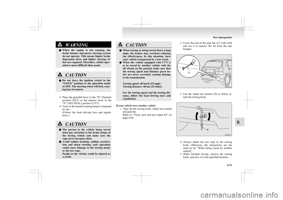
page 6-06. 2. Cover
the end of the jack bar (C) with cloth
and use it to remove the lid from the rear
bumper. 3. Use
the wheel nut wrench (D) to firmly at-
tach the towing hook. 4. Always
attach the tow rope to the towing
hook. Otherwise, the instructions are the
same as for “When being towed by another
vehicle”.
5. When finished towing, remove the towing hook, and stow it in the specified location. For emergencies
6-21 6
Page 300 of 368

Refer to “Tools,
jack and tyre repair kit” on
page 6-06.
When installing the bumper lid, align the
hook with the cut out area on the vehicle,
and firmly insert.
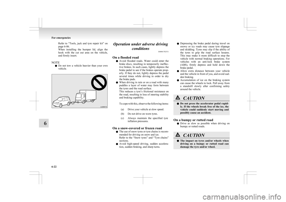
NOTE l Do not tow a vehicle heavier than your own
vehicle. Operation under adverse driving
conditions E00801702531
On a flooded road l Avoid
flooded roads. Water could enter the
brake discs, resulting in temporarily ineffec-
tive brakes. In such cases, lightly depress the
brake pedal to see if the brakes operate prop-
erly. If they do not, lightly depress the pedal
several times while driving in order to dry
the brake pads.
l When driving in rain or on a road with many
puddles a layer of water may form between
the tyres and the road surface.
This reduces a tyre’s frictional resistance on
the road, resulting in loss of steering stability
and braking capability.
To cope with this, observe the following items:
(a) Drive your vehicle at slow speed.
(b) Do not drive on worn tyres.
(c) Always maintain the specified tyre inflation pressures.
On a snow-covered or frozen road l The
use of snow tyres or tyre chains is recom-
mended for driving on snow and ice.
Refer to the “Snow tyres” and “Tyre chains”
sections.
l Avoid high-speed driving, sudden accelera-
tion, sudden braking, and sharp turns. l
Depressing
the brake pedal during travel on
snowy or icy roads may cause tyre slippage
and skidding. Tyres may slip if the ability of
the tyres to grip the road surface lessens.
This may make it more difficult to stop the
vehicle with normal braking operations. For
vehicles with an anti-lock brake system
(ABS), firmly depress and hold down the
brake pedal.
l Allow extra distance between your vehicle
and the vehicle in front of you, and avoid sud-
den braking.
l Accumulation of ice on the braking system
can cause the wheels to lock. Pull away from
a standstill slowly after confirming safety
around the vehicle. CAUTION
l
Do
not press the accelerator pedal rapid-
ly. If the wheels break free of the ice, the
vehicle could suddenly start moving and
possibly cause an accident.
On a bumpy or rutted road l Drive
as slow as possible when driving on
bumpy or rutted roads. CAUTION
l
The
impact on tyres and/or wheels when
driving on a bumpy or rutted road can
damage the tyre and/or wheel. For emergencies
6-22
6
Page 309 of 368

Bonnet
E01000302252
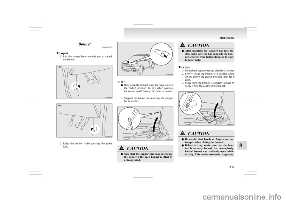
To open 1. Pull
the release lever towards you to unlock
the bonnet. 2. Raise
the bonnet while pressing the safety
lock. NOTE
l Only
open the bonnet when the wipers are in
the parked position. In any other position,
the wipers could damage the paint or bonnet.
3. Support the bonnet by inserting the support bar in its slot. CAUTION
l
Note
that the support bar may disengage
the bonnet if the open bonnet is lifted by
a strong wind. CAUTION
l
After
inserting the support bar into the
slot, make sure the bar supports the bon-
net securely from falling down on to your
head or body.
To close 1. Unlatch
the support bar and clip it in its holder.
2. Slowly lower the bonnet to a position about 20 cm above the closed position, then let it
drop.
3. Make sure the bonnet is securely locked by softly lifting the centre of the bonnet. CAUTION
l
Be
careful that hands or fingers are not
trapped when closing the bonnet.
l Before driving, make sure that the bon-
net is securely locked. An incompletely
locked bonnet can suddenly open while
driving. This can be extremely dangerous. Maintenance
8-03 8LHD RHD
Page 318 of 368
![MITSUBISHI ASX 2009 1.G Owners Manual Tyre inflation pressures
E01001402380Item Tyre size Front Rear At trailer towing
Front Rear
Normal tyre 215/65R16 98H
2.4 bar (35 psi) [240 kPa] 2.4 bar (35 psi) [240 kPa]
215/60R17 96H 2.2 bar (32 ps MITSUBISHI ASX 2009 1.G Owners Manual Tyre inflation pressures
E01001402380Item Tyre size Front Rear At trailer towing
Front Rear
Normal tyre 215/65R16 98H
2.4 bar (35 psi) [240 kPa] 2.4 bar (35 psi) [240 kPa]
215/60R17 96H 2.2 bar (32 ps](/manual-img/19/7566/w960_7566-317.png)
Tyre inflation pressures
E01001402380Item Tyre size Front Rear At trailer towing
Front Rear
Normal tyre 215/65R16 98H
2.4 bar (35 psi) [240 kPa] 2.4 bar (35 psi) [240 kPa]
215/60R17 96H 2.2 bar (32 psi) [220 kPa] 2.2 bar (32 psi) [220 kPa]
Temporary spare tyre T125/90D16
T155/90D16
4.2 bar (60 psi) [420 kPa]
—
215/65R16 2.4 bar (35 psi) [240 kPa] —Check the tyre inflation pressure of all the tyres while they are cold; if insufficient or excessive, adjust to the specified value.
After the tyre inflation pressure has been adjusted, check the tyres for damage and air leaks. Be sure to put caps on the valves.Maintenance
8-12
8
Page 331 of 368

Headlamps (low beam, except for vehi-
cles
with high intensity discharge head-
lamps) E01009300163
1. When replacing the bulb on the left side of
the vehicle in the case of diesel-powered ve-
hicles, remove the bolt (A) holding down the
relay box and move the relay box towards
the rear of the vehicle. *: Front of the vehicle 2. When replacing the bulb on the right side of
the vehicle in the case of diesel-powered ve-
hicles, remove the bolts (B) holding down
the reservoir tank and move the reservoir tank. *: Front of the vehicle
3. When
replacing the bulb on the right side of
the vehicle in the case of diesel-powered ve-
hicles, remove the clips (C) by prying with a
straight blade (or minus) screwdriver, and re-
move the side cover. *: Front of the vehicle4. Turn the cap (D) anticlockwise to remove it.
*: Front of the vehicle
5.
Turn the bulb (E) anticlockwise to remove it. *: Front of the vehicle Maintenance
8-25 8
Page 332 of 368

6. While holding down the tab (F), pull out the
socket (G). 7. To
install the bulb, perform the removal
steps in reverse. CAUTION
l
Handle
halogen lamp bulbs with care.
The gas inside halogen lamp bulbs is high-
ly pressurized, so dropping, knocking, or
scratching a halogen lamp bulb can cause
it to shatter.
l Never hold the halogen lamp bulb with a
bare hand, dirty glove, etc.
The oil from your hand could cause the
bulb to break the next time the head-
lamps are operated.
If the glass surface is dirty, it must be
cleaned with alcohol, paint thinner, etc.,
and refit it after drying it thoroughly. Headlamps (low beam, for vehicles
with high intensity discharge head-
lamps)
E01010100132
Do not attempt to disassemble or repair headlamps,
and do not attempt to replace their bulbs. WARNING
l A high voltage is present in the power cir-
cuit
and in the bulbs and bulb terminals.
To avoid the risk of an electric shock, con-
tact a MITSUBISHI MOTORS Author-
ized Service Point whenever repair or re-
placement is necessary. Headlamps (High-beam)
E01009400135
1. When
replacing the bulb on the left side of
the vehicle in the case of diesel-powered ve-
hicles, remove the bolt (A) holding down the
relay box and move the relay box towards
the rear of the vehicle. *: Front of the vehicle
2.
Turn the cap (B) anticlockwise to remove it. *: Front of the vehicleMaintenance
8-26
8
Page 333 of 368

3. Turn the bulb (C) anticlockwise to remove it.
*: Front of the vehicle
4. While holding down the tab (D), pull out the
socket (E). 5. To
install the bulb, perform the removal
steps in reverse. CAUTION
l
Handle
halogen lamp bulbs with care.
The gas inside halogen lamp bulbs is high-
ly pressurized, so dropping, knocking, or
scratching a halogen lamp bulb can cause
it to shatter.
l Never hold the halogen lamp bulb with a
bare hand, dirty glove, etc.
The oil from your hand could cause the
bulb to break the next time the head-
lamps are operated.
If the glass surface is dirty, it must be
cleaned with alcohol, paint thinner, etc.,
and refit it after drying it thoroughly. Position lamps
E01003700947
1. When
replacing the bulb on the left side of
the vehicle in the case of diesel-powered ve-
hicles, remove the bolt (A) holding down the
relay box and move the relay box towards
the rear of the vehicle. *: Front of the vehicle
2. When
replacing the bulb on the right side of
the vehicle in the case of diesel-powered ve-
hicles, remove the bolts (B) holding down
the reservoir tank and move the reservoir tank. *: Front of the vehicle Maintenance
8-27 8
Page 347 of 368

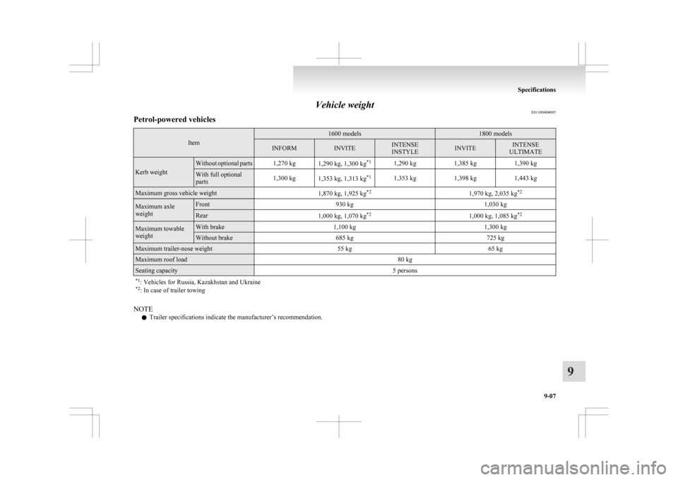
Vehicle weight
E01100404085
Petrol-powered vehicles Item 1600 models 1800 models
INFORM INVITE INTENSE
INSTYLE
INVITE INTENSE
ULTIMATE Kerb weight Without optional parts 1,270 kg
1,290 kg, 1,300 kg*1
1,290 kg 1,385 kg1,390 kg With full optional
parts
1,300 kg
1,353 kg, 1,313 kg *1
1,353 kg 1,398 kg1,443 kgMaximum gross vehicle weight
1,870 kg, 1,925 kg*2
1,970 kg, 2,035 kg*2Maximum axle
weight Front
930 kg 1,030 kgRear
1,000 kg, 1,070 kg*2
1,000 kg, 1,085 kg*2Maximum towable
weight With brake
1,100 kg 1,300 kgWithout brake
685 kg 725 kgMaximum trailer-nose weight
55 kg65 kgMaximum roof load
80 kgSeating capacity
5 persons
*1 : Vehicles for Russia, Kazakhstan and Ukraine
*2 : In case of trailer towing NOTE
l Trailer specifications indicate the manufacturer’s recommendation. Specifications
9-07 9