Page 129 of 172

REFERENCEAT A GLANCE CONTROLS DRIVING TIPS MOBILITY
127
Changing
1.Screw out the desired bulb counterclock-
wise, arrows1.
Additional bulbs are located behind the
sidewall of the cargo bay, arrow 2.
2.To insert the new bulb and replace the
cover, proceed in reverse order.
Rear fog lamp*
21 watt bulb, P 21 W
Access to the lamp via the back or underside of
the bumper.
The illustration shows the fog lamp in the
bumper of the MINI Cooper.
1.Screw out the bulb holder counterclockwise.
2.Screw out and replace the bulb.
3.To insert the new bulb and bulb holder, pro-
ceed in reverse order.
License plate lamps
5 watt bulb, C 5 W
1.Using a screwdriver, push the lamp to the
left in the tab of the lamp housing, arrow1.
2.Remove the lamp, arrow 2.
3.Replace the bulb.
4.Insert the lamp.
Center brake lamp
This lamp uses LED technology for operation. In
the event of a malfunction, contact your MINI
Dealer or a workshop that has specially trained
personnel working in accordance with the spec-
ifications of your MINI manufacturer.
Repairing a flat tire
Safety measures in the event of a break-
down:
Park the vehicle as far as possible from moving
traffic and switch on the hazard warning flash-
ers.
Turn the steering wheel until the front wheels
are in the straight-ahead position and engage
the steering wheel lock. Engage the parking
brake and shift into 1st or reverse gear or place
the selector lever in position P.
All passengers should be outside the vehicle and
in a safe place, e.g. behind a guardrail.
Erect a warning triangle or warning flasher at the
appropriate distance if necessary. Comply with
all safety guidelines and regulations.<
In the event of a flat tire, different procedures
should be followed depending on the equip-
ment included in your vehicle:
Page 130 of 172

Replacing components
128
>MINI Mobility System, refer to the following
section
>Run-Flat Tires, page111
>Tire change with space-saver spare tire,
page129
MINI Mobility System with onboard tool
kit and tire change set*
The MINI Mobility System with onboard tool kit
and tire change set
* is located under the floor
mat in the cargo bay.
1Filling canister
2Hexagon wrench
*
3Vehicle jack*
4Wheel stud wrench
5Flat screwdriver/Phillips screwdriver, towing
eyelet
6Compressor, hose with manometer and plug
for cigarette lighter socket
7Package with filling hose, valve remover and
valve core
Use of the MINI Mobility System may be
ineffective if the tire puncture measures
approx. 1/8 in/4 mm or more. Contact the near-
est MINI Dealer if the tire cannot be made driv-
able with the MINI Mobility System.<
Liquid sealant
1Filling hose
2Filling canister
Filling
1.Shake the filling canister.
2.Screw the filling hose onto the filling canis-
ter.
3.Unscrew the dust cap from the valve of the
defective tire.
4.Screw out the valve core with the valve
remover. The valve remover is located in a
package with the filling hose.
5.Remove the cap from the filling hose.
6.Push the filling hose onto the tire valve.
7.Hold the filling canister with the cap down
and squeeze.
8.Squeeze the entire contents of the canister
into the tire.
9.Remove the filling hose.
10.Screw the valve core into the tire valve with
the valve remover.
In the event of a lost or dirty valve core
you will find another valve core in the
package with the filling hose.
Remember that the liquid canister must be
replaced every four years if the equipment has
not been used.<
Page 131 of 172

REFERENCEAT A GLANCE CONTROLS DRIVING TIPS MOBILITY
129
Compressor
1Hose with manometer
2Compressor
3Connector for power supply
Reinflating the tire
1.Screw hose1 with manometer onto the tire
valve.
2.Insert connector 3 into the lighter socket in
the interior of the vehicle, page87.
3.Switch on compressor2.
4.Inflate the tire to at least 26 psi/180 kPa and
at most 36 psi/250 kPa.
To check the air pressure, shut off the device
for a short time.
Do not run the compressor for longer
than 6 minutes, otherwise the device
will overheat and possibly be damaged.<
If an air pressure of 26 psi/180 kPa is not reached:
1.Unscrew hose 1 and drive the vehicle for-
ward and backward about 33 ft/10 m to dis-
tribute the liquid sealant in the tires evenly.
2.Repeat the procedure.
If an air pressure of 26 psi/180 kPa still
cannot be reached, the tire is too severely
damaged. Please contact the nearest MINI
Dealer.<
Distributing liquid sealant
Immediately drive for approx. 10 minutes, so
that the liquid sealant is uniformly distributed.
Do not exceed speeds of
40 mph/60 km/h.
If possible, do not drop below
10 mph/20 km/h.<
Checking tire inflation pressure
1.After driving for approx. 10 minutes, pull
over at a suitable location.
2.Screw the hose with manometer back onto
the tire valve.
3.Check the tire inflation pressure.
The tire pressure must be at least
18 psi/130 kPa. If it is not, do not con-
tinue driving.<
If a tire pressure of at least 18 psi/130 kPa is dis-
played:
1.Switch on the compressor. Correct the tire
inflation pressure to the specified value,
page102.
2.Replace the tire as soon as possible.
Driving on
Do not exceed the permitted maximum
speed of 50 mph/80 km/h; doing so may
result in an accident.<
Replace the defective tire as soon as possible
and have the new wheel/tire assembly bal-
anced.
Have the MINI Mobility System refilled.
Tire change set
When changing a tire, always observe the safety
measures and the procedure for changing tires
described below.
In case of a flat tire the tire change set is
not needed due to the availability of the
MINI Mobility System.<
Changing wheels
Space-saver spare tire*
To change a space-saver spare tire, proceed as
follows:
>Remove space-saver spare tire, page130
>Prepare for tire change, page131
>Jack up vehicle, page131
>Mount space-saver spare tire, page132
Page 132 of 172

Replacing components
130
>Tighten lug bolts, page132
>Drive with space-saver spare tire, page131
Tire change set for a space-saver spare
tire*
On vehicles with a space-saver spare tire, the
tire change set with onboard tools is stored
under the floor mat in the cargo bay.
1Chock, folding
2Hub cover remover
3Wheel stud wrench
4Vehicle jack
5Special wrench for removing the space-
saver spare tire
6Flat screwdriver/Phillips screwdriver
7Towing eyelet
8Lifting handle
The onboard tool kit includes a pouch with a
plastic bag in which you can place the damaged
wheel.
Removing the space-saver spare tire
The screw connection of the space-saver spare
tire is under the floor mat in the cargo bay, on
the base of the storage compartment for the tire
change set.1.Unscrew the screw connection with the spe-
cial wrench.
2.Take out the cover panel.
3.Screw the lifting handle from the onboard
tool kit onto the thread.
4.Raise the lifting handle slightly.
5.Squeeze the securing spring.
6.The space-saver spare tire is released and
must be held by the lifting handle.
7.Lower the space-saver spare tire with the
lifting handle.
8.Unscrew the lifting handle.
Page 133 of 172

REFERENCEAT A GLANCE CONTROLS DRIVING TIPS MOBILITY
131
9.Pull the space-saver spare tire underneath
the vehicle out towards the rear.
10.Position the space-saver spare tire with the
valve facing upward.
11.Unscrew the valve extension from the valve
of the space-saver spare tire.
12.Unscrew the dust cap from the extension
and place it on the valve of the space-saver
spare tire.
Due to its different dimensions, the dam-
aged wheel cannot be placed in the recess
for the space-saver spare tire.<
Driving with the space-saver spare tire
Drive cautiously and do not exceed a
speed of 50 mph/80 km/h. Changes may
occur in vehicle handling such as lower track sta-
bility during braking, longer braking distances
and changes in self-steering properties when
close to the handling limit. These properties are
more noticeable with winter tires.<
Only one space-saver spare tire may be
mounted at one time. Mount a wheel and
tire of the original size as soon as possible, to
avoid any safety risks.<
Check the tire inflation pressure at the ear-
liest opportunity and correct it if neces-
sary. Replace the defective tire as soon as possi-
ble and have the new wheel/tire assembly
balanced.<
Preparing for a tire change
Observe the safety precautions regarding
flat tires on page127.<
Additional safety measures when chang-
ing tires:
Only change the tire when parked on a surface
that is level, firm and not slippery.
The vehicle or the jack could slip sideways on
soft or slippery support surfaces, such as snow,
ice, flagstones, etc.
Do not use a wooden block or similar object as a
support base for the jack, as this would prevent
it from extending to its full support height and
reduce its load-carrying capacity.
Do not lie under the vehicle or start the engine
when the vehicle is supported by the jack; other-
wise there is a risk of fatal injury.<
1.Place the foldable chock
* behind the front
wheel on the other side of the vehicle or in
front of the wheel if the vehicle is on an
incline. If the wheel is changed on a surface
with a more severe slope, take additional
precautions to secure the vehicle from roll-
ing.
2.Uncover the lug bolts if necessary.
If the wheel is equipped with a hub cover,
pry it off using the screwdriver from the tire
change kit.
3.Loosen the lug bolts by a half turn.
Jacking up the vehicle
The vehicle jack is designed for changing
wheels only. Do not attempt to raise
another vehicle model with it or to raise any load
of any kind. To do so could cause accidents and
personal injury.<
Page 134 of 172

Replacing components
132
1.Place the jack at the jacking point closest to
the wheel.
The jack base must be perpendicular to the
surface beneath the jacking point.
2.During jacking up, insert the jack head in the
square recess of the jacking point.
3.Jack the vehicle up until the wheel you are
changing is raised off the ground.
Mounting the space-saver spare tire
1.Unscrew the lug bolts and remove the
wheel.
2.Remove accumulations of mud or dirt from
the mounting surfaces of the wheel and
hub. Clean the lug bolts.
3.Lift the new wheel into place.
4.Screw at least two lug bolts finger-tight into
opposite bolt holes.
5.Screw in the remaining bolts.
6.Tighten all the lug bolts firmly in a diagonal
pattern.
7.Lower the vehicle.
8.Remove the jack.
Tightening the lug bolts
Tighten the lug bolts in a diagonal pattern.
Immediately have the wheels checked
with a calibrated torque wrench to ensure
that the lug bolts are firmly seated. Otherwise,
incorrectly tightened lug bolts can present a
safety hazard.<
Tightening torque: 103.3 lb ft or 140 Nm.
Replace the defective tire as soon as possible
and have the new wheel/tire assembly bal-
anced.
Vehicle battery
Have any work on the battery, including
battery replacement, carried out only by a
MINI Dealer or a workshop that has specially
trained personnel working in accordance with
the specifications of the MINI manufacturer.<
Battery care
The battery is 100 % maintenance-free, the
electrolyte will last for the life of the battery
when the vehicle is operated in a temperate cli-
mate.
Charging the battery
Only charge the battery in the vehicle when the
engine is off. Connections, refer to Jump starting
on page134.
Disposal
After replacing old batteries, return the
used batteries to your MINI Dealer or to a
recycling point. Maintain the battery in an
upright position for transport and storage.
Always secure the battery against tipping over
during transport.<
Power failure
After a temporary power loss, some equipment
may not be fully functional and may require ini-
tialization. Individual settings are also lost and
must be reprogrammed:
>Time and date
These values must be updated, page59.
>Radio
Stations must be stored again, refer to the
separate Owner's Manual for Radio.
>Glass sunroof, electric
It may only be possible to raise the sunroof,
if applicable. The system must be initialized.
Contact your nearest MINI Dealer.
Page 135 of 172
REFERENCEAT A GLANCE CONTROLS DRIVING TIPS MOBILITY
133
Fuses
Do not attempt to repair a blown fuse or
replace it with a fuse of a different color or
Ampere rating. To do this could cause a fire in
the vehicle resulting from a circuit overload.
Have the fuse changed only by a MINI Dealer or
a workshop that has specially trained personnel
working in accordance with the specifications of
the MINI manufacturer.<
A fuse allocation diagram is located on the inside
of the fuse box cover panels.
In the engine compartment
Opening the cover
Press the latch.
In the vehicle interior
On the right side of the footwell.
Opening the cover
Press out at the recess.
Page 136 of 172

Giving and receiving assistance
134
Giving and receiving assistance
Roadside Assistance
The Roadside Assistance service is there to assist
you around the clock in the event of a break-
down, including on weekends and public holi-
days.
The phone numbers of the Roadside Assistance
in your home country can be found in the Con-
tact brochure.
First aid pouch*
Some of the articles contained in the first aid
pouch have a limited service life. Therefore,
check the expiration dates of the contents regu-
larly and replace any items in good time, if nec-
essary.
By way of example, the illustration shows the
cargo bay in the MINI.
The first aid pouch is located on the cargo bay
floor by the left side trim panel.
Warning triangle*
MINI
On the inside of the tailgate.
Press the tab to take it out.
MINI Convertible
The warning triangle is located at the bottom of
the luggage compartment floor.
Jump starting
If the car's own battery is flat, your MINI's engine
can be started by connecting two jumper cables
to another vehicle's battery. You can also use
the same method to help start another vehicle.
Only use jumper cables with fully-insulated
clamp handles.
Do not touch any electrically live parts
when the engine is running, or a fatal acci-
dent may occur. Carefully adhere to the follow-
ing sequence, both to prevent damage to one or
both vehicles, and to guard against possible per-
sonal injuries.<
Preparation
1.Check whether the battery of the other vehi-
cle has a voltage of 12 volts and approxi-
mately the same capacitance in Ah. This
information can be found on the battery.
2.Switch off the engine of the support vehicle.
3.Switch off any consumers in both vehicles.
 1
1 2
2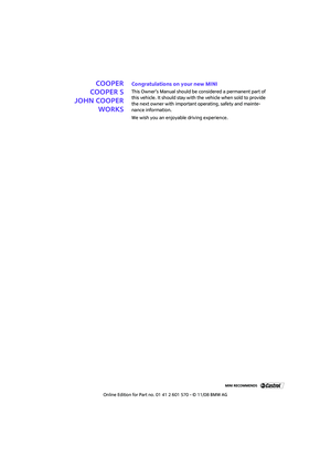 3
3 4
4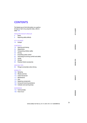 5
5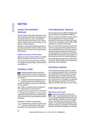 6
6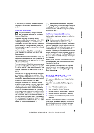 7
7 8
8 9
9 10
10 11
11 12
12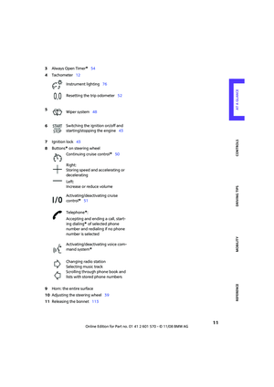 13
13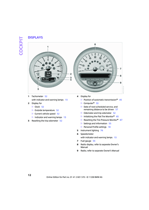 14
14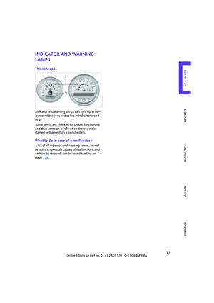 15
15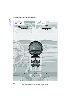 16
16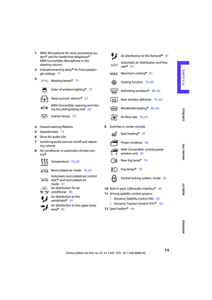 17
17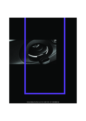 18
18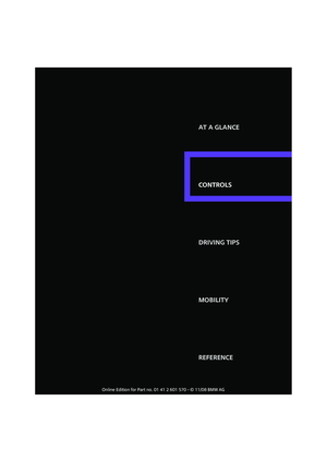 19
19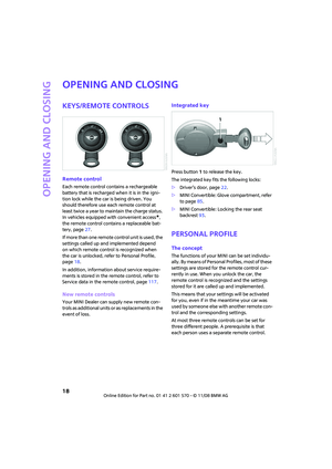 20
20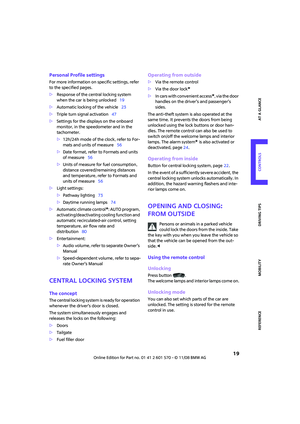 21
21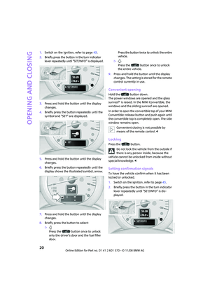 22
22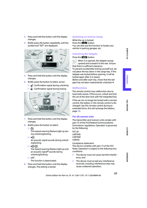 23
23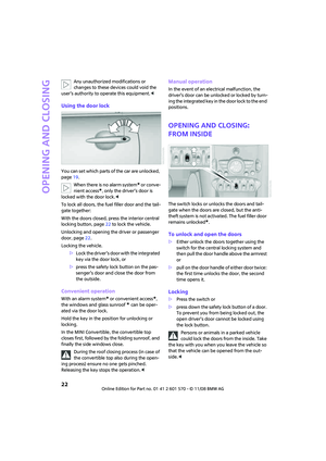 24
24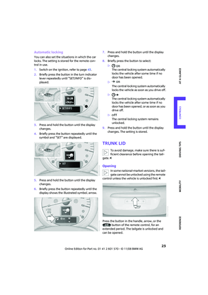 25
25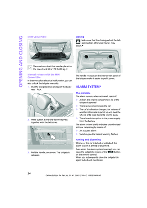 26
26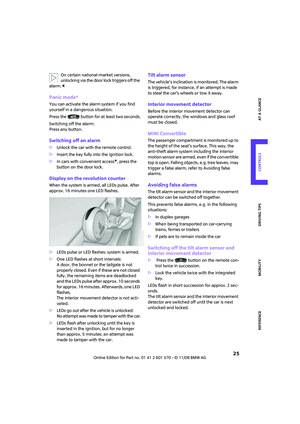 27
27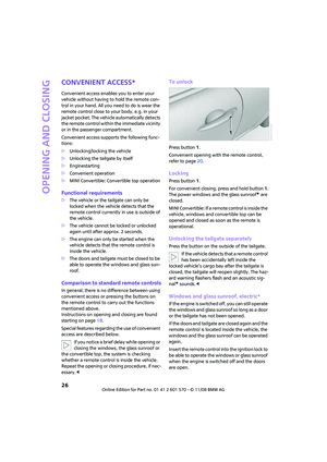 28
28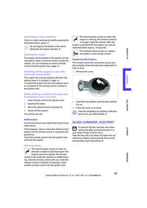 29
29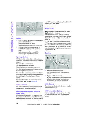 30
30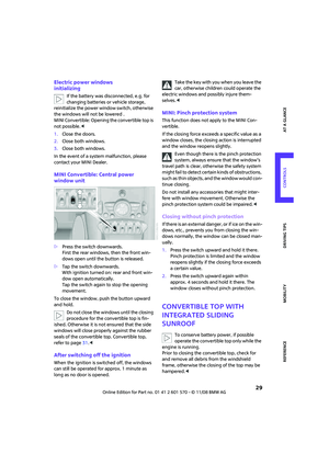 31
31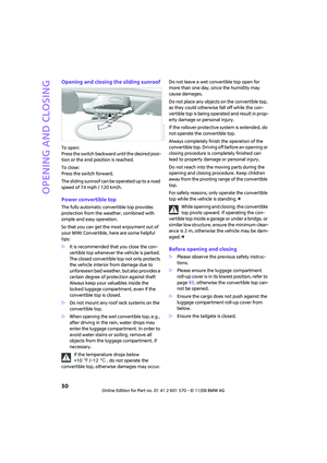 32
32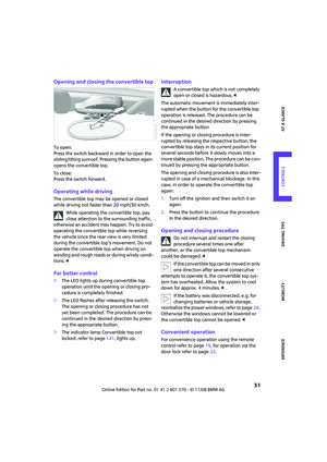 33
33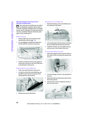 34
34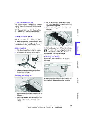 35
35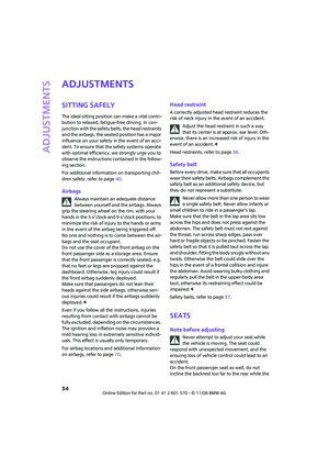 36
36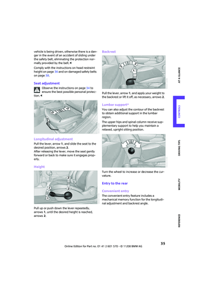 37
37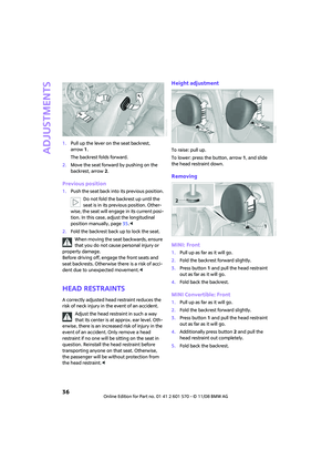 38
38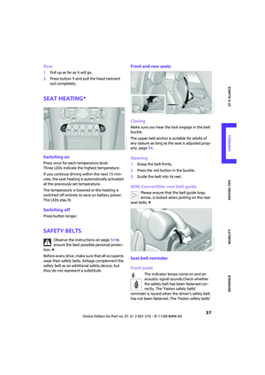 39
39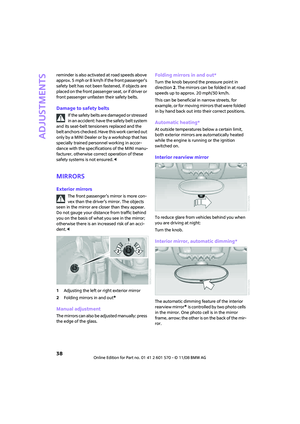 40
40 41
41 42
42 43
43 44
44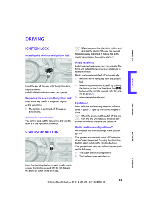 45
45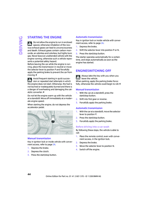 46
46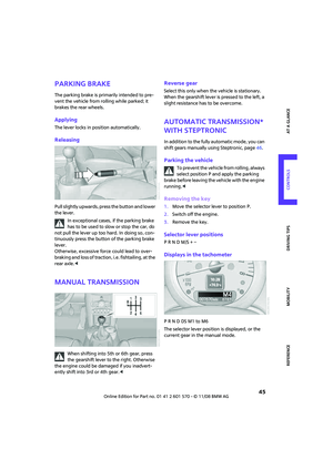 47
47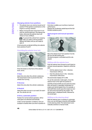 48
48 49
49 50
50 51
51 52
52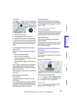 53
53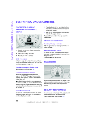 54
54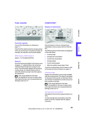 55
55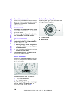 56
56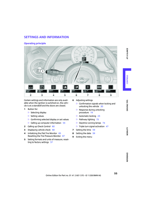 57
57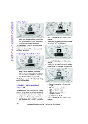 58
58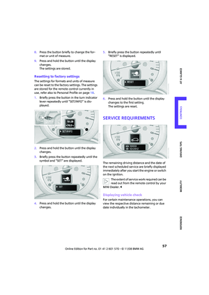 59
59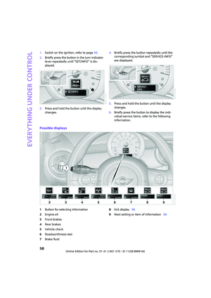 60
60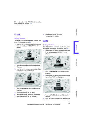 61
61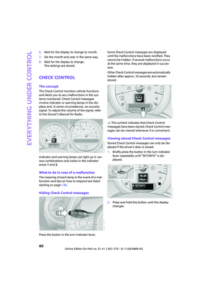 62
62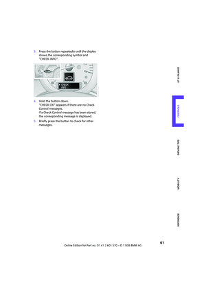 63
63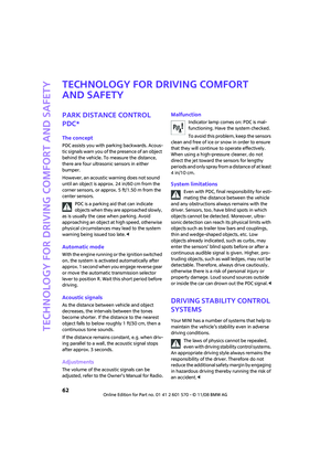 64
64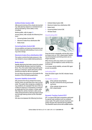 65
65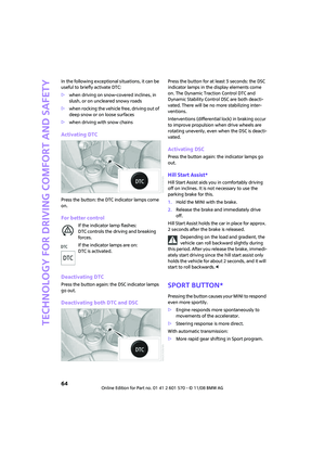 66
66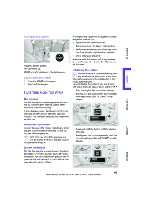 67
67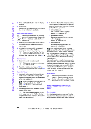 68
68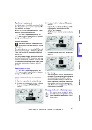 69
69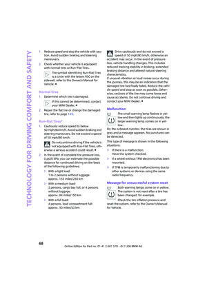 70
70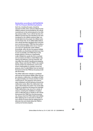 71
71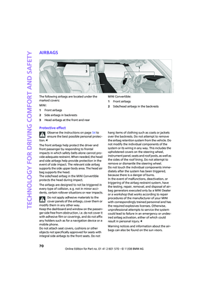 72
72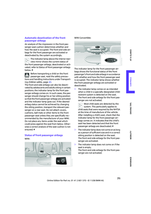 73
73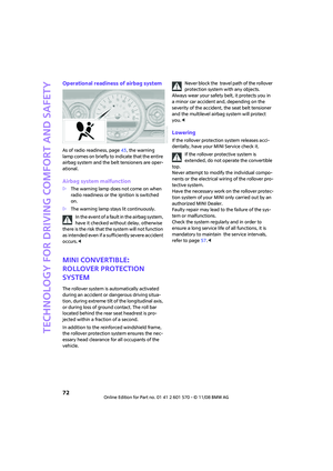 74
74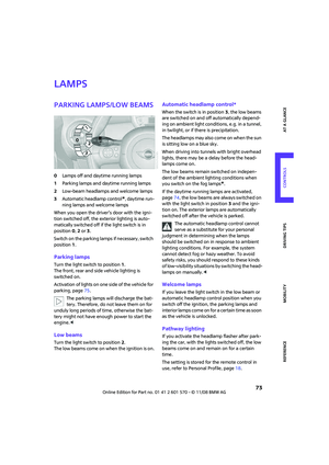 75
75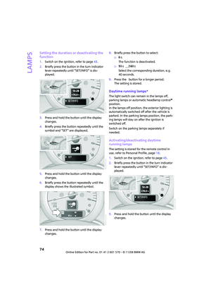 76
76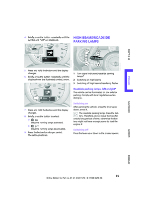 77
77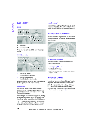 78
78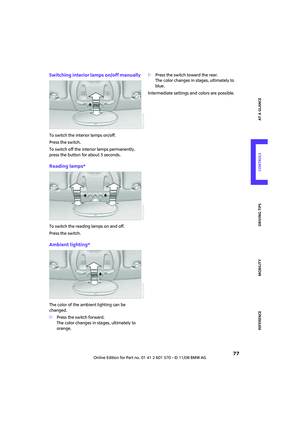 79
79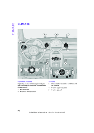 80
80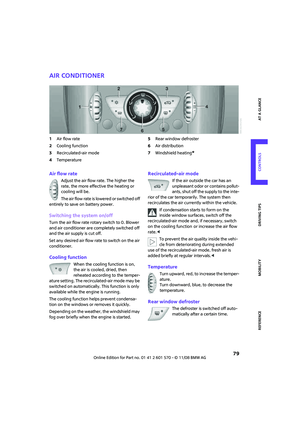 81
81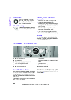 82
82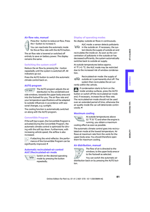 83
83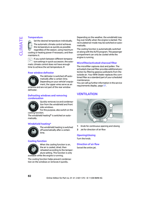 84
84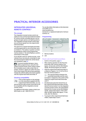 85
85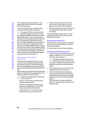 86
86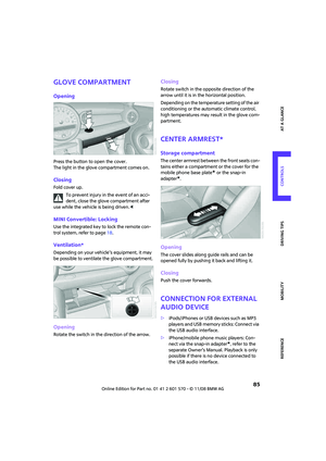 87
87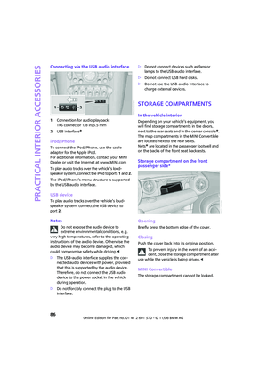 88
88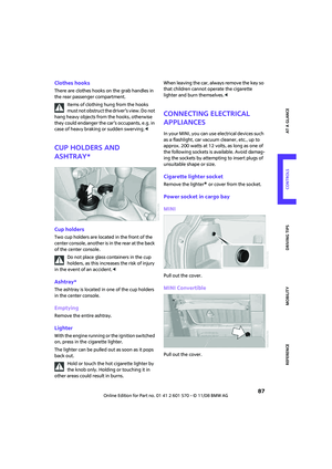 89
89 90
90 91
91 92
92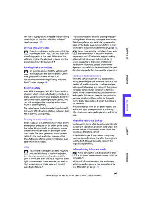 93
93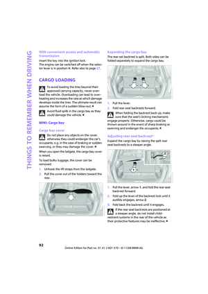 94
94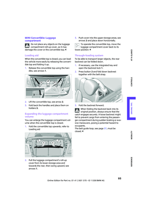 95
95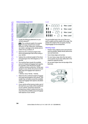 96
96 97
97 98
98 99
99 100
100 101
101 102
102 103
103 104
104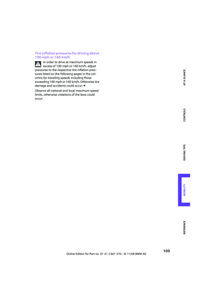 105
105 106
106 107
107 108
108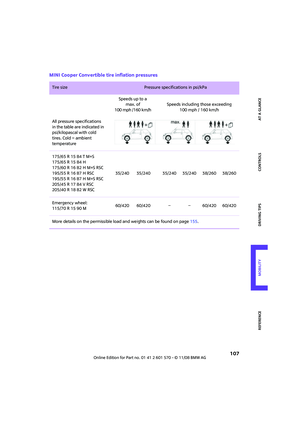 109
109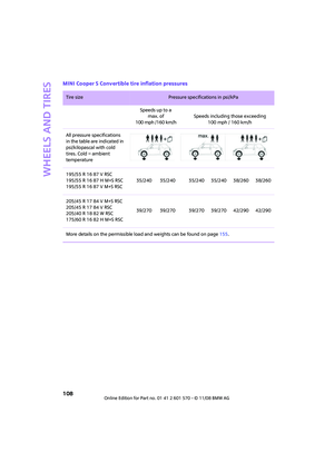 110
110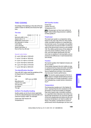 111
111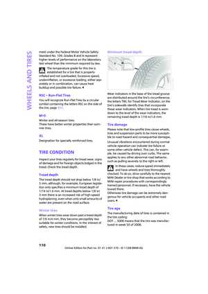 112
112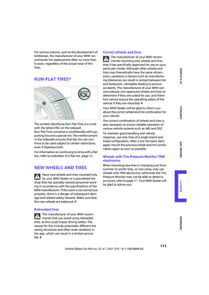 113
113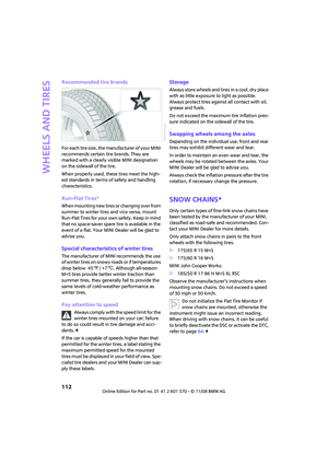 114
114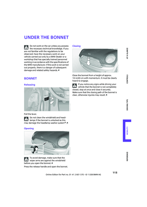 115
115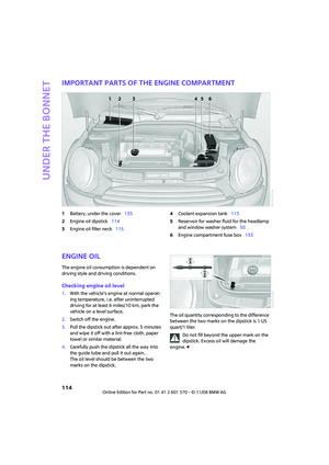 116
116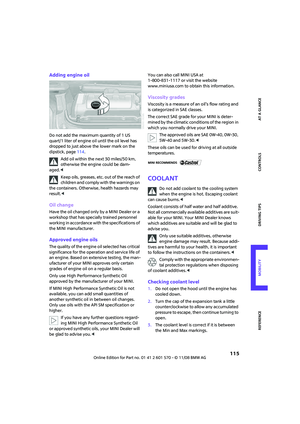 117
117 118
118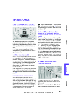 119
119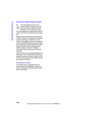 120
120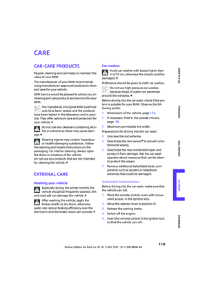 121
121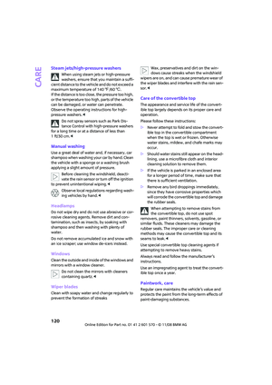 122
122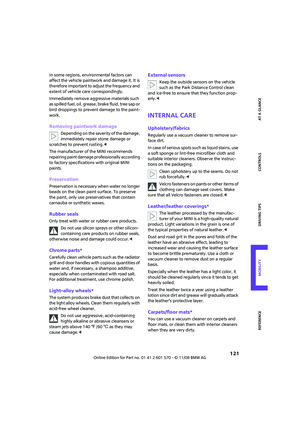 123
123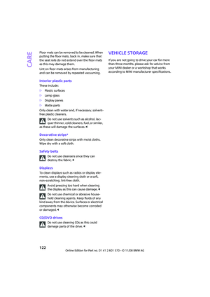 124
124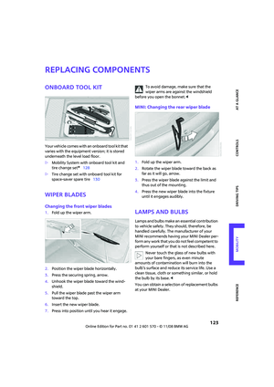 125
125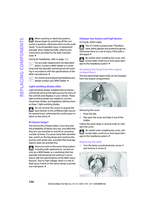 126
126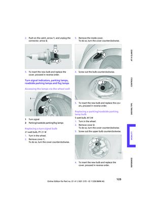 127
127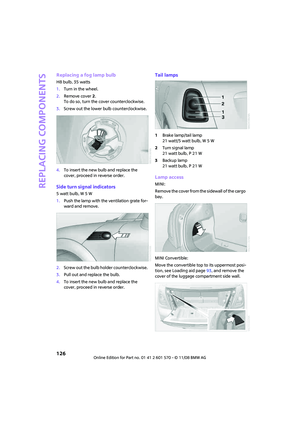 128
128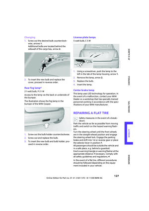 129
129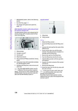 130
130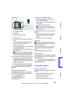 131
131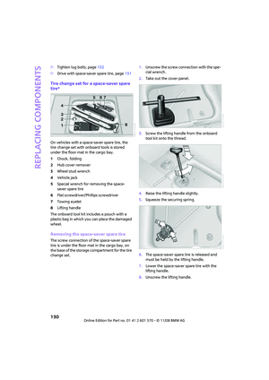 132
132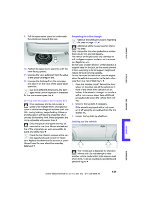 133
133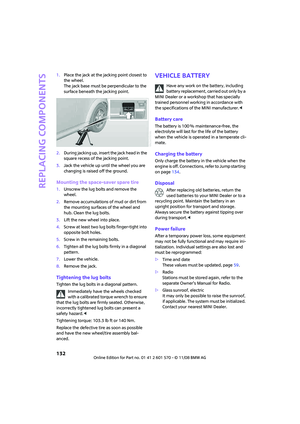 134
134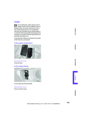 135
135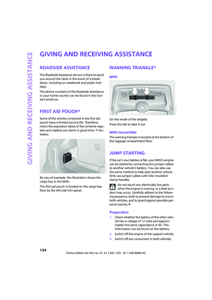 136
136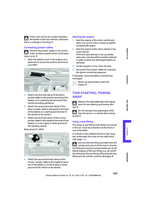 137
137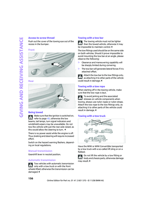 138
138 139
139 140
140 141
141 142
142 143
143 144
144 145
145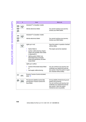 146
146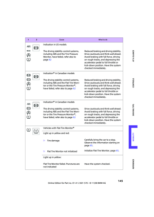 147
147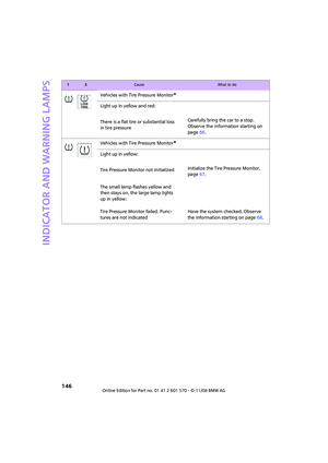 148
148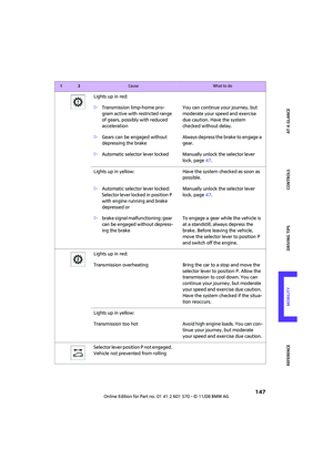 149
149 150
150 151
151 152
152 153
153 154
154 155
155 156
156 157
157 158
158 159
159 160
160 161
161 162
162 163
163 164
164 165
165 166
166 167
167 168
168 169
169 170
170 171
171