2009 MERCEDES-BENZ GL SUV lock
[x] Cancel search: lockPage 164 of 309
Roof rack system*
G
Risk of accident and injury
An incorrectly secured roof rack, ski rack or
load could become detached from the vehi-
cle. These objects may be thrown around and
can injure you or others, or cause an accident.
Follow the roof rack/ski rack manufacturer's
installation instructions and special instruc-
tions for use.
The roof load raises the vehicle's centre of
gravity, thereby affecting vehicle handling.
You must always observe the maximum roof
load of 100 kg. Always adapt your driving style
to the prevailing road, traffic and weather
conditions and drive with particular care if the
roof is laden.
! Mercedes-Benz recommends that you
only use roof rack systems which have
been tested and approved for Mercedes-
Benz vehicles. This helps to prevent dam-
age to the vehicle.
Position the load on the roof rack in such a
way that the vehicle will not sustain dam-
age even when it is in motion.
Depending on the vehicle's equipment,
make sure that you can:
R raise the sliding/tilting sunroof* fully
R open the tailgate fully X
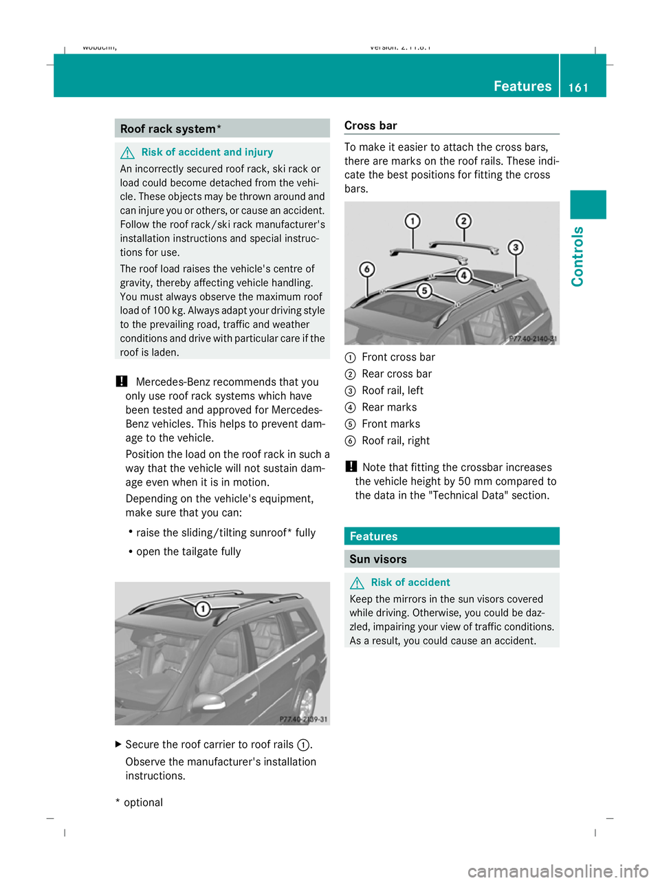
Secure the roof carrier to roof rails :.
Observe the manufacturer's installation
instructions. Cross bar To make it easier to attach the cross bars,
there are marks on the roof rails. These indi-
cate the best positions for fitting the cross
bars. :
Front cross bar
; Rear cross bar
= Roof rail, left
? Rear marks
A Front marks
B Roof rail, right
! Note that fitting the crossbar increases
the vehicle height by 50 mm compared to
the data in the "Technical Data" section. Features
Sun visors
G
Risk of accident
Keep the mirrors in the sun visors covered
while driving. Otherwise, you could be daz-
zled, impairing your view of traffic conditions.
As a result, you could cause an accident. Features
161Controls
* optional
X164_AKB; 2; 3, en-GB
wobuchh,
Version: 2.11.8.1 2009-03-31T14:14:58+02:00 - Seite 161 Z
Dateiname: 6515431202_buchblock.pdf; erzeugt am 01. Apr 2009 00:17:40; WK
Page 165 of 309
:
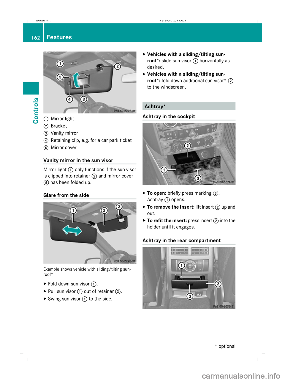
Mirror light
; Bracket
= Vanity mirror
? Retaining clip, e.g. for a car park ticket
A Mirror cover
Vanity mirror in the sun visor Mirror light
:only functions if the sun visor
is clipped into retainer ;and mirror cover
A has been folded up.
Glare from the side Example shows vehicle with sliding/tilting sun-
roof*
X Fold down sun visor :.
X Pull sun visor :out of retainer =.
X Swing sun visor :to the side. X
Vehicles with a sliding/tilting sun-
roof*: slide sun visor :horizontally as
desired.
X Vehicles with a sliding/tilting sun-
roof*: fold down additional sun visor* ;
to the windscreen. Ashtray*
Ashtray in the cockpit X
To open: briefly press marking =.
Ashtray :opens.
X To remove the insert: lift insert;up and
out.
X To refit the insert: press insert;into the
holder until it engages.
Ashtray in the rear compartment 162
FeaturesControls
* optional
X164_AKB; 2; 3, en-GB
wobuchh,
Version: 2.11.8.1 2009-03-31T14:14:58+02:00 - Seite 162
Dateiname: 6515431202_buchblock.pdf; erzeugt am 01. Apr 2009 00:17:41; WK
Page 166 of 309
X
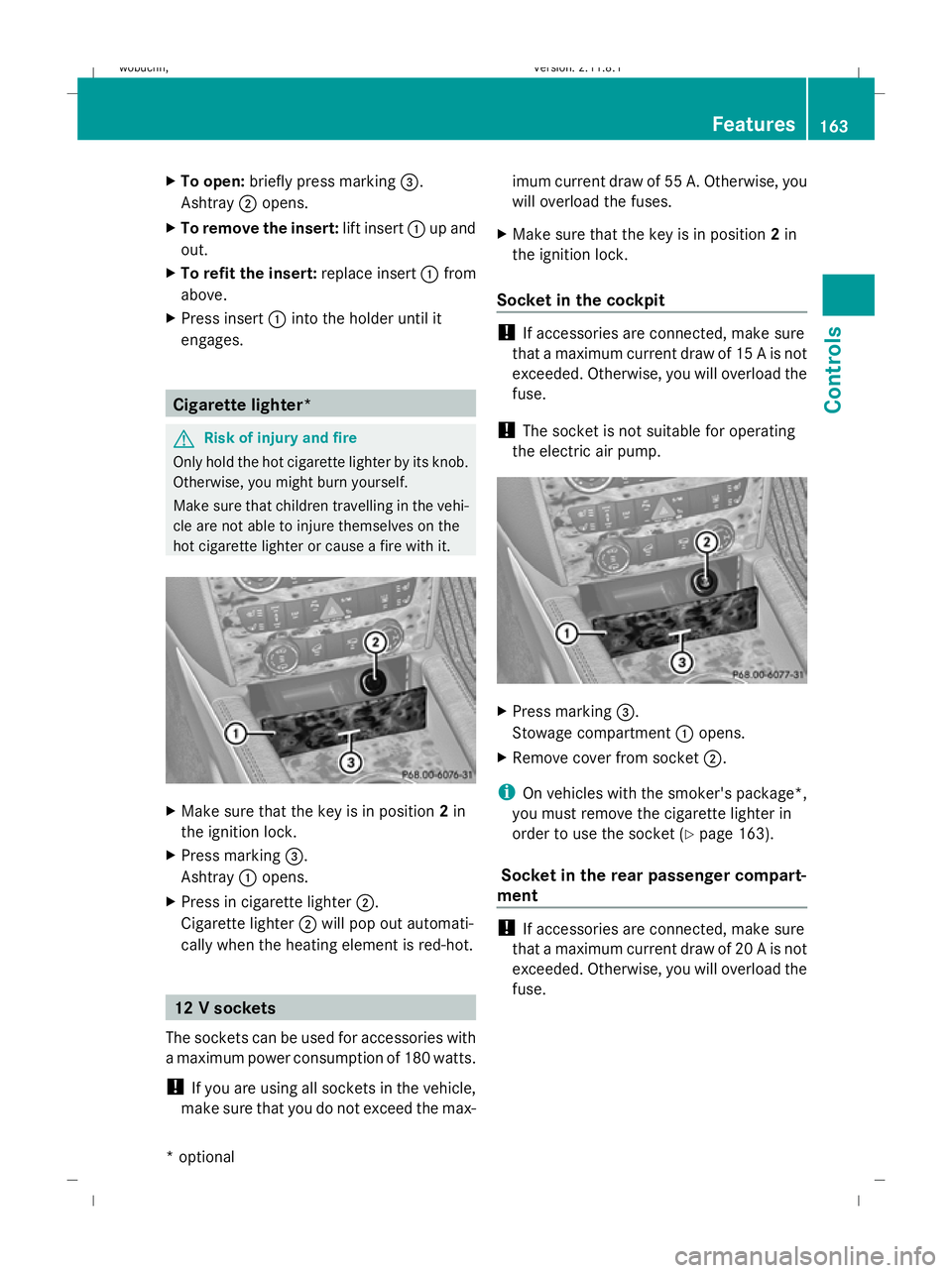
To open: briefly press marking =.
Ashtray ;opens.
X To remove the insert: lift insert:up and
out.
X To refit the insert: replace insert:from
above.
X Press insert :into the holder until it
engages. Cigarette lighter*
G
Risk of injury and fire
Only hold the hot cigarette lighter by its knob.
Otherwise, you might burn yourself.
Make sure that children travelling in the vehi-
cle are not able to injure themselves on the
hot cigarette lighter or cause a fire with it. X
Make sure that the key is in position 2in
the ignition lock.
X Press marking =.
Ashtray :opens.
X Press in cigarette lighter ;.
Cigarette lighter ;will pop out automati-
cally when the heating element is red-hot. 12 V sockets
The sockets can be used for accessories with
a maximum power consumption of 180 watts.
! If you are using all sockets in the vehicle,
make sure that you do not exceed the max- imum current draw of 55 A. Otherwise, you
will overload the fuses.
X Make sure that the key is in position 2in
the ignition lock.
Socket in the cockpit !
If accessories are connected, make sure
that a maximum current draw of 15 A is not
exceeded. Otherwise, you will overload the
fuse.
! The socket is not suitable for operating
the electric air pump. X
Press marking =.
Stowage compartment :opens.
X Remove cover from socket ;.
i On vehicles with the smoker's package*,
you must remove the cigarette lighter in
order to use the socket ( Ypage 163).
Socket in the rear passenger compart-
ment !
If accessories are connected, make sure
that a maximum current draw of 20 A is not
exceeded. Otherwise, you will overload the
fuse. Features
163Controls
* optional
X164_AKB; 2; 3, en-GB
wobuchh
,V ersion: 2.11.8.1
2009-03-31T14:14:58+02:00 - Seite 163 Z
Dateiname: 6515431202_buchblock.pdf; erzeugt am 01. Apr 2009 00:17:42; WK
Page 167 of 309
X
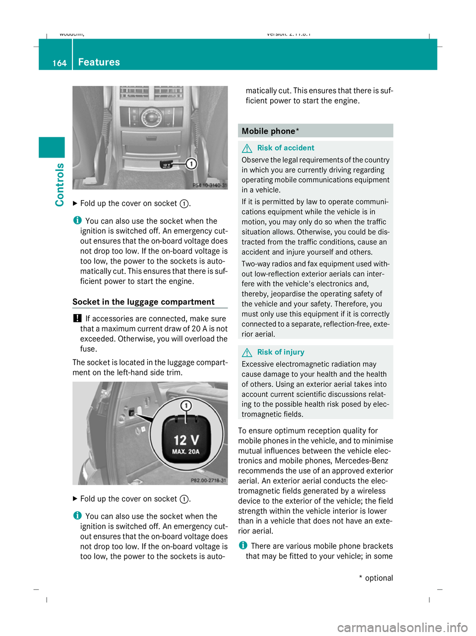
Fold up the cover on socket :.
i You can also use the socket when the
ignition is switched off. An emergency cut-
out ensures that the on-board voltage does
not drop too low. If the on-board voltage is
too low, the power to the sockets is auto-
matically cut. This ensures that there is suf-
ficient power to start the engine.
Socket in the luggage compartment !
If accessories are connected, make sure
that a maximum current draw of 20 A is not
exceeded. Otherwise, you will overload the
fuse.
The socket is located in the luggage compart-
ment on the left-hand side trim. X
Fold up the cover on socket :.
i You can also use the socket when the
ignition is switched off. An emergency cut-
out ensures that the on-board voltage does
not drop too low. If the on-board voltage is
too low, the power to the sockets is auto- matically cut. This ensures that there is suf-
ficient power to start the engine. Mobile phone*
G
Risk of accident
Observe the legal requirements of the country
in which you are currently driving regarding
operating mobile communications equipment
in a vehicle.
If it is permitted by law to operate communi-
cations equipment while the vehicle is in
motion, you may only do so when the traffic
situation allows. Otherwise, you could be dis-
tracted from the traffic conditions, cause an
accident and injure yourself and others.
Two-way radios and fax equipment used with-
out low-reflection exterior aerials can inter-
fere with the vehicle's electronics and,
thereby, jeopardise the operating safety of
the vehicle and your safety. Therefore, you
must only use this equipment if it is correctly
connected to a separate, reflection-free, exte-
rior aerial. G
Risk of injury
Excessive electromagnetic radiation may
cause damage to your health and the health
of others. Using an exterior aerial takes into
account current scientific discussions relat-
ing to the possible health risk posed by elec-
tromagnetic fields.
To ensure optimum reception quality for
mobile phones in the vehicle, and to minimise
mutual influences between the vehicle elec-
tronics and mobile phones, Mercedes-Benz
recommends the use of an approved exterior
aerial. An exterior aerial conducts the elec-
tromagnetic fields generated by a wireless
device to the exterior of the vehicle; the field
strength within the vehicle interior is lower
than in a vehicle that does not have an exte-
rior aerial.
i There are various mobile phone brackets
that may be fitted to your vehicle; in some 164
FeaturesControls
* optional
X164_AKB; 2; 3, en-GB
wobuchh
,V ersion: 2.11.8.1
2009-03-31T14:14:58+02:00 - Seite 164
Dateiname: 6515431202_buchblock.pdf; erzeugt am 01. Apr 2009 00:17:42; WK
Page 168 of 309
cases, these are country-specific. You can
obtain these mobile phone brackets from a
qualified specialist workshop, e.g. a
Mercedes-Benz Service Centre.
The functions and services available when
you use the phone depend on your mobile
phone model and service provider.
Inserting the mobile phone
X Open the telephone compartment
(Y page 153).
X Place the mobile phone bracket into the
pre-installed fitting; see the separate
mobile phone bracket fitting instructions.
X Insert the mobile phone into the mobile
phone bracket; see the separate mobile
phone bracket fitting instructions.
If the mobile phone is inserted in the mobile
phone bracket, you can speak to the person
you are calling using the hands-free system.
You can operate the telephone using the
6 and~ buttons on the multi-function
steering wheel. You can operate other mobile
phone functions via the on-board computer
(Y page 111).
When you take the key out of the ignition lock,
the mobile phone stays on but you can no
longer use the hands-free system.
If you are making a call and you would like to
take the key out of the ignition lock, first
remove the mobile phone from the bracket.
Otherwise, the call will be ended. Garage door opener*
The remote control integrated in the rear-view
mirror allows you to operate up to three dif-
ferent door and gate systems.
i The garage door opener is only available
for certain countries. Observe the legal
requirements in all countries concerned.
The HomeLink ®
garage door opener is
compatible with most European garage and
gate opener drives. More information on HomeLink
®
and/or compatible products is
available from:
R any Mercedes-Benz Service Centre
R the HomeLink ®
hotline
(0) 08000 466 354 65 (free of charge) or
+49 (0) 6838 907-277 (charges apply)
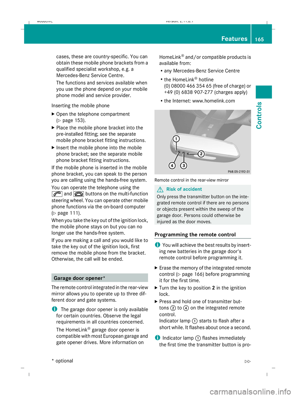
R the Internet: www.homelink.com Remote control in the rear-view mirror
G
Risk of accident
Only press the transmitter button on the inte-
grated remote control if there are no persons
or objects present within the sweep of the
garage door. Persons could otherwise be
injured as the door moves.
Programming the remote control i
You will achieve the best results by insert-
ing new batteries in the garage door's
remote control before programming it.
X Erase the memory of the integrated remote
control ( Ypage 166) before programming
it for the first time.
X Turn the key to position 2in the ignition
lock.
X Press and hold one of transmitter but-
tons ;to? on the integrated remote
control.
Indicator lamp :starts to flash after a
short while. It flashes about once a second.
i Indicator lamp :flashes immediately
the first time the transmitter button is pro- Features
165Controls
* optional
X164_AKB; 2; 3, en-GB
wobuchh,
Version: 2.11.8.1 2009-03-31T14:14:58+02:00 - Seite 165 Z
Dateiname: 6515431202_buchblock.pdf; erzeugt am 01. Apr 2009 00:17:43; WK
Page 169 of 309
grammed. If this transmitter button has
already been programmed, indicator
lamp
:will only start flashing at a rate of
once a second after 20 seconds have
elapsed.
X Keep the transmitter buttons depressed.
X Point the garage door's remote control with
the transmitter towards the left-hand side
of the rear-view mirror from a distance of 5
to 20 cm.
i The distance between the garage door's
remote control and the integrated garage
door opener depends on the system of the
garage door drive. You might require sev-
eral attempts. You should test every posi-
tion for at least 20 seconds before trying
another position.
X Keep the transmitter button on the garage
door's remote control depressed until indi-
cator lamp :starts to flash rapidly.
The programming was successful if indica-
tor lamp :flashes rapidly.
X Release the transmitter buttons on the
garage door's remote control and the inte-
grated remote control.
If indicator lamp :goes out after approx-
imately 20 seconds and did not flash rapidly
before this:
X Release the transmitter buttons on the
integrated and portable remote controls.
X Repeat the programming procedure. When
doing so, change the distance between the
garage door's remote control and the trans-
mitter buttons in the rear-view mirror.
i If the garage door system works with a
rolling code, after programming you must
synchronise the remote control integrated
in the rear-view mirror with the garage door
system receiver.
You will find further information in the
garage door opening system's operating
instructions, e.g. the sections on "Synchro-
nising the transmitter" or "Registering a new transmitter". You can also call the hot-
line mentioned above.
Opening or closing the garage door Once programmed, the integrated remote
control will assume the function of the garage
door system's remote control. Please read
the operating instructions for the garage door
system.
X
Turn the key to position 2in the ignition
lock.
X Press the transmitter button on the rear-
view mirror that you have programmed to
operate the garage door.
Garage door system with fixed code: indi-
cator lamp :lights up continuously.
Garage door system with rolling code: indi-
cator lamp :flashes briefly and then lights
up for approximately two seconds. This is
repeated for up to 20 seconds.
i The transmitter will transmit a signal for
as long as the transmitter button is being
pressed. The transmission will be halted
after a maximum of 20 seconds and indi-
cator lamp :will flash. Press the trans-
mitter button again, if necessary.
Clearing the remote control memory X
Turn the key to position 2in the ignition
lock.
X Press and hold transmitter buttons ;
and ?for approximately 20 seconds until
indicator lamp :flashes rapidly.
The memory is cleared.
i You should clear the remote control mem-
ory before selling the vehicle. Compass*
In the Off-road menu* (Y page 102), the
compass displays the compass bearing of
your direction of travel. You will see N,NE, E,
SE, S,SW, Wor NW in the multi-function display. 166
FeaturesControls
* optional
X164_AKB; 2; 3, en-GB
wobuchh,
Version: 2.11.8.1 2009-03-31T14:14:58+02:00 - Seite 166
Dateiname: 6515431202_buchblock.pdf; erzeugt am 01. Apr 2009 00:17:43; WK
Page 170 of 309
To obtain an accurate display of your com-
pass bearing, the correct geographical zone
must be set. If necessary, the compass must
also be calibrated (Y page 167).
If the compass is not calibrated or is malfunc-
tioning due to external interference, you will
see the Compass – – – message in the dis-
play.
i Large buildings, bridges, power lines or
large transmitting masts as well as metallic objects in or on the vehicle may interfere
with the compass display.
Setting the compass* X
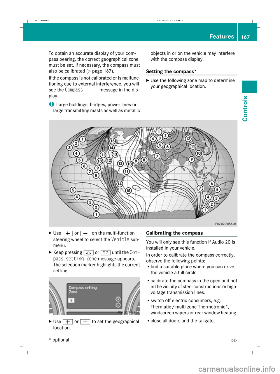
Use the following zone map to determine
your geographical location. X
Use W orX on the multi-function
steering wheel to select the Vehiclesub-
menu.
X Keep pressing &or* until the Com‐
pass setting Zone message appears.
The selection marker highlights the current
setting. X
Use W orX to set the geographical
location. Calibrating the compass You will only see this function if Audio 20 is
installed in your vehicle.
In order to calibrate the compass correctly,
observe the following points:
R
find a suitable place where you can drive
the vehicle a full circle.
R calibrate the compass in the open and not
in the vicinity of steel constructions or high-
voltage transmission lines.
R switch off electric consumers, e.g.
Thermatic /multi-zone Thermotronic*,
windscreen wipers or rear window heating.
R close all doors and the tailgate. Features
167Controls
* optional
X164_AKB; 2; 3, en-GB
wobuchh,
Version: 2.11.8.1 2009-03-31T14:14:58+02:00 - Seite 167 Z
Dateiname: 6515431202_buchblock.pdf; erzeugt am 01. Apr 2009 00:17:43; WK
Page 171 of 309
X
Start the engine.
X Use W orX on the multi-function
steering wheel to select the Vehiclesub-
menu.
X Keep pressing &or* until the Com‐
pass calibration message appears.
The selection marker highlights switched
off . X
Use W orX to select Start.
In the multi-function display, you will see
the Compass calibration active
Please drive a full circle message.
X Drive the vehicle a full circle at approx-
imately 5 – 10 km/h.
When calibration is completed, you will see
the following message in the multi-function
display: Compass calibration Comple‐
ted successfully
If you do not see the Compass calibration
Completed successfully message in the
multi-function display, drive another full cir-
cle. If calibration is not successful within
three minutes of it starting, the Compass
calibration message will appear in the
multi-function display again. This means that
compass calibration is impossible because of
external interference. Repeat calibration at
another location. Floormat* on the driver's side
G
Risk of accident
Make sure that there is sufficient clearance
around the pedals when floormats are used,
and that the floormats are properly secured.
The floormats must be correctly secured at all
times using retainers and press-studs. Before you drive off, check the floormats and
secure if necessary. A floormat which is not
properly secured can slip and, thereby, inter-
fere with the movement of the pedals.
Do not place floormats on top of one another.
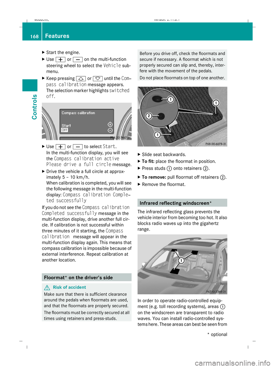
X
Slide seat backwards.
X To fit: place the floormat in position.
X Press studs :onto retainers ;.
X To remove: pull floormat off retainers ;.
X Remove the floormat. Infrared reflecting windscreen*
The infrared reflecting glass prevents the
vehicle interior from becoming too hot. It also
blocks radio waves up into the gigahertz
range. In order to operate radio-controlled equip-
ment (e.g. toll recording systems), areas :
on the windscreen are transparent to radio
waves. You can install radio-controlled sys-
tems here. These areas can best be seen from 168
FeaturesControls
* optional
X164_AKB; 2; 3, en-GB
wobuchh,
Version: 2.11.8.1 2009-03-31T14:14:58+02:00 - Seite 168
Dateiname: 6515431202_buchblock.pdf; erzeugt am 01. Apr 2009 00:17:44; WK