2009 MERCEDES-BENZ E-CLASS ESTATE ignition
[x] Cancel search: ignitionPage 190 of 373
feature, it opens again slightly. The rain
closing feature is then deactivated.
The panorama sliding sunroof does not close
if:
R it is raised at the rear.
R it is blocked.
R no rain is falling on the area of the wind-
screen being monitored by the rain sensor
(e.g. because the vehicle is under a bridge
or in a carport). Roller sunblinds for the panorama
sliding sunroof*
The roller sunblinds provide protection from
the sun. The two roller sunblinds can only be
opened and closed together when the pano-
rama sliding sunroof is closed. G
Risk of injury
Make sure that nobody can become trapped
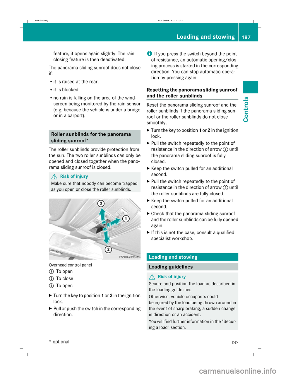
as you open or close the roller sunblinds. Overhead control panel
: To open
; To close
= To open
X Turn the key to position 1or 2in the ignition
lock.
X Pull or push the switch in the corresponding
direction. i
If you press the switch beyond the point
of resistance, an automatic opening/clos-
ing process is started in the corresponding
direction. You can stop automatic opera-
tion by pressing again.
Resetting the panorama sliding sunroof
and the roller sunblinds Reset the panorama sliding sunroof and the
roller sunblinds if the panorama sliding sun-
roof or the roller sunblinds do not close
smoothly.
X Turn the key to position 1or 2in the ignition
lock.
X Pull the switch repeatedly to the point of
resistance in the direction of arrow ;until
the panorama sliding sunroof is fully
closed.
X Keep the switch pulled for an additional
second.
X Pull the switch repeatedly to the point of
resistance in the direction of arrow ;until
the roller sunblinds are fully closed.
X Keep the switch pulled for an additional
second.
X Check that the panorama sliding sunroof
and the roller sunblinds can be fully opened
again.
X If this is not the case, consult a qualified
specialist workshop. Loading and stowing
Loading guidelines
G
Risk of injury
Secure and position the load as described in
the loading guidelines.
Otherwise, vehicle occupants could
be injured by the load being thrown around in
the event of sharp braking, a sudden change
in direction or an accident.
You will find further information in the "Secur-
ing a load" section. Loading and stowing
187Controls
* optional
212_AKB; 2; 4, en-GB
mkalafa,
Version: 2.11.8.1 2009-05-05T14:17:16+02:00 - Seite 187 Z
Dateiname: 6515346702_buchblock.pdf; erzeugt am 07. May 2009 14:16:33; WK
Page 212 of 373
X
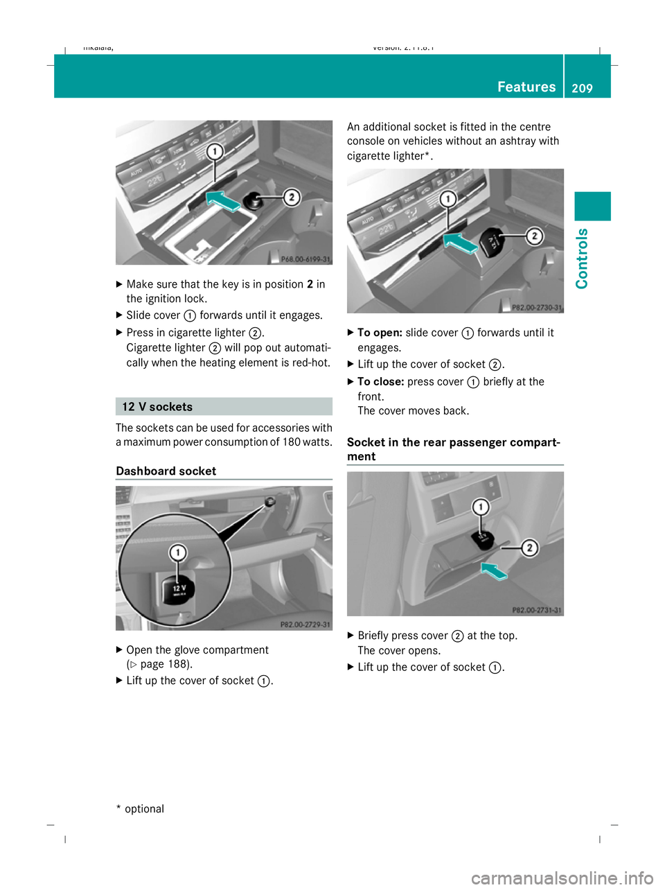
Make sure that the key is in position 2in
the ignition lock.
X Slide cover :forwards until it engages.
X Press in cigarette lighter ;.
Cigarette lighter ;will pop out automati-
cally when the heating element is red-hot. 12 V sockets
The sockets can be used for accessories with
a maximum power consumption of 180 watts.
Dashboard socket X
Open the glove compartment
(Y page 188).
X Lift up the cover of socket :.An additional socket is fitted in the centre
console on vehicles without an ashtray with
cigarette lighter*. X
To open: slide cover :forwards until it
engages.
X Lift up the cover of socket ;.
X To close: press cover :briefly at the
front.
The cover moves back.
Socket in the rear passenger compart-
ment X
Briefly press cover ;at the top.
The cover opens.
X Lift up the cover of socket :. Features
209Controls
* optional
212_AKB; 2; 4, en-GB
mkalafa,
Version: 2.11.8.1 2009-05-05T14:17:16+02:00 - Seite 209 Z
Dateiname: 6515346702_buchblock.pdf; erzeugt am 07. May 2009 14:16:51; WK
Page 214 of 373
When you take the key out of the ignition lock,
the mobile phone stays on but you can no
longer use the hands-free system.
If you are making a call and you would like to
take the key out of the ignition lock, first
remove the mobile phone from the bracket.
Otherwise, the call will be ended.
Sliding adapter for the mobile phone
bracket (automatic vehicles with
DIRECT SELECT selector lever*) Certain mobile phone brackets require a slid-
ing adapter so the bracket can be installed
correctly.
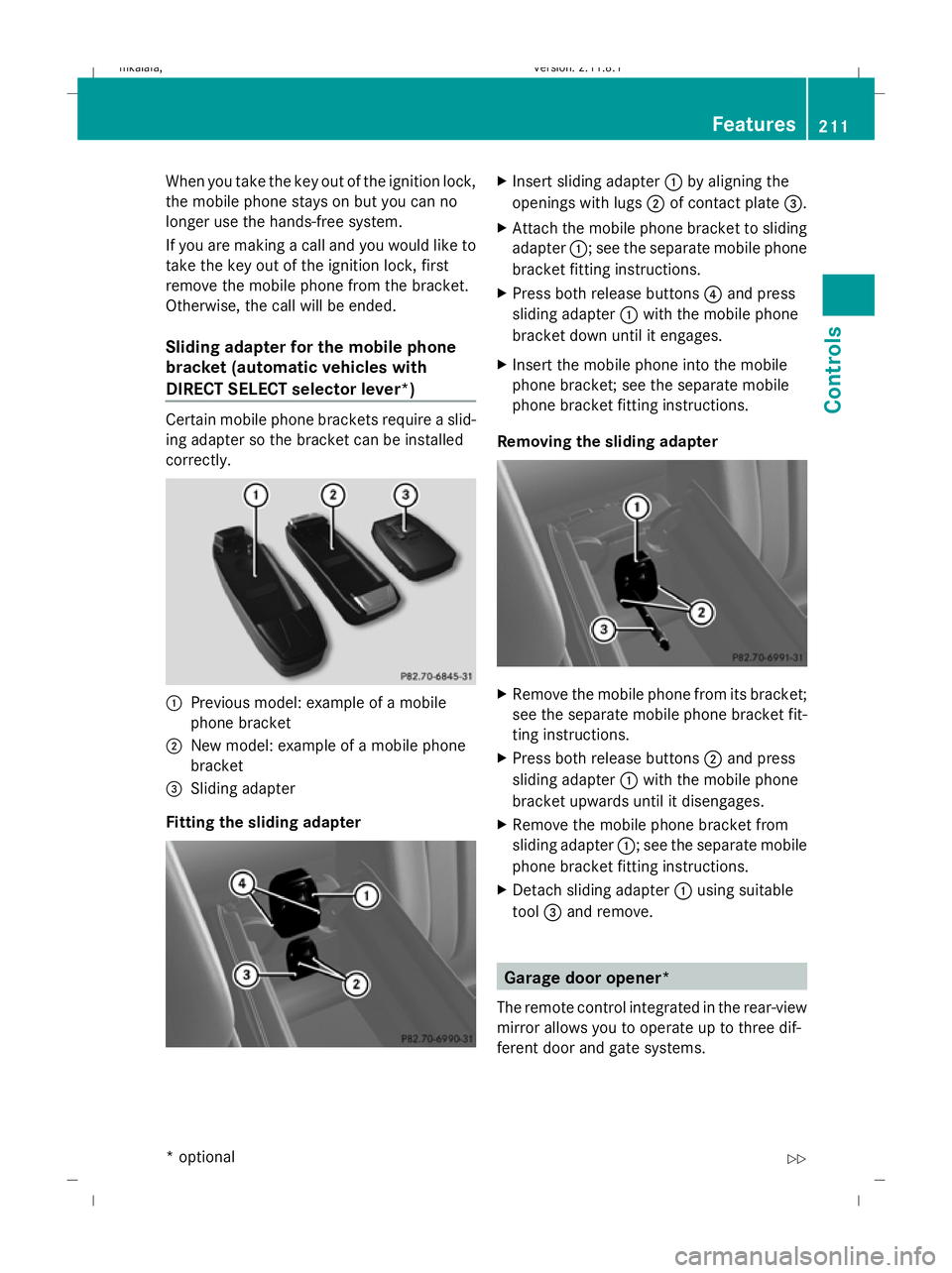
:
Previous model: example of a mobile
phone bracket
; New model: example of a mobile phone
bracket
= Sliding adapter
Fitting the sliding adapter X
Insert sliding adapter :by aligning the
openings with lugs ;of contact plate =.
X Attach the mobile phone bracket to sliding
adapter :; see the separate mobile phone
bracket fitting instructions.
X Press both release buttons 4and press
sliding adapter :with the mobile phone
bracket down until it engages.
X Insert the mobile phone into the mobile
phone bracket; see the separate mobile
phone bracket fitting instructions.
Removing the sliding adapter X
Remove the mobile phone from its bracket;
see the separate mobile phone bracket fit-
ting instructions.
X Press both release buttons ;and press
sliding adapter :with the mobile phone
bracket upwards until it disengages.
X Remove the mobile phone bracket from
sliding adapter :; see the separate mobile
phone bracket fitting instructions.
X Detach sliding adapter :using suitable
tool =and remove. Garage door opener*
The remote control integrated in the rear-view
mirror allows you to operate up to three dif-
ferent door and gate systems. Features
211Controls
* optional
212_AKB; 2; 4, en-GB
mkalafa,
Version: 2.11.8.1 2009-05-05T14:17:16+02:00 - Seite 211 Z
Dateiname: 6515346702_buchblock.pdf; erzeugt am 07. May 2009 14:16:52; WK
Page 215 of 373
i
The garage door opener is only available
for certain countries. Observe the legal
requirements in all countries concerned.
The HomeLink ®
garage door opener is
compatible with most European garage and
gate opener drives. More information on
HomeLink ®
and/or compatible products is
available from:
R any Mercedes-Benz Service Centre
R the HomeLink ®
hotline
(0) 08000 466 354 65 (free of charge) or
+49 (0) 6838 907-277 (charges apply)
R the Internet: www.homelink.com G
Risk of accident
Only press the transmitter button on the inte-
grated remote control if there are no persons
or objects present within the sweep of the
garage door. Persons could otherwise be
injured as the door moves.
Programming the remote control i
You will achieve the best results by insert-
ing new batteries in the garage door's
remote control before programming it.
X Erase the memory of the integrated remote
control (Y page 213) before programming
it for the first time.
X Turn the key to position 2in the ignition
lock. X
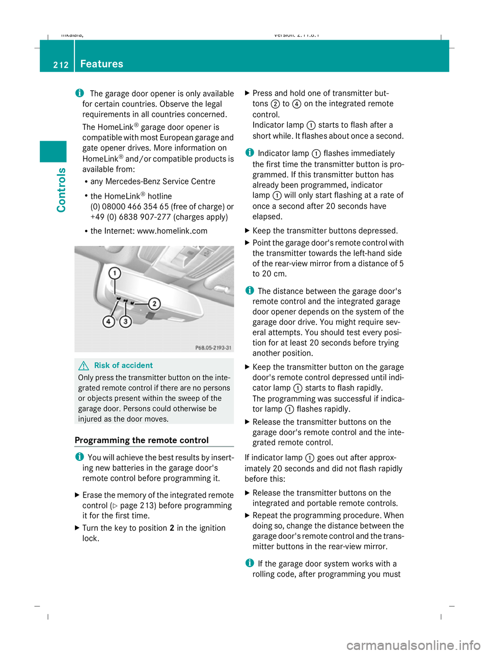
Press and hold one of transmitter but-
tons ;to? on the integrated remote
control.
Indicator lamp :starts to flash after a
short while. It flashes about once a second.
i Indicator lamp :flashes immediately
the first time the transmitter button is pro-
grammed. If this transmitter button has
already been programmed, indicator
lamp :will only start flashing at a rate of
once a second after 20 seconds have
elapsed.
X Keep the transmitter buttons depressed.
X Point the garage door's remote control with
the transmitter towards the left-hand side
of the rear-view mirror from a distance of 5
to 20 cm.
i The distance between the garage door's
remote control and the integrated garage
door opener depends on the system of the
garage door drive. You might require sev-
eral attempts. You should test every posi-
tion for at least 20 seconds before trying
another position.
X Keep the transmitter button on the garage
door's remote control depressed until indi-
cator lamp :starts to flash rapidly.
The programming was successful if indica-
tor lamp :flashes rapidly.
X Release the transmitter buttons on the
garage door's remote control and the inte-
grated remote control.
If indicator lamp :goes out after approx-
imately 20 seconds and did not flash rapidly
before this:
X Release the transmitter buttons on the
integrated and portable remote controls.
X Repeat the programming procedure. When
doing so, change the distance between the
garage door's remote control and the trans-
mitter buttons in the rear-view mirror.
i If the garage door system works with a
rolling code, after programming you must 212
FeaturesControls
212_AKB; 2; 4, en-GB
mkalafa,
Version: 2.11.8.1 2009-05-05T14:17:16+02:00 - Seite 212
Dateiname: 6515346702_buchblock.pdf; erzeugt am 07. May 2009 14:16:52; WK
Page 216 of 373
synchronise the remote control integrated
in the rear-view mirror with the garage door
system receiver.
You will find further information in the
garage door opening system's operating
instructions, e.g. the sections on "Synchro-
nising the transmitter" or "Registering a
new transmitter". You can also call the hot-
line mentioned above.
Opening or closing the garage door Once programmed, the integrated remote
control will assume the function of the garage
door system's remote control. Please read
the operating instructions for the garage door
system.
X Turn the key to position 2in the ignition
lock.
X Press the transmitter button on the rear-
view mirror that you have programmed to
operate the garage door.
Garage door system with fixed code: indi-
cator lamp :lights up continuously.
Garage door system with rolling code: indi-
cator lamp :flashes briefly and then lights
up for approximately two seconds. This is
repeated for up to 20 seconds.
i The transmitter will transmit a signal for
as long as the transmitter button is being
pressed. The transmission will be halted
after a maximum of 20 seconds and indi-
cator lamp :will flash. Press the trans-
mitter button again, if necessary.
Clearing the remote control memory X
Turn the key to position 2in the ignition
lock.
X Press and hold transmitter buttons ;
and ?for approximately 20 seconds until
indicator lamp :flashes rapidly.
The memory is cleared.
i You should clear the remote control mem-
ory before selling the vehicle. Floormat* on the driver's side
G
Risk of accident
Make sure that there is sufficient clearance
around the pedals when floormats are used,
and that the floormats are properly secured.
The floormats must be correctly secured at all
times using retainers and press-studs.
Before you drive off, check the floormats and
secure if necessary. A floormat which is not
properly secured can slip and, thereby, inter-
fere with the movement of the pedals.
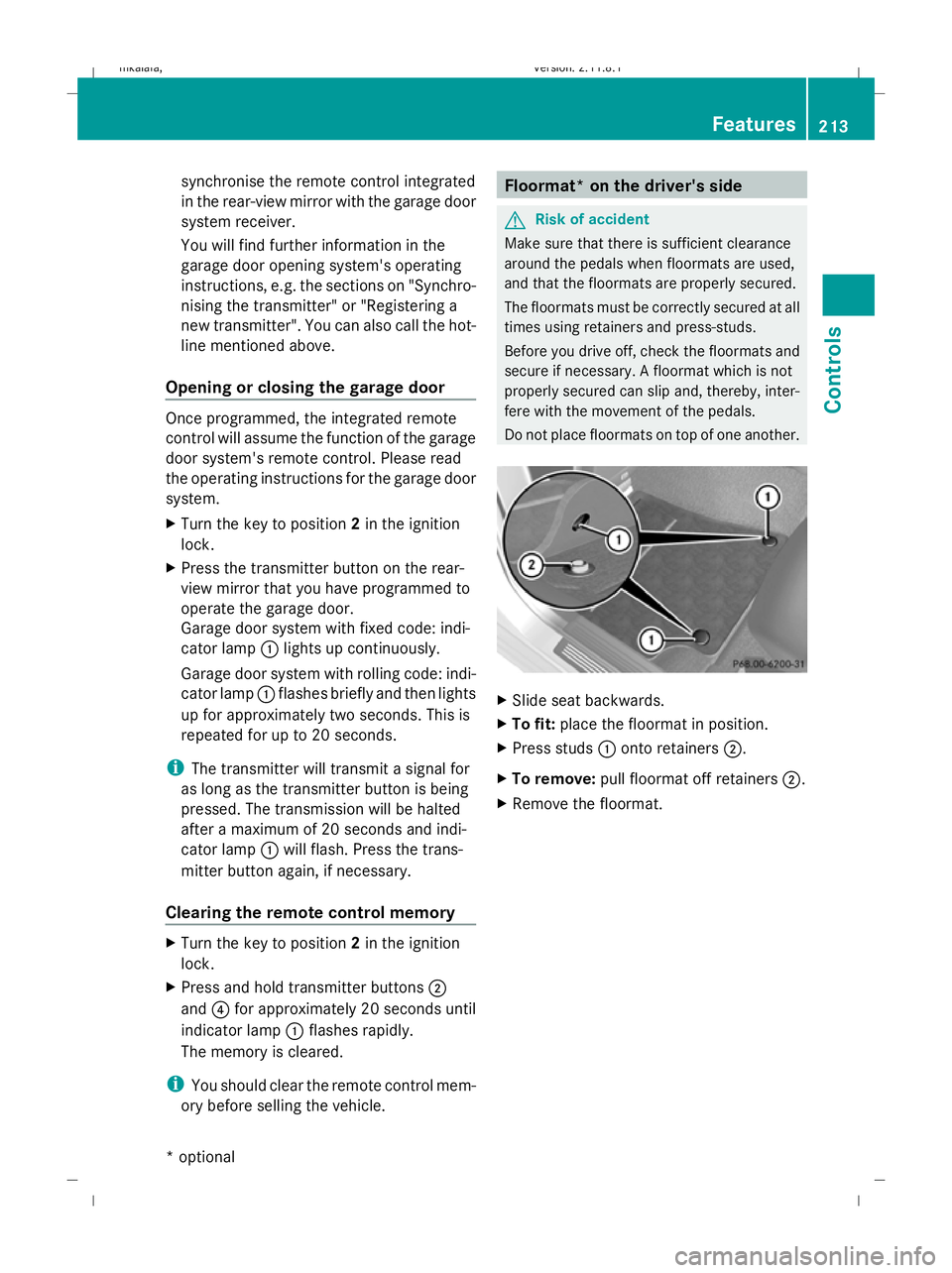
Do not place floormats on top of one another. X
Slide seat backwards.
X To fit: place the floormat in position.
X Press studs :onto retainers ;.
X To remove: pull floormat off retainers ;.
X Remove the floormat. Features
213Controls
* optional
212_AKB; 2; 4, en-GB
mkalafa,
Version: 2.11.8.1 2009-05-05T14:17:16+02:00 - Seite 213 Z
Dateiname: 6515346702_buchblock.pdf; erzeugt am 07. May 2009 14:16:52; WK
Page 222 of 373
with the climatic specifications of standard
EN 590 can help to prevent operating prob-
lems. If the ambient temperature is unusually
low or if you use fuel that has not been adap-
ted to the climatic specifications (e.g. diesel
fuel from the Mediterranean area), the flow
properties of the fuel may be inadequate.
Flow improver
Flow improvers can be added to improve the
cold resistance of diesel fuel. The effective-
ness of a flow improver is not guaranteed with
every fuel.
Correct dosage and thorough mixing are deci-
sive factors in ensuring improvement in low-
temperature resistance. Under certain cir-
cumstances, an excessive dosage may
actually decrease low-temperature resist-
ance and should therefore be avoided (follow
the manufacturer's dosing instructions).
Mix the additive with the diesel in good time,
before the flow properties of the diesel
become inadequate. Otherwise, malfunctions
can only be rectified by heating the entire fuel
system, e.g. by parking the vehicle in a heated
garage.
Observe the information provided by the man-
ufacturer when using a flow improver. Only
use flow improvers that have been tested and
approved by Mercedes-Benz. You can obtain
further information from any Mercedes-Benz
Service Centre. Engine compartment
Bonnet
G
Risk of accident
Do not pull the release lever while the vehicle
is in motion. The bonnet may otherwise open
and block your view.
Active bonnet (pedestrian protection) The active bonnet can reduce the risk of injury
to pedestrians in certain accident situations.
Raising the bonnet increases the clearance to hard components, such as the engine. Fur-
ther information about the active bonnet
(Y
page 302).
Opening G
Risk of injury
There is a risk of injury if the bonnet is open,
even if the engine is not running.
Some engine components can become very
hot.
To avoid the risk of burns, only touch those
components described in the Operating
Instructions and observe the relevant safety
notes. G
Risk of injury
The radiator fan between the radiator and the
engine can start automatically, even if the key
has been removed from the ignition lock.
Keep away from the area of rotation of the fan
blades. Otherwise you could be injured.
Vehicles with a petrol engine:
The electronic ignition system uses high volt-
age. For this reason, you must never touch the
ignition system components (ignition coil,
ignition cable, spark plug connector or test
socket) while:
R the engine is running
R the engine is being started
R the ignition is switched on and the engine
is being cranked by hand
You could otherwise receive an electric shock
and be severely or fatally injured.
Vehicles with a diesel engine:
the electronic injector control operates at
high voltage. For this reason, you must never
touch injection system components while:
R the engine is running
R the engine is being started
R the ignition is switched on
You could otherwise receive an electric shock
and be severely or fatally injured. Engine compartment
219Operation
212_AKB; 2; 4, en-GB
mkalafa, Version: 2.11.8.1 2009-05-05T14:17:16+02:00 - Seite 219 Z
Dateiname: 6515346702_buchblock.pdf; erzeugt am 07. May 2009 14:16:54; WK
Page 223 of 373
X
Make sure that the windscreen wipers are
switched off. G
Risk of injury
The windscreen wipers and wiper linkage
could be set in motion.
When the bonnet is open, you or others could
be injured by the wiper linkage.
Make sure that the windscreen wiper is
switched off. Remove the key or make sure
that no ignition level has been selected on
KEYLESS GO*. In the instrument cluster, all of
the indicator lamps must be out.
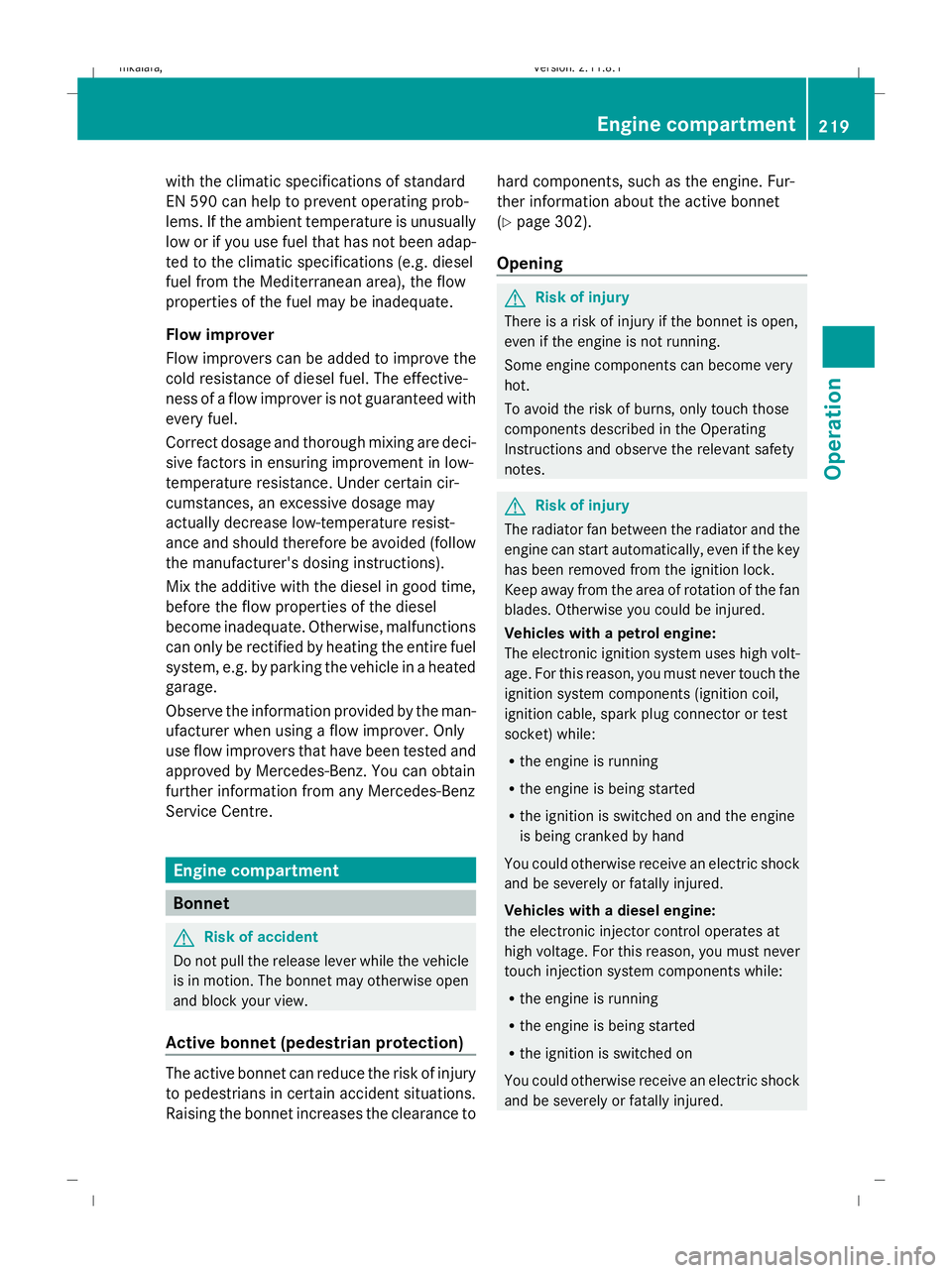
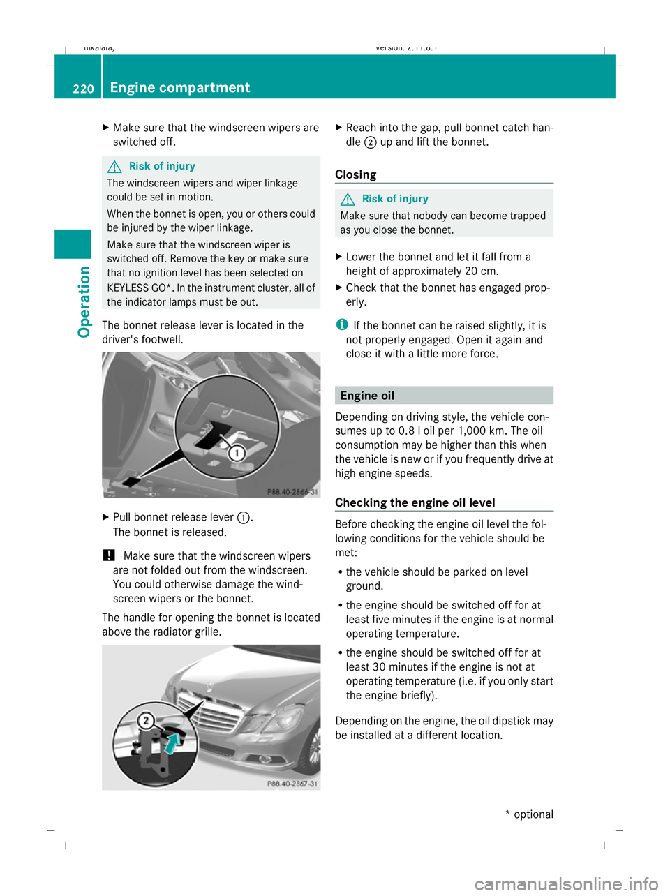
The bonnet release lever is located in the
driver's footwell. X
Pull bonnet release lever :.
The bonnet is released.
! Make sure that the windscreen wipers
are not folded out from the windscreen.
You could otherwise damage the wind-
screen wipers or the bonnet.
The handle for opening the bonnet is located
above the radiator grille. X
Reach into the gap, pull bonnet catch han-
dle ;up and lift the bonnet.
Closing G
Risk of injury
Make sure that nobody can become trapped
as you close the bonnet.
X Lower the bonnet and let it fall from a
height of approximately 20 cm.
X Check that the bonnet has engaged prop-
erly.
i If the bonnet can be raised slightly, it is
not properly engaged. Open it again and
close it with a little more force. Engine oil
Depending on driving style, the vehicle con-
sumes up to 0.8 l oil per 1,000 km. The oil
consumption may be higher than this when
the vehicle is new or if you frequently drive at
high engine speeds.
Checking the engine oil level Before checking the engine oil level the fol-
lowing conditions for the vehicle should be
met:
R the vehicle should be parked on level
ground.
R the engine should be switched off for at
least five minutes if the engine is at normal
operating temperature.
R the engine should be switched off for at
least 30 minutes if the engine is not at
operating temperature (i.e. if you only start
the engine briefly).
Depending on the engine, the oil dipstick may
be installed at a different location. 220
Engine compartmentOperation
* optional
212_AKB; 2; 4, en-GB
mkalafa,
Version: 2.11.8.1 2009-05-05T14:17:16+02:00 - Seite 220
Dateiname: 6515346702_buchblock.pdf; erzeugt am 07. May 2009 14:16:55; WK
Page 224 of 373
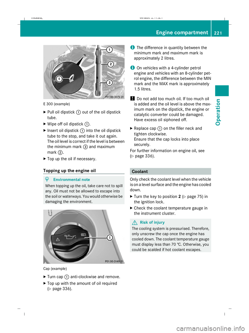
E 300 (example)
X
Pull oil dipstick :out of the oil dipstick
tube.
X Wipe off oil dipstick :.
X Insert oil dipstick :into the oil dipstick
tube to the stop, and take it out again.
The oil level is correct if the level is between
the minimum mark =and maximum
mark ;.
X Top up the oil if necessary.
Topping up the engine oil H
Environmental note
When topping up the oil, take care not to spill
any. Oil must not be allowed to escape into
the soil or waterways. You would otherwise be
damaging the environment. Cap (example)
X
Turn cap :anti-clockwise and remove.
X Top up with the amount of oil required
(Y page 336). i
The difference in quantity between the
minimum mark and maximum mark is
approximately 2 litres.
i On vehicles with a 4-cylinder petrol
engine and vehicles with an 8-cylinder pet-
rol engine, the difference between the MIN
mark and the MAX mark is approximately
1.5 litres.
! Do not add too much oil. If too much oil
is added and the oil level is above the max-
imum mark on the dipstick, the engine or
catalytic converter could be damaged.
Have excess oil siphoned off.
X Replace cap :on the filler neck and
tighten clockwise.
Ensure that the cap locks into place
securely.
For further information on engine oil, see
(Y page 336). Coolant
Only check the coolant level when the vehicle
is on a level surface and the engine has cooled
down.
X Turn the key to position 2(Y page 75) in
the ignition lock.
X Check the coolant temperature gauge in
the instrument cluster. G
Risk of injury
The cooling system is pressurised. Therefore,
only unscrew the cap once the engine has
cooled down. The coolant temperature gauge
must display less than 70 †. Otherwise, you
could be scalded if hot coolant escapes. Engine compartment
221Operation
212_AKB; 2; 4, en-GB
mkalafa, Version: 2.11.8.1 2009-05-05T14:17:16+02:00 - Seite 221 Z
Dateiname: 6515346702_buchblock.pdf; erzeugt am 07. May 2009 14:16:56; WK