2009 MERCEDES-BENZ E-CLASS COUPE clock
[x] Cancel search: clockPage 196 of 313
countries. Whe
nusing symmetrical lights, the
edg eoft he carriageway is not illuminated as
widel yand as far ahea dasnormal.
On vehicle swithI ntelligent Light System*,
yo uc an switch the headlamp susing the "Tou-
ris tm ode" function in the on-board computer
(Y page 119).
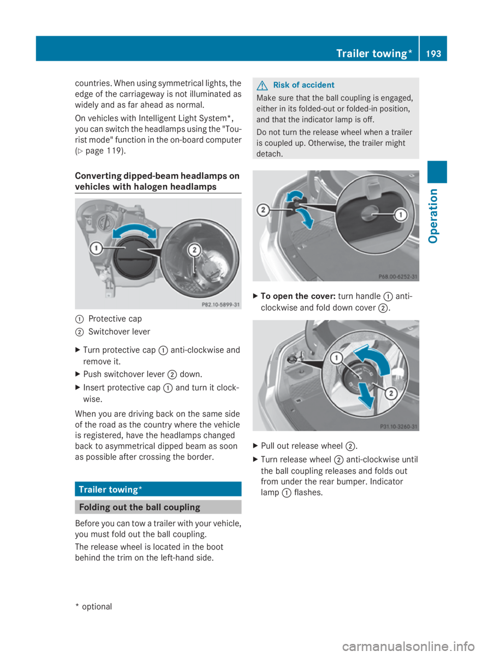
Converting dipped-beam headlamps on
vehicle swithh aloge nheadlamps 0046
Protective cap
0047 Switchove rlev er
X Turn protective cap 0046anti-clockwise and
remove it.
X Push switchove rlev er 0047 down.
X Inser tprotective cap 0046and turn it clock-
wise.
Whe nyou are driving back on the same side
of the roa dasthe country where the vehicle
is registered ,havet he headlamp schanged
back to asymmetrical dippe dbeamass oon
as possible afte rcrossing the border. Trailer towing*
Folding out the bal
lcou pling
Before yo ucan tow atraile rwithy ourvehicle,
yo um ustfoldo utthe ball coupling.
The release wheel is locate dinthe boot
behind the trim on the left-hand side. G
Risk of accident
Make sure that the ball coupling is engaged,
either in its folded-ou torfolded-in position,
and that the indicator lamp is off.
Do not turn the release wheel whe natrailer
is coupled up .Otherwise, the traile rmight
detach. X
To ope nthe cover: turn handle 0046anti-
clockwise and fol ddownc over 0047. X
Pull ou trelease wheel 0047.
X Turn release wheel 0047anti-clockwise until
the ball coupling releases and folds out
from under the rea rbum per. Indicator
lamp 0046flashes. Traile
rtowing* 193Operation
*o
ptional
207_AKB; 2; 3, en-GB
mkalafa
,V ersion: 2.11.8.1
2009-07-23T10:23:49+02:00
-Seite 193 Z
Page 199 of 313
Driving tips
R
Maintai nagreate rdistanc efromt hevehi-
cle in fron ttha nw hen drivin gwithout a
trailer.
R Avoid brakin gabruptly. If possible, brake
gentl yatfirst to allow th etrailer to run on.
Then, increase th ebrakin gforce rapidly.
R The value sgiven fo rgradient-climbing
capabilities from astandstill refer to sea
level. Whe ndrivin ginm ountainous areas,
note that th epowe routput of th eengine,
and consequentl ythe vehicle's gradient-
climbing capability, decreas ewithi ncrea s-
in ga ltitude.
If th etrailer swings from side to side:
X Do no taccelerate.
X Do no tcounter-steer.
X Brake if necessary. G
Risk of accident
On no accoun tshould you attemp ttodraw the
vehicle/trailer combination out by increasing
speed. Folding in th
eballc oupling
i Fold th eball couplin gbackinify ou are
no tu sin gthe trailer to whitch. G
Risk of injury
Mak esuret hatnop ersonsoranimals are in
th ep ivotin grange of th eball coupling. Other-
wise ,the yc ould be injured.
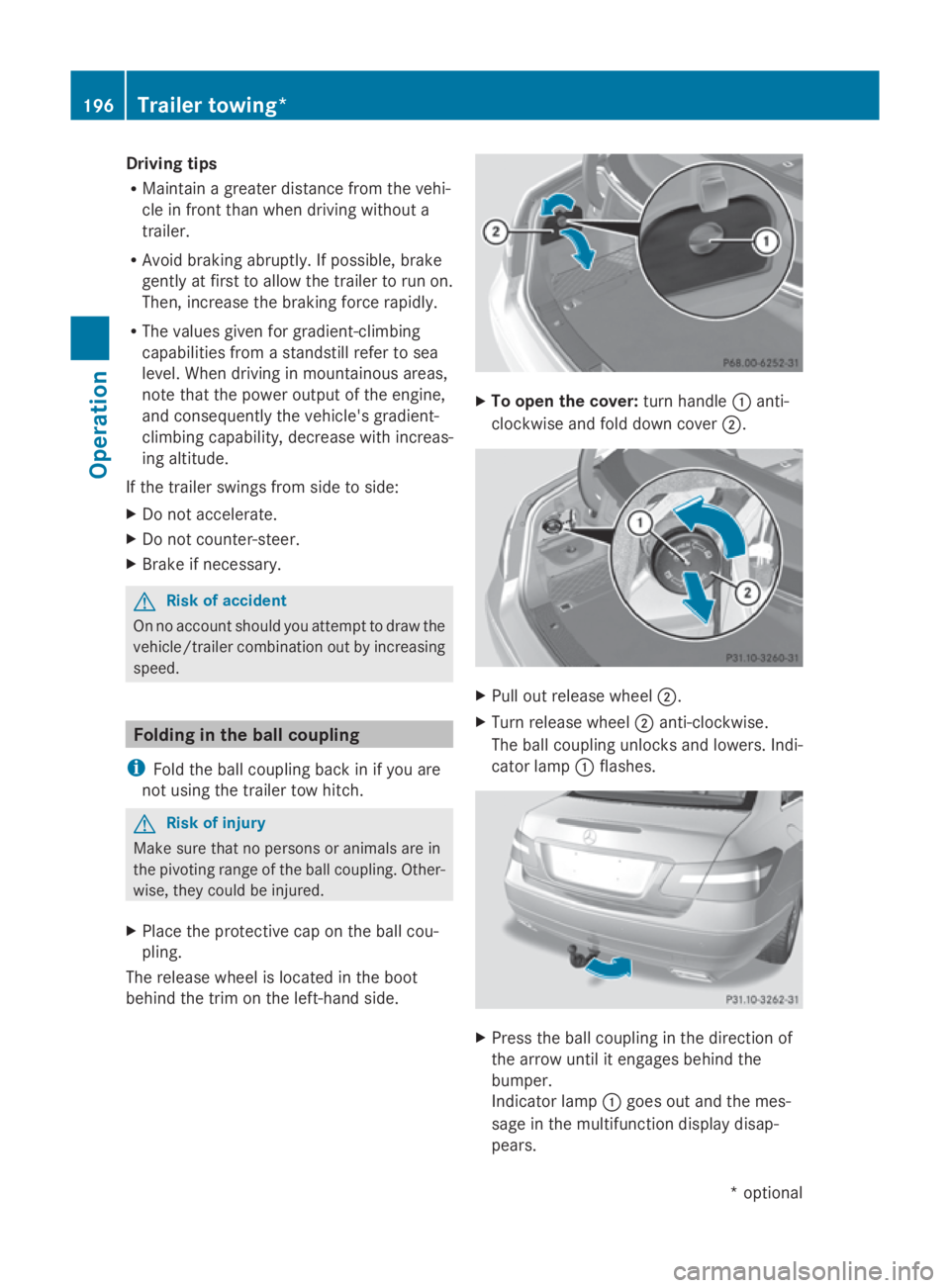
X Plac ethe protective cap on th eball cou-
pling.
The release whee lislocate dintheboot
behin dthe trim on th eleft-han dside. X
To ope nthe cover: turnh andle 0046anti-
clockwise and fold down cover 0047. X
Pull out release wheel 0047.
X Tur nrelease wheel 0047anti-clockwise.
The ball couplin gunlocks and lowers .Ind i-
cator lamp 0046flashes. X
Press th eball couplin ginthedirection of
th ea rrow until it engage sbehin dthe
bumper.
Indicato rlamp 0046goe sout and th emes-
sage in th emultifunction display disap-
pears. 196
Trailer towing*Operation
*optional
207_AKB; 2; 3, en-GB
mkalafa,
Version: 2.11.8.1 2009-07-23T10:23:49+02:00-Seite196
Page 200 of 313

Trailer power supply
When it leaves the factory ,you rv ehicle's
trailer socket outle tise quippe dwithap er-
manent powe rsuppl yand apower supply that
is switched on via the ignition lock.
The permanent powe rsuppl yiss upplie dvia
trailer socket pi n9.
The powe rsuppl ythatiss witched on via the
ignition lock is supplied via trailer socket
pi n1 0.
! Youc an connect consumers with apower
rating of up to 240 Wtothe permanent
powe rsuppl yand up to 180 Wtothe power
supply tha tiss witched on via the ignition
lock.
Yo um ustn ot charge atrailer battery using
the powe rsupply.
The trailer' spermanent powe rsuppl yis
switched off in the event of lo wvehicl esupply
voltag eand after si xhours at the latest.
Yo uc an obtai nfurthe rinformatio nabout
installing the trailer electrics fro maqualified
specialis tworkshop ,e.g.aM ercedes-Benz
Service Centre.
X To switc hthe connected power supply
on or off: turnthe key in the ignition lock
to position 2or 0,r espectively. Bulb failure indicator fo
rLEDs
i If LED lamps ar efitte dint he trailer, an
error message ma yappea rinthe multi-
functio ndisplay –evenift hereisnof ault –
if the corresponding LED chain' scurrent
dra wd rops belo w50milliamperes (mA).
To ensur ereliabl eoperatio noft he bulb failure
indicator, aminimu mcurrent of 50 mA must
be guaranteed by the manufacturer of each
LED chain in the trailer lighting. Trailer with 7-pi
nconnect or
If your trailer ha sa7-pinc onnector, yo ucan
connect it to the 13-pin socket on the ball
coupling using an adapter or, if necessary ,an
adapter cable .Both of these can be obtained
at aq uali fied specialis tworkshop ,e.g.ata
Mercedes-Benz Service Centre.
Fittin gthe adapter X
Open the socket cover.
X Insert connector with lug 0046into
groove 0047on the socket and tur nthe con-
necto rclockwise to the stop.
X Make the cove rengage.
X If yo uareusing an adapter cable ,sec ure
the cable to the trailer with cable ties.
! Make sure tha tthere is sufficient cable
play so tha tthe cable canno tbecome
detached when cornering. Service
ASSYST PLUS service interval display
The ASSYST PLU Sservice interva ldisplay
informs yo uofthe next service du edate.
The service du edateiss hown in the multi-
functio ndisplay ,for example:
Nex tservic eAin..d ays
Nex tservic eAin. .. km
Servic eAdue
The letter indicates which service is due. A
stands for aminor service and Bfor am ajor Service
197Operation
207_AKB; 2; 3, en-GB
mkalafa,V ersion: 2.11.8.1
2009-07-23T10:23:49+02:00
-Seite 197 Z
Page 211 of 313

Vehicles with
a"Minispare "emer-
genc yspare wheel* X
Remove tool kit tray 0047.
X Turn stowag ewell008A anti-clockwise and
remove it.
X Remove "Minispare" emergency spare
wheel 0046. Display messages
Notes
G
Ris
kofa ccident
The on-board compute ronlyr ecords and dis-
play smalfunctions and warning sfrom certain
systems. For thi sreason, yo ushoul dalways
make sure tha tyou rvehicl eiss afetou se.Y ou
could otherwise cause an accident by driving
an unsafe vehicle.
Certai ndisplay messages ar eaccompanied
by aw arning tone or acontinuous tone.
The multi-functio ndisplay shows high-priority
display messages in red.
Please respond in accordance with the dis-
play messages and follo wthe additional
notes in this Owner' sManual. G
Ris
kofa ccident
No further messages can be displayed if the
instrument cluster or the multifunctio ndis-
play fails.
Thi sm eans tha tyou will not see information
abou tthe driving situation, such as the speed, outsid
etemperature ,warning/indicator
lamps ,display messages or system failures.
The vehicle's handling characteristic smaybe
affected. Adjust your driving style and speed
accordingly.
Immediately consult aquali fied specialist
workshop which ha sthe necessary specialist
knowledge and tool stocarry ou tthe work
required .Mercedes-Benz recommends that
yo uu seaM ercedes-Benz Service Centre for
thi sp urpose. In particular, work relevant to
safety or on safety-relate dsystem smustbe
carrie doutataq uali fied specialist workshop.
Whe nyou stop and park the vehicle, please
observe the instructions provided for HOLD
(Y page 135) and parking (Y page 100).
Calling up display messages The on-boar
dcompute rsaves certain display
messages ,which yo ucan cal lup.
X Press 0040or003E on the steering wheel
to select the Servicemenu.
If ther earedisplay messages ,the multi-
functio ndisplay shows ,e.g. 2m essages.
X Using 003Cor003D select the entry ,e.g.
2m essages.
X Confir mwith0064 .
X Using 003Dor003C scroll throug hthe dis-
play messages.
Hiding display messages Yo
uc anno thided isplay messages of the
highest priority. The multi-functio ndisplay
shows thes emessages continuously until
thei rcauses have been remedied.
Use the buttons on the multi-functio nsteer-
ing wheel.
X Use the 0064or0041 button on the steer-
ing whee ltohidet he display message.
The following table scontain al lthe display
messages. 208
Display messagesPractical advice
*o
ptional
207_AKB; 2; 3, en-GB
mkalafa,
Version: 2.11.8.1 2009-07-23T10:23:49+02:00-Seite 208
Page 253 of 313
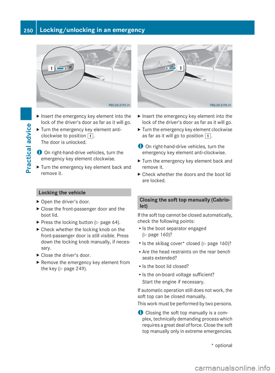
X
Insert the emergency key element into the
lock of the driver's door as far as it willg o.
X Turn the emergency key element anti-
clockwise to position 004A.
The door is unlocked.
i On right-hand-drive vehicles, turn the
emergency key element clockwise.
X Turn the emergency key element back and
remove it. Locking the vehicle
X Open the driver's door.
X Close the front-passenger door and the
boot lid.
X Press the locking button (Y page 64).
X Check whether the locking knob on the
front-passenger door is still visible. Press
down the locking knob manually,ifn eces-
sary.
X Close the driver's door.
X Remove the emergency key element from
the key (Y page 249). X
Insert the emergency key element into the
lock of the driver's door as far as it willg o.
X Turn the emergency key element clockwise
as far as it willgotop osition004A.
i On right-hand-drive vehicles, turn the
emergency key element anti-clockwise.
X Turn the emergency key element back and
remove it.
X Check whether the doors and the boot lid
are locked. Closing the soft top manually (Cabrio-
let)
If the soft top cannot be closed automatically,
check the following points:
R Is the boot separator engaged
(Y page 160)?
R Is the skibag cover* closed (Y page 160)?
R Are the head restraints on the rear bench
seats extended?
R Is the boot lid closed?
R Is the on-board voltage sufficient?
Start the engine if necessary.
If automatic operation still does not work, the
soft top can be closed manually.
This work must be performed by two persons.
i Closing the soft top manually is acom-
plex, technically demanding process which
requires agreat deal of force. Close the soft
top manually only in extreme emergencies. 250
Locking/unlocking in an emergencyPractical advice
*o
ptional
207_AKB; 2; 3, en-GB
mkalafa
,V ersion: 2.11.8.1
2009-07-23T10:23:49+02:00
-Seite 250
Page 254 of 313
In these situations, it is better to get in
touch with
aqualified specialist workshop,
e.g. aMercedes-Benz Service Centre. G
Risk of injury
Remove wristwatches and any jewellery such
as rings or bracelets. You could otherwis eget
caught, injured and damage the vehicle.
Alwaysg rip the soft top at the indicated grip-
ping points when closing the soft top man-
ually. You could otherwis ebeinjured.
X Depress the parking brake.
X Open the side windows.
X Lower the head restraints (automatically:
(Y page 69) or manually:( Ypage 257)).
X Remove the key from the ignition lock.
X Open the boot.
X Take the two straps out of the vehicle tool
kit (Y page 207).
X Take the hex-socket wrench out of the
Owner's Manualw allet and keep it with
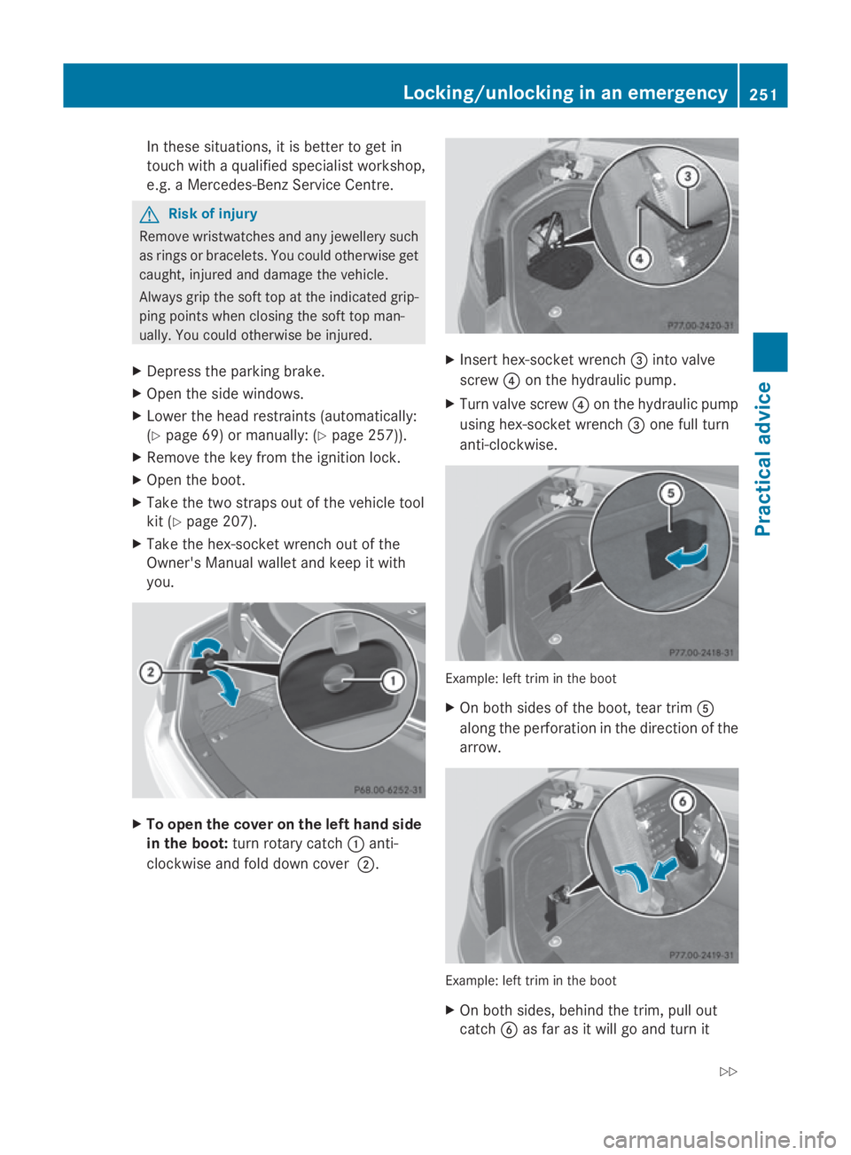
you. X
To open the cover on the left hand side
in the boot: turn rotary catch 0046anti-
clockwise and fold down cover 0047. X
Insert hex-socket wrench 008Ainto valve
screw 0088on the hydraulicp ump.
X Turn valve screw 0088on the hydraulicp ump
using hex-socket wrench 008Aone full turn
anti-clockwise. Example: left trim in the boot
X
On both sides of the boot, tear trim 0086
along the perforatio ninthe direction of the
arrow. Example: left trim in the boot
X
On both sides,b ehind the trim, pullo ut
catch 0087as far as it willgoa nd turn it Locking/unlocking in an emergency
251Practical advice
207_AKB; 2; 3, en-GB
mkalafa,V ersion: 2.11.8.1
2009-07-23T10:23:49+02:00
-Seite 251 Z
Page 255 of 313
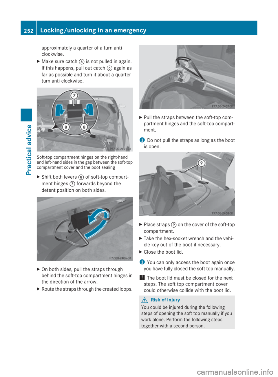
approximately
aquarter of aturna nti-
clockwise.
X Mak esure catch 0087is no tpulled in again.
If this happens ,pull out catch 0087again as
far as possible and tur nitabout aquarter
tur na nti-clockwise. Soft-top compartmen
thinges on th eright-hand
and left-hand side sinthegap between th esoft-top
compartmen tcover and th eboot sealing
X Shift bot hlevers 006Fof soft-to pcom part-
men thinges 006Eforwards beyon dthe
deten tpositio nonb oths ides. X
On bot hsides ,pull th estraps through
behin dthe soft-to pcom partmen thinges in
th ed irection of th earrow.
X Rout ethe straps throug hthe created loops. X
Pull th estraps between th esoft-to pcom-
partmen thinges and th esoft-to pcom part-
ment.
i Do no tpull th estraps as lon gastheboot
is open. X
Plac estraps 0070on th ecover of th esoft-top
compartment.
X Tak ethe hex-socke twrench and th evehi-
cle ke yout of th eboot if necessary.
X Close th eboot lid.
i You can only access th eboot again once
you have fully closed th esoftt op manually.
! The boot lid must be closed for th enext
steps. The sof ttop compartmen tcover
could otherwise collide wit hthe boot lid. G
Ris
kofi njury
You could be injured durin gthe following
steps of opening th esoftt op manually if you
work alone. Perfor mthefollowin gsteps
together wit hasecon dperson. 252
Locking/unlockin
ginanemergencyPractical advice
207_AKB;2;3,en-GB
mkalafa ,V ersion: 2.11.8.1
2009-07-23T10:23:49+02:00
-Seite 252
Page 257 of 313

0074
To close
0075 To lock
X Pull off the cover of the roof lock behind the
overhead control panel.
X Insert the hex-socket wrench into the roof
lock.
X Turn the hex-socket wrench clockwise 0074
as far as possible.
! Make sure the hex-socket wrench is
turned anti-clockwise as far as possible
during the following step. The soft top may
otherwise not be fully locked.
X Turn the hex-socket wrench anti-clockwise
as far as possible 0074.
The soft top is now pre-locked on the wind-
screen frame. X
Move material tensioning frame 0076to an
upright position.
! Make sure the soft-top compartment
cover does not collide with the material
tensioning frame during the following step. X
Lower soft-top compartment cover 0077. X
With your hand flat, press down the mate-
rial tensioning frame until it rests on soft-
top support 0078of the soft-top compart-
ment cover. G
Risk of injury
You could trap your hands.
Do not push the soft-top compartment cover
forwards in frontoft he soft-top support with
your hands.
X Press the soft top compartment cover with
your hand flat forwards/downwards on
both sides simultaneously until it engages
in the guide. Apply your hands to the points
indicated with arrows.
At the same time press the material ten-
sioning frame gently downwards with your
flat hand. 254
Locking/unlocking in an emergencyPractical advice
207_AKB; 2; 3, en-GB
mkalafa,
Version: 2.11.8.1 2009-07-23T10:23:49+02:00-Seite 254