2009 INFINITI QX56 battery
[x] Cancel search: batteryPage 3636 of 4171
DIAGNOSIS AND REPAIR WORKFLOWSTR-7
< BASIC INSPECTION >
C
DE
F
G H
I
J
K L
M A
STR
NP
O
YES >> GO TO 8.
NO >> Repair as needed.
8.“S” CONNECTOR CIRCUIT INSPECTION
Check “S” connector circuit. Refer to STR-11, "
Diagnosis Procedure".
Is
“S” connector circuit normal?
YES >> GO TO 9.
NO >> Repair as needed.
9.ENGINE ROTATION STATUS
Check that the engine can be rotated by hand.
Does the engine turn freely by hand?
YES >> Replace starter motor.
NO >> Perform further diagnosis of engine mechanical or powertrain mechanism. Refer to EM or TM
sections. Once resolved, perform battery test agai n. Refer to diagnostic station instruction man-
ual.
Revision: December 20092009 QX56
Page 3637 of 4171
STR-8
< FUNCTION DIAGNOSIS >
STARTING SYSTEM
FUNCTION DIAGNOSIS
STARTING SYSTEM
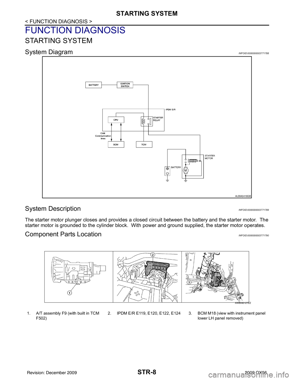
System DiagramINFOID:0000000003771788
System DescriptionINFOID:0000000003771789
The starter motor plunger closes and provides a closed circuit between the battery and the starter motor. The
starter motor is grounded to the cylinder block. With power and ground supplied, the starter motor operates.
Component Parts LocationINFOID:0000000003771790
ALBIA0416GB
1. A/T assembly F9 (with built in TCM
F502) 2. IPDM E/R E119, E120, E122, E124 3. BCM M18 (view with instrument panel
lower LH panel removed)
AWBIA0127ZZ
Revision: December 20092009 QX56
Page 3638 of 4171
STARTING SYSTEMSTR-9
< FUNCTION DIAGNOSIS >
C
DE
F
G H
I
J
K L
M A
STR
NP
O
Component DescriptionINFOID:0000000003771791
Component part
Description
TCM TCM supplies power to the starter relay inside the IPDM E/R when
the selector lever is shifted to the P or N position.
BCM BCM sends a starter request signal to the CPU of the IPDM E/R
over the CAN communication lines.
IPDM E/R CPU inside IPDM E/R operates the starter relay at the request of
the BCM over the CAN communication lines.
Starter motor The starter motor plunger closes and the motor is supplied with
battery power, which in turn cranks the engine, when the “S” ter-
minal is supplied with electric power.
Revision: December 20092009 QX56
Page 3639 of 4171
STR-10
< COMPONENT DIAGNOSIS >
B TERMINAL CIRCUIT
COMPONENT DIAGNOSIS
B TERMINAL CIRCUIT
DescriptionINFOID:0000000003771792
Terminal "2" (B) is constantly supplied with battery power.
Diagnosis ProcedureINFOID:0000000003771793
CAUTION:
Perform diagnosis under the condition that the engine cannot start by the following procedure.
1. Remove fuel pump fuse.
2. Crank or start the engine (where possible) until the fuel pressure is depleted.
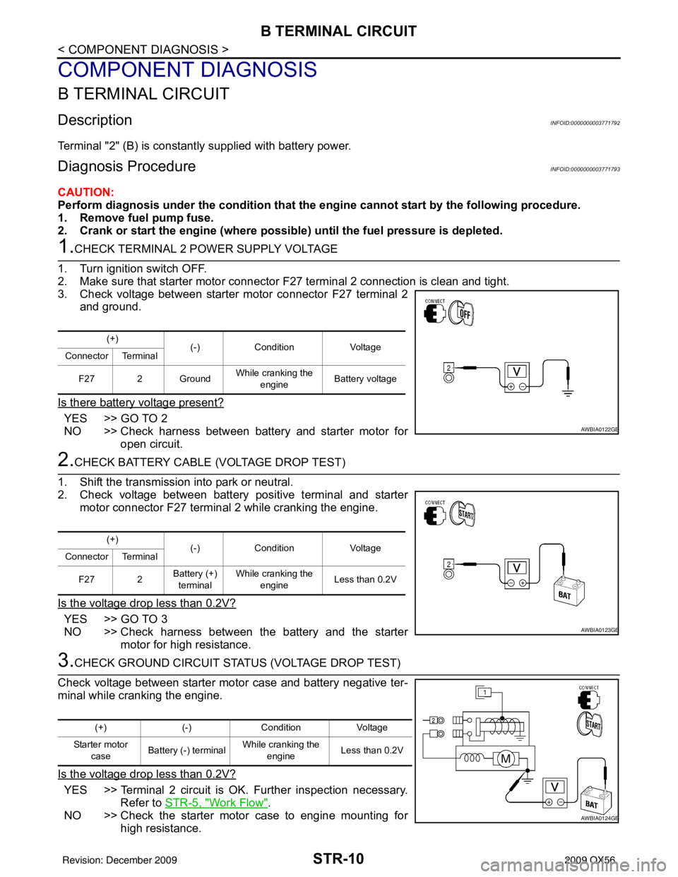
1.CHECK TERMINAL 2 POWER SUPPLY VOLTAGE
1. Turn ignition switch OFF.
2. Make sure that starter motor connector F27 terminal 2 connection is clean and tight.
3. Check voltage between starter motor connector F27 terminal 2
and ground.
Is there battery voltage present?
YES >> GO TO 2
NO >> Check harness between battery and starter motor for open circuit.
2.CHECK BATTERY CABLE (VOLTAGE DROP TEST)
1. Shift the transmission into park or neutral.
2. Check voltage between battery positive terminal and starter motor connector F27 terminal 2 while cranking the engine.
Is the voltage drop less than 0.2V?
YES >> GO TO 3
NO >> Check harness between the battery and the starter motor for high resistance.
3.CHECK GROUND CIRCUIT STATUS (VOLTAGE DROP TEST)
Check voltage between starter motor case and battery negative ter-
minal while cranking the engine.
Is the voltage drop less than 0.2V?
YES >> Terminal 2 circuit is OK. Further inspection necessary. Refer to STR-5, "
Work Flow".
NO >> Check the starter motor case to engine mounting for high resistance.
(+) (-)Condition Voltage
Connector Terminal
F27 2 Ground While cranking the
engine Battery voltage
AWBIA0122GB
(+)
(-)Condition Voltage
Connector Terminal
F27 2 Battery (+)
terminal While cranking the
engine Less than 0.2V
AWBIA0123GB
(+)
(-)Condition Voltage
Starter motor case Battery (-) terminal
While cranking the
engine Less than 0.2V
AWBIA0124GB
Revision: December 20092009 QX56
Page 3640 of 4171
S CONNECTOR CIRCUITSTR-11
< COMPONENT DIAGNOSIS >
C
DE
F
G H
I
J
K L
M A
STR
NP
O
S CONNECTOR CIRCUIT
DescriptionINFOID:0000000003771794
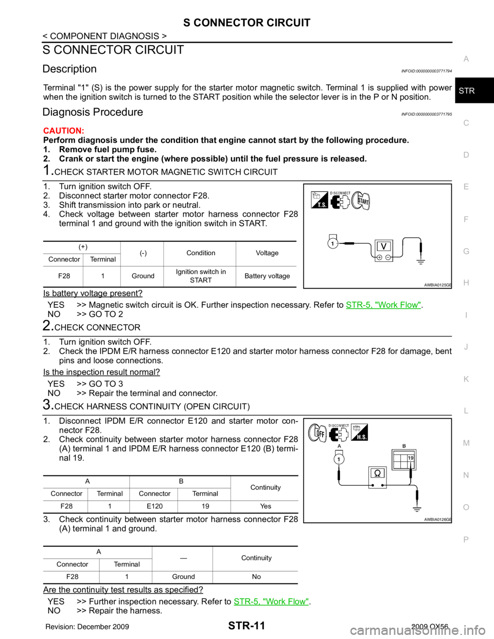
Terminal "1" (S) is the power supply for the starter mo
tor magnetic switch. Terminal 1 is supplied with power
when the ignition switch is turned to the START position while the selector lever is in the P or N position.
Diagnosis ProcedureINFOID:0000000003771795
CAUTION:
Perform diagnosis under the cond ition that engine cannot start by the following procedure.
1. Remove fuel pump fuse.
2. Crank or start the engine (where possi ble) until the fuel pressure is released.
1.CHECK STARTER MOTOR MAGNETIC SWITCH CIRCUIT
1. Turn ignition switch OFF.
2. Disconnect starter motor connector F28.
3. Shift transmission into park or neutral.
4. Check voltage between starter motor harness connector F28 terminal 1 and ground with the ignition switch in START.
Is battery voltage present?
YES >> Magnetic switch circuit is OK. Further inspection necessary. Refer to STR-5, "Work Flow".
NO >> GO TO 2
2.CHECK CONNECTOR
1. Turn ignition switch OFF.
2. Check the IPDM E/R harness connector E120 and starter motor harness connector F28 for damage, bent pins and loose connections.
Is the inspection result normal?
YES >> GO TO 3
NO >> Repair the terminal and connector.
3.CHECK HARNESS CONTI NUITY (OPEN CIRCUIT)
1. Disconnect IPDM E/R connector E120 and starter motor con- nector F28.
2. Check continuity between starter motor harness connector F28 (A) terminal 1 and IPDM E/R harness connector E120 (B) termi-
nal 19.
3. Check continuity between starter motor harness connector F28 (A) terminal 1 and ground.
Are the continuity test results as specified?
YES >> Further inspection necessary. Refer to STR-5, "Work Flow".
NO >> Repair the harness.
(+) (-)Condition Voltage
Connector Terminal
F28 1 Ground Ignition switch in
START Battery voltage
AWBIA0125GB
AB
Continuity
Connector Terminal Connector Terminal
F28 1E120 19 Yes
A —Con tin uit y
Connector Terminal
F28 1Ground No
AWBIA0126GB
Revision: December 20092009 QX56
Page 3652 of 4171

TM-4
Precaution for Supplemental Restraint System
(SRS) "AIR BAG" and "SEAT BELT PRE-TEN-
SIONER" ................................................................
174
Precaution Necessary for Steering Wheel Rota-
tion After Battery Disconnect .................................
174
Precaution for On Board Diagnosis (OBD) System
of A/T and Engine ..................................................
175
Precaution .............................................................175
Service Notice or Precaution .................................176
PREPARATION ..........................................177
PREPARATION .............................................. .177
Special Service Tool ............................................ ..177
Commercial Service Tool ......................................178
ON-VEHICLE MAINTENANCE ..................179
A/T FLUID ....................................................... .179
Checking the A/T Fluid (ATF) .............................. ..179
Changing the A/T Fluid (ATF) ................................181
A/T FLUID COOLER ........................................183
A/T Fluid Cooler Cleaning ................................... ..183
Inspection ..............................................................185
STALL TEST ....................................................186
Inspection and Judgment .................................... ..186
LINE PRESSURE TEST ..................................188
Inspection and Judgment .................................... ..188
ROAD TEST .....................................................190
Description ........................................................... ..190
Check Before Engine Is Started ............................190
Check At Idle .........................................................190
Cruise Test - Part 1 ...............................................191
Cruise Test - Part 2 ...............................................193
Cruise Test - Part 3 ...............................................194
Vehicle Speed When Shifting Gears .....................194
Vehicle Speed When Performing and Releasing
Complete Lock-up .................................................
194
A/T POSITION .................................................195
Adjustment of A/T Position .................................. ..195
Checking of A/T Position .......................................195
ON-VEHICLE REPAIR ............................. ..196
SHIFT CONTROL SYSTEM ........................... .196
A/T Shift Selector Removal and Installation ........ ..196
AIR BREATHER HOSE ...................................197
2WD ........................................................................ ..197
2WD : Removal and Installation ............................197
4WD ........................................................................ ..197
4WD : Removal and Installation ............................197
OIL PAN ...........................................................201
Oil Pan ................................................................. .201
CONTROL VALVE WITH TCM ........................203
Control Valve with TCM and A/T Fluid Tempera-
ture Sensor 2 ....................................................... .
203
REAR OIL SEAL ..............................................212
Rear Oil Seal ........................................................ .212
FLUID COOLER SYSTEM ...............................213
Exploded View ..................................................... .213
Removal and Installation .......................................213
REMOVAL AND INSTALLATION .............214
TRANSMISSION ASSEMBLY ........................ ..214
Removal and Installation (2WD) .......................... .214
Removal and Installation (4WD) ...........................216
DISASSEMBLY AND ASSEMBLY ...........220
OVERHAUL .................................................... ..220
Component .......................................................... .220
Oil Channel ...........................................................227
Location of Adjusting Shims, Needle Bearings,
Thrust Washers and Snap Rings ......................... .
229
DISASSEMBLY .............................................. ..232
Disassembly ......................................................... .232
REPAIR FOR COMPONENT PARTS ..............249
Oil Pump .............................................................. .249
Front Sun Gear, 3rd One-Way Clutch ...................251
Front Carrier, Input Clutch, Rear Internal Gear .....253
Mid Sun Gear, Rear Sun Gear, High and Low Re-
verse Clutch Hub ..................................................
258
High and Low Reverse Clutch ..............................263
Direct Clutch .........................................................265
ASSEMBLY .................................................... ..268
Assembly (1) ........................................................ .268
Adjustment ............................................................281
Assembly (2) .........................................................283
SERVICE DATA AND SPECIFICATIONS
(SDS) ............... ..........................................
290
SERVICE DATA AND SPECIFICATIONS
(SDS) .............................................................. ..
290
General Specification ........................................... .290
Vehicle Speed at Which Gear Shifting Occurs .....290
Vehicle Speed at Which Lock-up Occurs/Releas-
es ..........................................................................
291
Stall Speed ............................................................291
Line Pressure ........................................................291
Input Speed Sensor ..............................................291
Output Speed Sensor ...........................................291
Reverse Brake ......................................................291
Total End Play .......................................................292
Torque Converter .................................................
Revision: December 20092009 QX56
Page 3679 of 4171
ON BOARD DIAGNOSTIC (OBD) SYSTEMTM-31
< FUNCTION DIAGNOSIS >
CEF
G H
I
J
K L
M A
B
TM
N
O P
longer stored. Remember, only one set of freeze frame data can be stored in the ECM. The ECM has the fol-
lowing priorities to update the data.
Both 1st trip freeze frame data and freeze frame data (along with the DTC) are cleared when the ECM mem-
ory is erased.
HOW TO ERASE DTC
The diagnostic trouble code can be erased by CONSULT- III, GST or ECM DIAGNOSTIC TEST MODE as
described following.
If the battery cable is disconnected, the diagnostic trouble code will be lost within 24 hours.
When you erase the DTC, using CONSULT-III or GS T is easier and quicker than switching the mode
selector on the ECM.
The following emission-related diagnostic information is cleared from the ECM memory when erasing DTC
related to OBD-II. For details, refer to EC-42, "Emission-related Diagnostic Information"
.
Diagnostic trouble codes (DTC)
1st trip diagnostic trouble codes (1st trip DTC)
Freeze frame data
1st trip freeze frame data
System readiness test (SRT) codes
Test values
HOW TO ERASE DTC (WITH CONSULT-III)
1. The emission related diagnostic information in the TCM and ECM can be er\
ased by selectioning "ALL
ERASE" in the "Description" of "F INAL CHECK" mode with CONSULT-III.
HOW TO ERASE DTC (WITH GST)
1. If the ignition switch stays “ON” after repair work, be sure to turn ignition switch “OFF” once. Wait at least
10 seconds and then turn it “ON” (engine stopped) again.
2. Select Mode 4 with the Generic Scan Tool (GST). For details refer to EC-72, "Generic Scan Tool (GST)
Function".
HOW TO ERASE DTC (NO TOOLS)
1. Disconnect battery for 24 hours.
2. Reconnect battery.
Malfunction Indicator Lamp (MIL)INFOID:0000000003771823
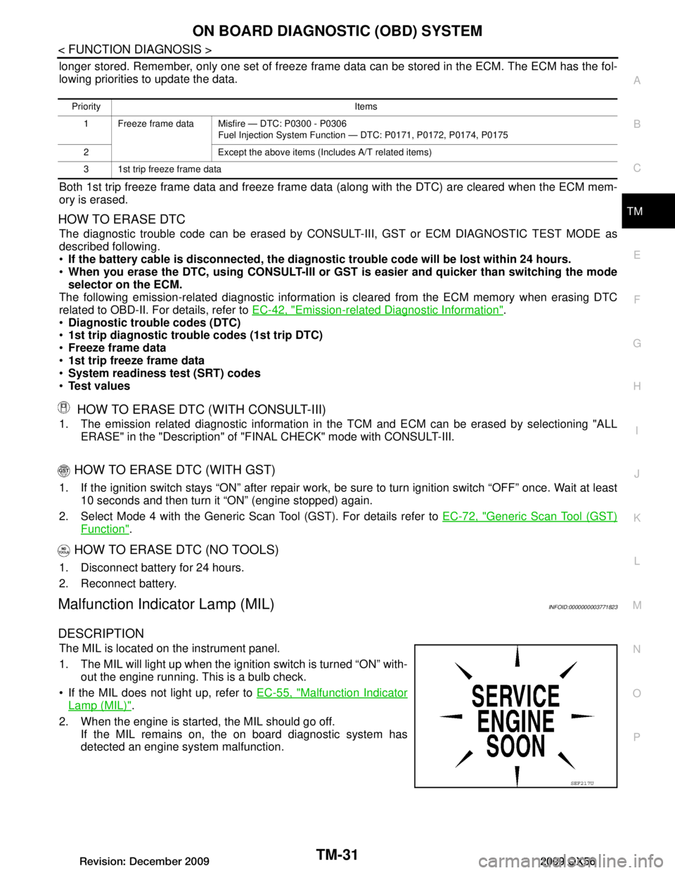
DESCRIPTION
The MIL is located on the instrument panel.
1. The MIL will light up when the ignition switch is turned “ON” with-
out the engine running. This is a bulb check.
If the MIL does not light up, refer to EC-55, "Malfunction Indicator
Lamp (MIL)".
2. When the engine is start ed, the MIL should go off.
If the MIL remains on, the on board diagnostic system has
detected an engine system malfunction.
Priority Items
1 Freeze frame data Misfire — DTC: P0300 - P0306 Fuel Injection System Function — DTC: P0171, P0172, P0174, P0175
2 Except the above items (Includes A/T related items)
3 1st trip freeze frame data
SEF217U
Revision: December 20092009 QX56
Page 3682 of 4171
TM-34
< FUNCTION DIAGNOSIS >
DIAGNOSIS SYSTEM (TCM)
*1: Refer to EC-55, "Malfunction Indicator Lamp (MIL)".
*2:These malfunctions cannot be displayed MIL if another malfunction is assigned to MIL.
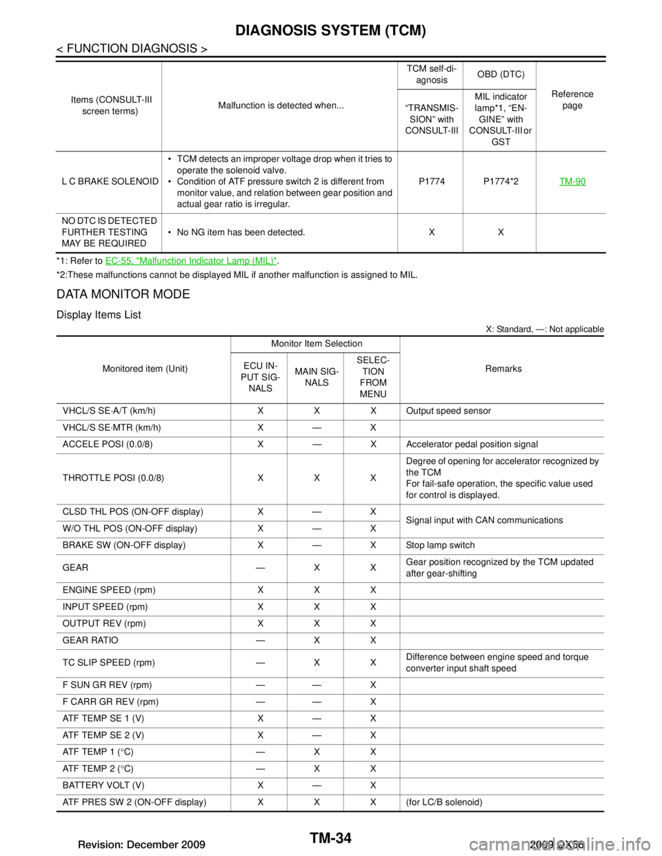
DATA MONITOR MODE
Display Items List
X: Standard, —: Not applicable
L C BRAKE SOLENOID TCM detects an improper voltage drop when it tries to
operate the solenoid valve.
Condition of ATF pressure switch 2 is different from
monitor value, and relation between gear position and
actual gear ratio is irregular. P1774 P1774*2
TM-90
NO DTC IS DETECTED
FURTHER TESTING
MAY BE REQUIRED No NG item has been detected. X X
Items (CONSULT-III
screen terms) Malfunction is detected when... TCM self-di-
agnosis OBD (DTC)
Reference page
“TRANSMIS-
SION” with
CONSULT-III MIL indicator
lamp*1, “EN-
GINE” with
CONSULT-III or
GST
Monitored item (Unit) Monitor Item Selection
Remarks
ECU IN-
PUT SIG-
NALS MAIN SIG-
NALS SELEC-
TION
FROM
MENU
VHCL/S SE·A/T (km/h) X X X Output speed sensor
VHCL/S SE·MTR (km/h) X — X
ACCELE POSI (0.0/8) X — X Accelerator pedal position signal
THROTTLE POSI (0.0/8) X X X Degree of opening for accelerator recognized by
the TCM
For fail-safe operation, the specific value used
for control is displayed.
CLSD THL POS (ON-OFF display) X — X Signal input with CAN communications
W/O THL POS (ON-OFF display) X — X
BRAKE SW (ON-OFF display) X — X Stop lamp switch
GEAR — X X Gear position recognized by the TCM updated
after gear-shifting
ENGINE SPEED (rpm) X X X
INPUT SPEED (rpm) X X X
OUTPUT REV (rpm) X X X
GEAR RATIO — X X
TC SLIP SPEED (rpm) — X X Difference between engine speed and torque
converter input shaft speed
F SUN GR REV (rpm) — — X
F CARR GR REV (rpm) — — X
ATF TEMP SE 1 (V) X — X
ATF TEMP SE 2 (V) X — X
ATF TEMP 1 ( °C) — X X
ATF TEMP 2 ( °C) — X X
BATTERY VOLT (V) X — X
ATF PRES SW 2 (ON-OFF display) X X X (for LC/B solenoid)
Revision: December 20092009 QX56