2009 INFINITI QX56 battery
[x] Cancel search: batteryPage 3421 of 4171
![INFINITI QX56 2009 Factory Service Manual VEHICLE SECURITY SYSTEMSEC-111
< ON-VEHICLE REPAIR > [WITH INTELLIGENT KEY SYSTEM]
C
D
E
F
G H
I
J
L
M A
B
SEC
N
O P
ON-VEHICLE REPAIR
VEHICLE SECURITY SYSTEM
Removal and InstallationINFOID:0000000003 INFINITI QX56 2009 Factory Service Manual VEHICLE SECURITY SYSTEMSEC-111
< ON-VEHICLE REPAIR > [WITH INTELLIGENT KEY SYSTEM]
C
D
E
F
G H
I
J
L
M A
B
SEC
N
O P
ON-VEHICLE REPAIR
VEHICLE SECURITY SYSTEM
Removal and InstallationINFOID:0000000003](/manual-img/42/57031/w960_57031-3420.png)
VEHICLE SECURITY SYSTEMSEC-111
< ON-VEHICLE REPAIR > [WITH INTELLIGENT KEY SYSTEM]
C
D
E
F
G H
I
J
L
M A
B
SEC
N
O P
ON-VEHICLE REPAIR
VEHICLE SECURITY SYSTEM
Removal and InstallationINFOID:0000000003775949
REMOTE KEYLESS ENTRY RECEIVER
Removal
1. Remove the instrument panel. Refer to IP-13, "Removal and Installation".
2. Disconnect the wire harness (1), remove the bolt (A) and the RKE receiver (2).
Installation
Installation is in the reverse order of removal.
INTELLIGENT KEY UNIT
Removal
1. Remove the instrument panel. Refer to IP-13, "Removal and Installation".
2. Disconnect the wire harness (1), remove the bolt (A) and the Intelligent key unit (2).
Installation
Installation is in the reverse order of removal.
NATS ANTENNA AMP
NOTE:
• If NATS antenna amp. is not installed correctly, NV IS (NATS) system will not operate properly and "SELF-
DIAG RESULTS" on CONSULT-III screen will s how "LOCK MODE" or "CHAIN OF IMMU-KEY".
• Initialization is not necessary when only the NATS antenna amp. is replaced with a new one.
Removal
1. Disconnect the battery negative terminal.
2. Remove cluster lid A. Refer to IP-15, "
Removal and Installation".
ALKIA0537ZZ
ALKIA0666ZZ
Revision: December 20092009 QX56
Page 3423 of 4171

SN
SN-1
DRIVER INFORMATION & MULTIMEDIA
C
DE
F
G H
I
J
K L
M B
SECTION SN
A
O P
CONTENTS
SONAR SYSTEM
BASIC INSPECTION ....... .............................3
DIAGNOSIS AND REPAIR WORKFLOW ..... .....3
Work Flow ........................................................... ......3
INSPECTION AND ADJUSTMENT .....................5
Preliminary Check ............................................... ......5
FUNCTION DIAGNOSIS ...............................6
REAR SONAR SYSTEM ................................ .....6
System Diagram .................................................. ......6
System Description ...................................................6
Component Parts Location ........................................7
Component Description .............................................7
Self-Diagnosis Function ............................................7
FRONT AND REAR SONAR SYSTEM .......... ....10
System Diagram .................................................. ....10
System Description .................................................10
Component Parts Location ......................................11
Component Description ...........................................12
CONSULT-III Function (SONAR) ............................12
COMPONENT DIAGNOSIS .........................13
POWER SUPPLY AND GROUND CIRCUIT .. ....13
Diagnosis Procedure (With Rear Sonar System) ....13
Diagnosis Procedure (With Front and Rear Sonar
System) ............................................................... ....
13
SONAR SENSOR CIRCUIT INSPECTION ........15
Description .......................................................... ....15
Diagnosis Procedure (With Rear Sonar System) ....15
Diagnosis Procedure (With Front and Rear Sonar
System) ...................................................................
15
SONAR BUZZER CIRCUIT INSPECTION .........17
Description .......................................................... ....17
Diagnosis Procedure (With Rear Sonar System) ....17
Diagnosis Procedure (With Front and Rear Sonar
System) ...................................................................
17
Component Inspection ......................................... ....18
SONAR SYSTEM OFF SWITCH CIRCUIT IN-
SPECTION ........................................................
19
Description ........................................................... ....19
Diagnosis Procedure (With Rear Sonar System) ....19
Diagnosis Procedure (With Front and Rear Sonar
System) ............................................................... ....
19
Component Inspection .............................................20
ECU DIAGNOSIS .........................................21
SONAR CONTROL UNIT FOR REAR SONAR
SYSTEM ...................... ......................................
21
Reference Value .................................................. ....21
Wiring Diagram ........................................................23
DTC Index ...............................................................30
SONAR CONTROL UNIT FOR FRONT AND
REAR SONAR SYSTEM ...................................
31
Reference Value ......................................................31
Wiring Diagram ........................................................33
DTC Index ...............................................................44
SYMPTOM DIAGNOSIS ..............................45
SONAR SYSTEM SYMPTOMS ........................45
Symptom Table ................................................... ....45
PRECAUTION ..............................................46
PRECAUTION ...................................................46
Precaution for Supplemental Restraint System
(SRS) "AIR BAG" and "SEAT BELT PRE-TEN-
SIONER" ............................................................. ....
46
Precaution Necessary for Steering Wheel Rota-
tion After Battery Disconnect ...................................
46
PREPARATION ...........................................48
PREPARATION .................................................48
Commercial Service Tool .................................... ....48
Revision: December 20092009 QX56
Page 3435 of 4171
SN
POWER SUPPLY AND GROUND CIRCUITSN-13
< COMPONENT DIAGNOSIS >
C
DE
F
G H
I
J
K L
M B A
O P
COMPONENT DIAGNOSIS
POWER SUPPLY AND GROUND CIRCUIT
Diagnosis Procedure (With Rear Sonar System)INFOID:0000000004173800
INSPECTION FOR POWER SUPPLY AND GROUND CIRCUIT
1.CHECK FUSES
Check for blown rear sonar system fuses.
Are any fuses blown?
YES >> If fuse is blown, be sure to eliminate cause of malfunction before installing new fuse. Refer to GI-
41, "Circuit Inspection".
NO >> GO TO 2.
2.CHECK POWER SUPPLY CIRCUIT
1. Disconnect sonar control unit connector.
2. Turn ignition switch ON.
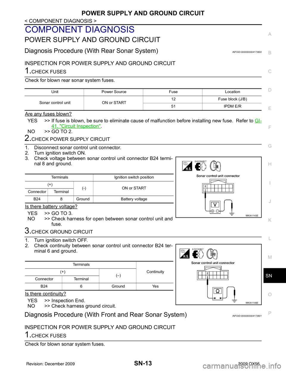
3. Check voltage between sonar control unit connector B24 termi- nal 8 and ground.
Is there battery voltage?
YES >> GO TO 3.
NO >> Check harness for open between sonar control unit and fuse.
3.CHECK GROUND CIRCUIT
1. Turn ignition switch OFF.
2. Check continuity between sonar control unit connector B24 ter- minal 6 and ground.
Is there continuity?
YES >> Inspection End.
NO >> Check harness ground circuit.
Diagnosis Procedure (With Front and Rear Sonar System)INFOID:0000000004173801
INSPECTION FOR POWER SUPPLY AND GROUND CIRCUIT
1.CHECK FUSES
Check for blown sonar system fuses.
Unit Power Source FuseLocation
Sonar control unit ON or START 12
Fuse block (J/B)
51 IPDM E/R
Terminals Ignition switch position
(+) (-) ON or START
Connector Terminal
B24 8 Ground Battery voltage
WKIA1145E
Te r m i n a l s
Continuity
(+)
(–)
Connector Terminal
B24 6 Ground Yes
WKIA1146E
Revision: December 20092009 QX56
Page 3436 of 4171
SN-14
< COMPONENT DIAGNOSIS >
POWER SUPPLY AND GROUND CIRCUIT
Are any fuses blown?
YES >> If fuse is blown, be sure to eliminate cause of malfunction before installing new fuse. Refer to GI-
41, "Circuit Inspection".
NO >> GO TO 2.
2.CHECK POWER SUPPLY CIRCUIT
1. Disconnect sonar control unit connector B56.
2. Turn ignition switch ON.
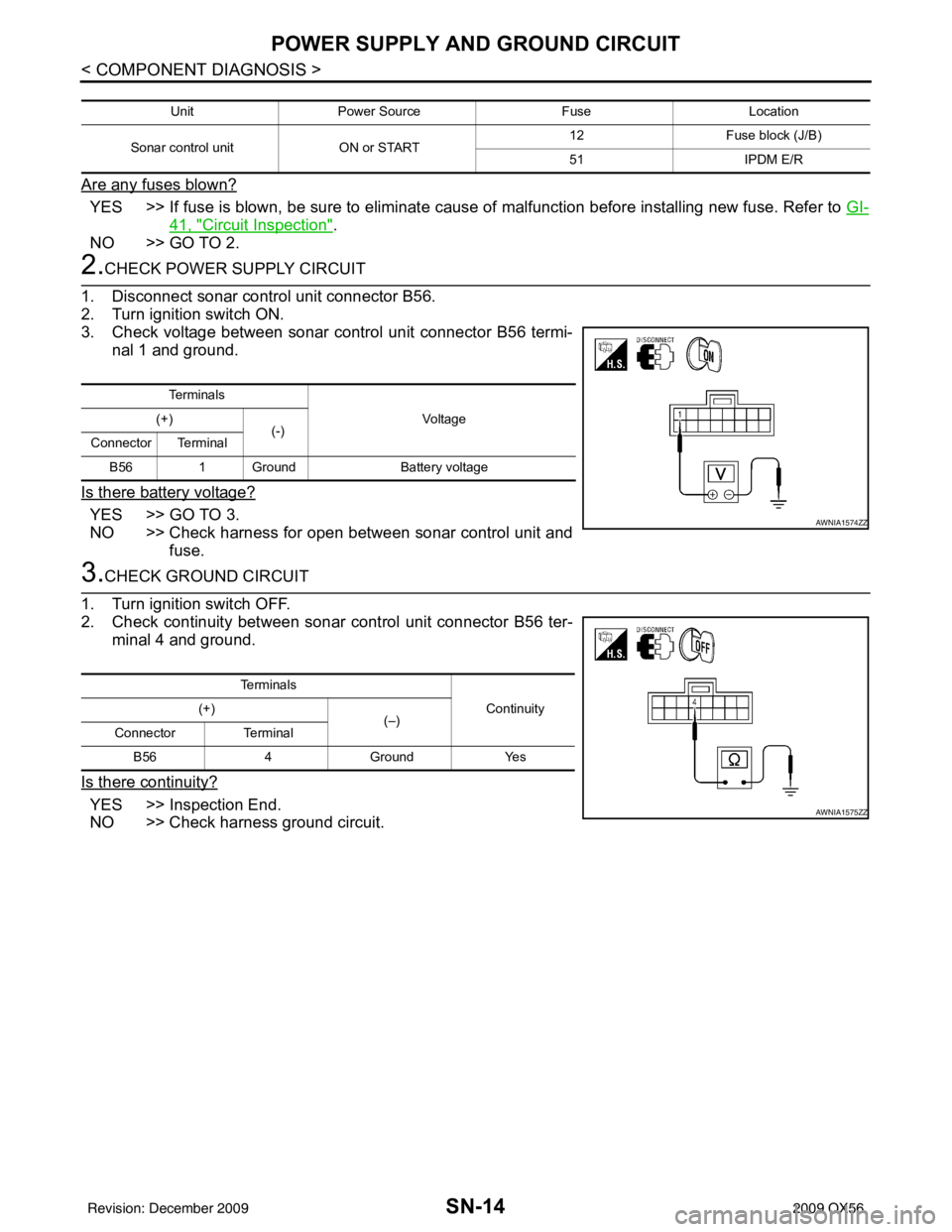
3. Check voltage between sonar control unit connector B56 termi- nal 1 and ground.
Is there battery voltage?
YES >> GO TO 3.
NO >> Check harness for open between sonar control unit and fuse.
3.CHECK GROUND CIRCUIT
1. Turn ignition switch OFF.
2. Check continuity between sonar control unit connector B56 ter-
minal 4 and ground.
Is there continuity?
YES >> Inspection End.
NO >> Check harness ground circuit.
Unit Power Source FuseLocation
Sonar control unit ON or START 12
Fuse block (J/B)
51 IPDM E/R
Te r m i n a l s
Vo l ta g e
(+)
(-)
Connector Terminal
B56 1 Ground Battery voltage
AWNIA1574ZZ
Te r m i n a l s
Continuity
(+)
(–)
Connector Terminal
B56 4Ground Yes
AWNIA1575ZZ
Revision: December 20092009 QX56
Page 3442 of 4171
SN-20
< COMPONENT DIAGNOSIS >
SONAR SYSTEM OFF SWITCH CIRCUIT INSPECTION
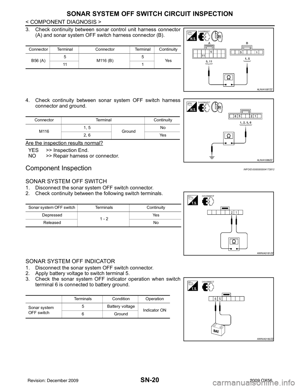
3. Check continuity between sonar control unit harness connector(A) and sonar system OFF switch harness connector (B).
4. Check continuity between sonar system OFF switch harness connector and ground.
Are the inspection results normal?
YES >> Inspection End.
NO >> Repair harness or connector.
Component InspectionINFOID:0000000004173812
SONAR SYSTEM OFF SWITCH
1. Disconnect the sonar system OFF switch connector.
2. Check continuity between the following switch terminals.
SONAR SYSTEM OFF INDICATOR
1. Disconnect the sonar system OFF switch connector.
2. Apply battery voltage to switch terminal 5.
3. Check the sonar system OFF indicator operation when switch terminal 6 is connected to battery ground.
Connector Terminal Connector Terminal Continuity
B56 (A) 5
M116 (B) 5
Ye s
11 1
ALNIA1087ZZ
ConnectorTerminalContinuity
M116 1, 5
Ground No
2, 6 Yes
ALNIA1088ZZ
Sonar system OFF switch Terminals Continuity
Depressed 1 - 2Ye s
Released No
AWNIA0181ZZ
Terminals Condition Operation
Sonar system
OFF switch 5
Battery voltage
Indicator ON
6G ro u nd
AWNIA0182ZZ
Revision: December 20092009 QX56
Page 3443 of 4171
SN
SONAR CONTROL UNIT FOR REAR SONAR SYSTEMSN-21
< ECU DIAGNOSIS >
C
DE
F
G H
I
J
K L
M B A
O P
ECU DIAGNOSIS
SONAR CONTROL UNIT FO R REAR SONAR SYSTEM
Reference ValueINFOID:0000000003776753
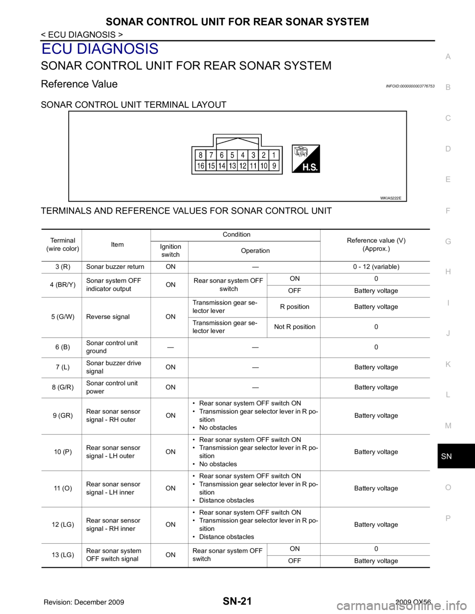
SONAR CONTROL UNIT TERMINAL LAYOUT
TERMINALS AND REFERENCE VA LUES FOR SONAR CONTROL UNIT
WKIA5222E
Te r m i n a l
(wire color) Item Condition
Reference value (V)
(Approx.)
Ignition
switch Operation
3 (R) Sonar buzzer return ON —0 - 12 (variable)
4 (BR/Y) Sonar system OFF
indicator output ON
Rear sonar system OFF
switch ON
0
OFF Battery voltage
5 (G/W) Reverse signal ONTransmission gear se-
lector lever
R position
Battery voltage
Transmission gear se-
lector lever Not R position
0
6 (B) Sonar control unit
ground ——
0
7 (L) Sonar buzzer drive
signal
ON
— Battery voltage
8 (G/R) Sonar control unit
power ON
— Battery voltage
9 (GR) Rear sonar sensor
signal - RH outer
ON• Rear sonar system OFF switch ON
• Transmission gear selector lever in R po-
sition
• No obstacles Battery voltage
10 (P) Rear sonar sensor
signal - LH outer
ON• Rear sonar system OFF switch ON
• Transmission gear selector lever in R po-
sition
• No obstacles Battery voltage
11 ( O ) Rear sonar sensor
signal - LH inner
ON• Rear sonar system OFF switch ON
• Transmission gear selector lever in R po-
sition
• Distance obstacles Battery voltage
12 (LG) Rear sonar sensor
signal - RH inner
ON• Rear sonar system OFF switch ON
• Transmission gear selector lever in R po-
sition
• Distance obstacles Battery voltage
13 (LG) Rear sonar system
OFF switch signal
ONRear sonar system OFF
switch ON
0
OFF Battery voltage
Revision: December 20092009 QX56
Page 3444 of 4171

SN-22
< ECU DIAGNOSIS >
SONAR CONTROL UNIT FOR REAR SONAR SYSTEM
15 (Y)Rear sonar sensor
ground
ON
— 0
16 (LG/B) Rear sonar sensor
power ON Ignition switch ON
Battery voltage
Te r m i n a l
(wire color) Item Condition
Reference value (V)
(Approx.)
Ignition
switch Operation
Revision: December 20092009 QX56
Page 3453 of 4171
SN
SONAR CONTROL UNIT FOR FRONT AND REAR SONAR SYSTEMSN-31
< ECU DIAGNOSIS >
C
DE
F
G H
I
J
K L
M B A
O P
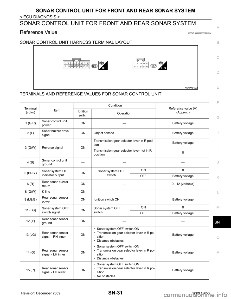
SONAR CONTROL UNIT FOR FR ONT AND REAR SONAR SYSTEM
Reference ValueINFOID:0000000003776756
SONAR CONTROL UNIT HARNESS TERMINAL LAYOUT
TERMINALS AND REFERENCE VA LUES FOR SONAR CONTROL UNIT
AWNIA1547ZZ
Te r m i n a l
(color) Item Condition
Reference value (V)
(Approx.)
Ignition
switch Operation
1 (G/R) Sonar control unit
power ON
— Battery voltage
2 (L) Sonar buzzer drive
signal
ON Object sensed
Battery voltage
3 (G/W) Reverse signal ONTransmission gear selector lever in R posi-
tion
Battery voltage
Transmission gear selector lever not in R
position 0
4 (B) Sonar control unit
ground ——
—
5 (BR/Y) Sonar system OFF
indicator output ON
Sonar system OFF
switch ON
0
OFF Battery voltage
6 (R) Rear sonar buzzer
return
ON
— 0 - 12 (variable)
8 (G/W) K-line ON— —
9 (LG/B) Rear sonar sensor
power ON Ignition switch ON
Battery voltage
11 ( L G ) Sonar system OFF
switch signal
ONSonar system OFF
switch ON
0
OFF Battery voltage
12 (Y) Rear sonar sensor
ground ON
— —
13 (LG) Rear sonar sensor
signal - RH inner ON• Sonar system OFF switch ON
• Transmission gear selector lever in R po-
sition
• Distance obstacles Battery voltage
14 (O) Rear sonar sensor
signal - LH inner ON• Sonar system OFF switch ON
• Transmission gear selector lever in R po-
sition
• Distance obstacles Battery voltage
15 (P) Rear sonar sensor
signal - LH outer ON• Sonar system OFF switch ON
• Transmission gear selector lever in R po-
sition
• No obstacles Battery voltage
Revision: December 20092009 QX56