2009 INFINITI QX56 tire pressure
[x] Cancel search: tire pressurePage 3163 of 4171

SHOCK ABSORBERRSU-15
< REMOVAL AND INSTALLATION >
C
DF
G H
I
J
K L
M A
B
RSU
N
O P
SHOCK ABSORBER
Removal and InstallationINFOID:0000000005889873
REMOVAL
1. Remove the wheel and tire assembly using power tool. Refer to WT-41, "Adjustment".
2. If equipped with the rear load leveling air suspens ion system, use CONSULT-III "EXHAUST SOLENOID"
active test to release the air pressure from the rear load leveling air suspension system.
3. Disconnect the height sensor electrical connector.
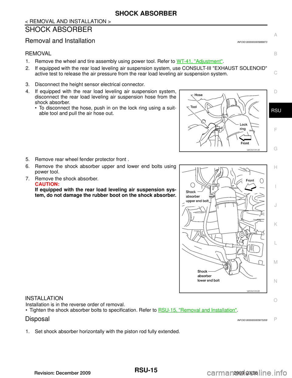
4. If equipped with the rear load leveling air suspension system, disconnect the rear load leveling air suspension hose from the
shock absorber.
To disconnect the hose, push in on the lock ring using a suit-able tool and pull the air hose out.
5. Remove rear wheel fender protector front .
6. Remove the shock absorber upper and lower end bolts using power tool.
7. Remove the shock absorber. CAUTION:
If equipped with the rear lo ad leveling air suspension sys-
tem, do not damage the rubber boot on the shock absorber.
INSTALLATION
Installation is in the reverse order of removal.
Tighten the shock absorber bolts to specification. Refer to RSU-15, "Removal and Installation"
.
DisposalINFOID:0000000005873208
1. Set shock absorber horizontally with the piston rod fully extended.
LEIA0081E
LEIA0082E
Revision: December 20092009 QX56
Page 3165 of 4171

SUSPENSION ARMRSU-17
< REMOVAL AND INSTALLATION >
C
DF
G H
I
J
K L
M A
B
RSU
N
O P
SUSPENSION ARM
Removal and InstallationINFOID:0000000005889874
REMOVAL
1. If equipped with rear load leveling air suspension system, use CONSULT-III “EXHAUST SOLENOID”
active test to release the air pressure from the rear load leveling air suspension system.
2. If equipped with the rear load leveling air suspension system, disconnect the electrical connectors for the
height sensor and the rear load leveling air suspension compressor assembly.
3. If equipped with the rear load leveling air suspension system, unclip the rubber cover to access the rear
load leveling air suspension compressor assembly.
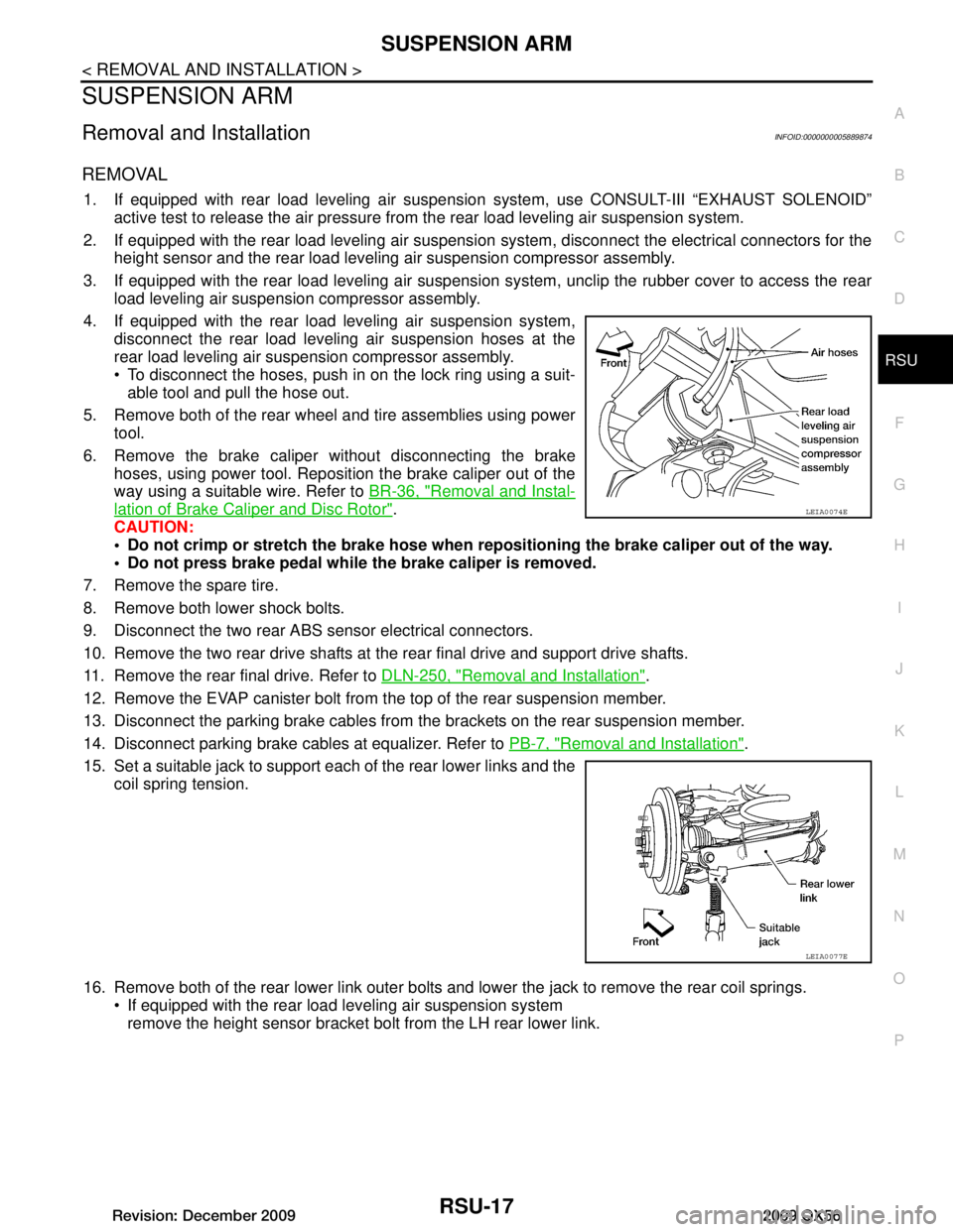
4. If equipped with the rear load leveling air suspension system, disconnect the rear load leveling air suspension hoses at the
rear load leveling air suspension compressor assembly.
To disconnect the hoses, push in on the lock ring using a suit-able tool and pull the hose out.
5. Remove both of the rear wheel and tire assemblies using power tool.
6. Remove the brake caliper without disconnecting the brake hoses, using power tool. Reposition the brake caliper out of the
way using a suitable wire. Refer to BR-36, "Removal and Instal-
lation of Brake Caliper and Disc Rotor".
CAUTION:
Do not crimp or stretch the brake hose when re positioning the brake caliper out of the way.
Do not press brake pedal while the brake caliper is removed.
7. Remove the spare tire.
8. Remove both lower shock bolts.
9. Disconnect the two rear ABS sensor electrical connectors.
10. Remove the two rear drive shafts at t he rear final drive and support drive shafts.
11. Remove the rear final drive. Refer to DLN-250, "Removal and Installation"
.
12. Remove the EVAP canister bolt from the top of the rear suspension member.
13. Disconnect the parking brake cables from t he brackets on the rear suspension member.
14. Disconnect parking brake cables at equalizer. Refer to PB-7, "Removal and Installation"
.
15. Set a suitable jack to support each of the rear lower links and the coil spring tension.
16. Remove both of the rear lower link outer bolts and lower the jack to remove the rear coil springs. If equipped with the rear load leveling air suspension systemremove the height sensor bracket bolt from the LH rear lower link.
LEIA0074E
LEIA0077E
Revision: December 20092009 QX56
Page 3167 of 4171

FRONT LOWER LINKRSU-19
< REMOVAL AND INSTALLATION >
C
DF
G H
I
J
K L
M A
B
RSU
N
O P
FRONT LOWER LINK
Removal and InstallationINFOID:0000000005889875
REMOVAL
1. Remove the wheel and tire assembly using power tool.
2. If equipped with rear load leveling air suspension system, use CONSULT-III “EXHAUST SOLENOID”
active test to release the air pressure from the rear load leveling air suspension system.
3. Set suitable jack to support rear lower link.
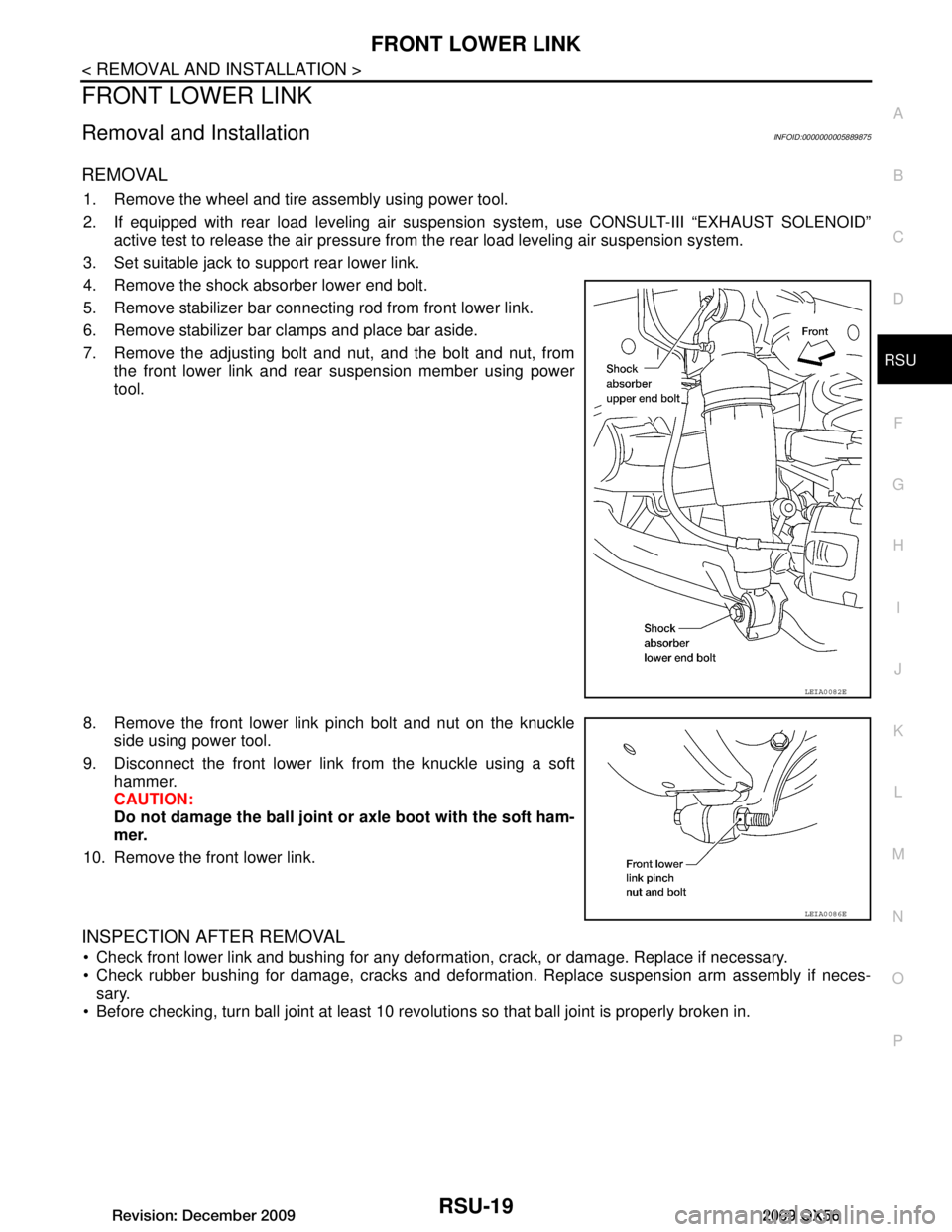
4. Remove the shock absorber lower end bolt.
5. Remove stabilizer bar connecting rod from front lower link.
6. Remove stabilizer bar clamps and place bar aside.
7. Remove the adjusting bolt and nut, and the bolt and nut, from the front lower link and rear suspension member using power
tool.
8. Remove the front lower link pinch bolt and nut on the knuckle side using power tool.
9. Disconnect the front lower link from the knuckle using a soft hammer.
CAUTION:
Do not damage the ball joint or axle boot with the soft ham-
mer.
10. Remove the front lower link.
INSPECTION AFTER REMOVAL
Check front lower link and bushing for any deformation, crack, or damage. Replace if necessary.
Check rubber bushing for damage, cracks and deformation. Replace suspension arm assembly if neces-
sary.
Before checking, turn ball joint at least 10 revo lutions so that ball joint is properly broken in.
LEIA0082E
LEIA0086E
Revision: December 20092009 QX56
Page 3169 of 4171

REAR LOWER LINK & COIL SPRINGRSU-21
< REMOVAL AND INSTALLATION >
C
DF
G H
I
J
K L
M A
B
RSU
N
O P
REAR LOWER LINK & COIL SPRING
Removal and InstallationINFOID:0000000005889876
REMOVAL
1. Remove the wheel and tire assembly using power tool. Refer to WT-41, "Adjustment".
2. If equipped with rear load leveling air suspension system, use CONSULT-III “EXHAUST SOLENOID”
active test to release the air pressure from the rear load leveling air suspension system.
3. If equipped with the rear load leveling air suspension system, for removing the LH rear lower link and coil spring, remove the
height sensor arm bracket bolt from the rear lower link.
4. Remove speed sensor harness and brackets from rear lower link.
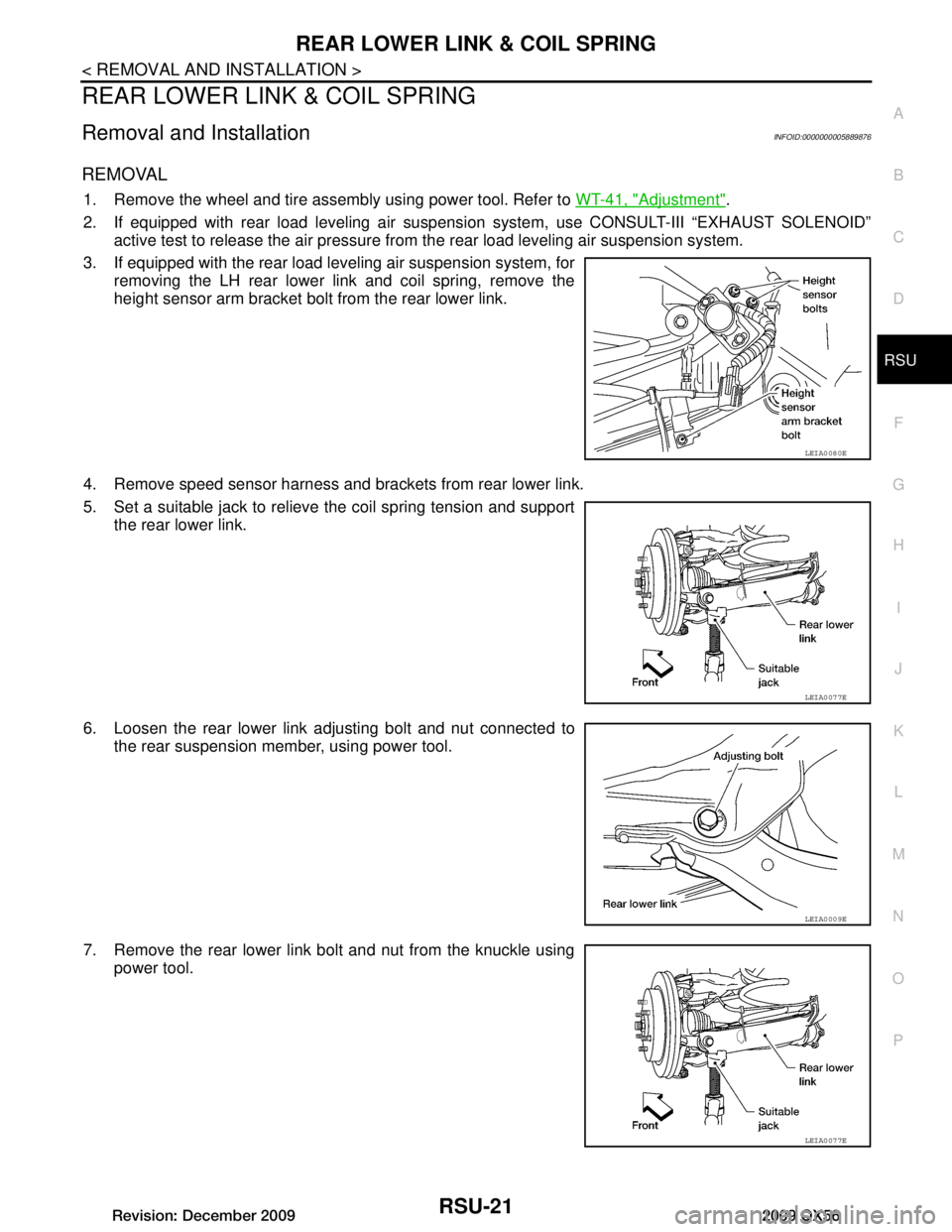
5. Set a suitable jack to relieve the coil spring tension and support the rear lower link.
6. Loosen the rear lower link adjusting bolt and nut connected to the rear suspension member, using power tool.
7. Remove the rear lower link bolt and nut from the knuckle using power tool.
LEIA0080E
LEIA0077E
LEIA0009E
LEIA0077E
Revision: December 20092009 QX56
Page 3328 of 4171
![INFINITI QX56 2009 Factory Service Manual SEC-18
< FUNCTION DIAGNOSIS >[WITH INTELLIGENT KEY SYSTEM]
DIAGNOSIS SYSTEM (BCM)
DIAGNOSIS SYSTEM (BCM)
COMMON ITEM
COMMON ITEM : CONSULT-III Fu
nction (BCM - COMMON ITEM)INFOID:0000000004221462
APPL INFINITI QX56 2009 Factory Service Manual SEC-18
< FUNCTION DIAGNOSIS >[WITH INTELLIGENT KEY SYSTEM]
DIAGNOSIS SYSTEM (BCM)
DIAGNOSIS SYSTEM (BCM)
COMMON ITEM
COMMON ITEM : CONSULT-III Fu
nction (BCM - COMMON ITEM)INFOID:0000000004221462
APPL](/manual-img/42/57031/w960_57031-3327.png)
SEC-18
< FUNCTION DIAGNOSIS >[WITH INTELLIGENT KEY SYSTEM]
DIAGNOSIS SYSTEM (BCM)
DIAGNOSIS SYSTEM (BCM)
COMMON ITEM
COMMON ITEM : CONSULT-III Fu
nction (BCM - COMMON ITEM)INFOID:0000000004221462
APPLICATION ITEM
CONSULT-III performs the following functions via CAN communication with BCM.
SYSTEM APPLICATION
BCM can perform the following functions for each system.
NOTE:
It can perform the diagnosis modes except the following for all sub system selection items.
IMMU
IMMU : CONSULT-III Function (BCM - IMMU)INFOID:0000000004221463
DATA MONITOR
Diagnosis mode Function Description
WORK SUPPORT Changes the setting for each system function.
SELF-DIAG RESULTS Displays the diagnosis results judged by BCM. Refer to BCS-51, "
DTCIndex".
CAN DIAG SUPPORT MNTR Monitors the reception status of CAN communication viewed from BCM.
DATA MONITOR The BCM input/output signals are displayed.
ACTIVE TEST The signals used to activate each device are forcibly supplied from BCM.
ECU IDENTIFICATION The BCM part number is displayed.
CONFIGURATION • Enables to read and save the vehicle specification.
• Enables to write the vehicle specification when replacing BCM.
System
Sub system selection item Diagnosis mode
WORK SUPPORT DATA MONITOR ACTIVE TEST
BCM BCM ×
Door lock DOOR LOCK ×××
Rear window defogger REAR DEFOGGER ×
Warning chime BUZZER ××
Interior room lamp timer INT LAMP ×××
Remote keyless entry system MULTI REMOTE ENT ××
Exterior lamp HEAD LAMP ×××
Wiper and washer WIPER ×××
Turn signal and hazard warning lamps FLASHER ××
Air conditioner AIR CONDITONER ×
Intelligent Key system INTELLIGENT KEY ×
Combination switch COMB SW ×
Immobilizer IMMU ××
Interior room lamp battery saver BATTERY SAVER ×××
Back door open TRUNK ××
RAP (retained accessory power) RETAINED PWR ×××
Signal buffer system SIGNAL BUFFER ××
TPMS (tire pressure monitoring sys-
tem) AIR PRESSURE MONITOR
×××
Vehicle security system PANIC ALARM ×
Revision: December 20092009 QX56
Page 3362 of 4171
![INFINITI QX56 2009 Factory Service Manual SEC-52
< ECU DIAGNOSIS >[WITH INTELLIGENT KEY SYSTEM]
BCM (BODY CONTROL MODULE)
Te r m i n a lWire
color Signal name Signal
input/
output Measuring condition
Reference value or waveform
(Approx.)
Ig INFINITI QX56 2009 Factory Service Manual SEC-52
< ECU DIAGNOSIS >[WITH INTELLIGENT KEY SYSTEM]
BCM (BODY CONTROL MODULE)
Te r m i n a lWire
color Signal name Signal
input/
output Measuring condition
Reference value or waveform
(Approx.)
Ig](/manual-img/42/57031/w960_57031-3361.png)
SEC-52
< ECU DIAGNOSIS >[WITH INTELLIGENT KEY SYSTEM]
BCM (BODY CONTROL MODULE)
Te r m i n a lWire
color Signal name Signal
input/
output Measuring condition
Reference value or waveform
(Approx.)
Ignition
switch Operation or condition
1BR/W Ignition keyhole illumi-
nation Output OFFDoor is locked (SW OFF)
Battery voltage
Door is unlocked (SW ON) 0V
2SB Combination switch
input 5 Input ON
Lighting, turn, wiper OFF
Wiper dial position 4
3G/Y Combination switch
input 4 Input ONLighting, turn, wiper OFF
Wiper dial position 4
4Y Combination switch
input 3 Input ON
Lighting, turn, wiper OFF
Wiper dial position 4
5G/B Combination switch
input 2
Input ONLighting, turn, wiper OFF
Wiper dial position 4
6V Combination switch
input 1
9GR/R Rear window defogger
switch
Input ONRear window defogger switch
ON
0V
Rear window defogger switch
OFF 5V
10 G Hazard lamp flash Input OFF ON (opening or closing)
0V
OFF (other than above) Battery voltage
11 O Ignition switch (ACC
or ON)
InputACC or
ON Ignition switch ACC or ON
Battery voltage
12 R/L Front door switch RH Input OFF ON (open)
0V
OFF (closed) Battery voltage
13 GR Rear door switch RH Input OFF ON (open)
0V
OFF (closed) Battery voltage
15 L/W Tire pressure warning
check connector
Input OFF
—5V
18 P Remote keyless entry
receiver and optical
sensor (ground)
Output OFF
—0V
SKIA5291E
SKIA5292E
SKIA5291E
SKIA5292E
Revision: December 20092009 QX56
Page 3388 of 4171
![INFINITI QX56 2009 Factory Service Manual SEC-78
< ECU DIAGNOSIS >[WITH INTELLIGENT KEY SYSTEM]
BCM (BODY CONTROL MODULE)
CONSULT display
Fail-safeIntelligent Key
warning lamp ON Tire pressure
monitor warning lamp ON Reference page
No DTC INFINITI QX56 2009 Factory Service Manual SEC-78
< ECU DIAGNOSIS >[WITH INTELLIGENT KEY SYSTEM]
BCM (BODY CONTROL MODULE)
CONSULT display
Fail-safeIntelligent Key
warning lamp ON Tire pressure
monitor warning lamp ON Reference page
No DTC](/manual-img/42/57031/w960_57031-3387.png)
SEC-78
< ECU DIAGNOSIS >[WITH INTELLIGENT KEY SYSTEM]
BCM (BODY CONTROL MODULE)
CONSULT display
Fail-safeIntelligent Key
warning lamp ON Tire pressure
monitor warning lamp ON Reference page
No DTC is detected.
further testing
may be required. ————
U1000: CAN COMM CIRCUIT ———BCS-30
U1010: CONTROL UNIT (CAN) ———BCS-31
B2190: NATS ANTENNA AMP ———SEC-27
B2191: DIFFERENCE OF KEY ———SEC-30
B2192: ID DISCORD BCM-ECM ———SEC-31
B2193: CHAIN OF BCM-ECM ———SEC-33
B2552: INTELLIGENT KEY ———SEC-35
B2590: NATS MALFUNCTION ———SEC-36
C1704: LOW PRESSURE FL ———WT-26
C1705: LOW PRESSURE FR ———WT-26
C1706: LOW PRESSURE RR ———WT-26
C1707: LOW PRESSURE RL ———WT-26
C1708: [NO DATA] FL ———WT-14
C1709: [NO DATA] FR ———WT-14
C1710: [NO DATA] RR ———WT-14
C1711: [NO DATA] RL ———WT-14
C1712: [CHECKSUM ERR] FL ———WT-16
C1713: [CHECKSUM ERR] FR ———WT-16
C1714: [CHECKSUM ERR] RR ———WT-16
C1715: [CHECKSUM ERR] RL ———WT-16
C1716: [PRESSDATA ERR] FL ———WT-18
C1717: [PRESSDATA ERR] FR ———WT-18
C1718: [PRESSDATA ERR] RR ———WT-18
C1719: [PRESSDATA ERR] RL ———WT-18
C1720: [CODE ERR] FL ———WT-16
C1721: [CODE ERR] FR ———WT-16
C1722: [CODE ERR] RR ———WT-16
C1723: [CODE ERR] RL ———WT-16
C1724: [BATT VOLT LOW] FL ———WT-16
C1725: [BATT VOLT LOW] FR ———WT-16
C1726: [BATT VOLT LOW] RR ———WT-16
C1727: [BATT VOLT LOW] RL ———WT-16
C1729: VHCL SPEED SIG ERR ———WT-19
C1735: IGNITION SIGNAL ————
Revision: December 20092009 QX56
Page 3493 of 4171

SR-20
< ON-VEHICLE REPAIR >
COLLISION DIAGNOSIS
COLLISION DIAGNOSIS
For Frontal CollisionINFOID:0000000005867710
FOR FRONTAL COLLISION: When SRS is activated in a collision
CAUTION:
Due to varying models and option levels, not all parts listed in the chart below apply to all vehicles.
WORK PROCEDURE
1. Before performing any of the following steps, ensure that all vehicle body and structural repairs have been
completed.
2. Replace the diagnosis sensor unit.
3. Remove the front air bag modules, crash zone sens or assembly, bracket and seat belt pre-tensioner
assemblies.
4. Check the SRS components using the table below: Replace any SRS components showing visible signs of damage. (dents, cracks and deformation, etc.)
5. Install new front air bag modules, crash zone sens or assembly, bracket and seat belt pre-tensioner
assemblies.
6. Perform self-diagnosis using CONSULT-III or air bag warning lamp. Refer to SRC-15, "
Self-Diagnosis
Function (Without CONSULT-III)" for details.
Ensure entire SRS operates properly.
7. After the work is completed, perform self-diagnosis to check that no malfunction is detected. Refer to SRC-13, "
SRS Operation Check".
SRS INSPECTION (FOR FRONTAL COLLISION)
Part Inspection
Driver air bag module If the driver air bag has deployed:
REPLACE
Install with new fasteners.
Front passenger air bag module
(if equipped) If the front passenger air bag has deployed:
REPLACE
Install with new fasteners.
Crash zone sensor If any of the front air bags or seat belt pre-tensioners* have been activated:
REPLACE the crash zone sensor and bracket with new fasteners.
*: Confirm seat belt pre-tensioner activation using CONSULT-III only.
Seat belt pre-tensioner assem-
blies
(All applicable locations: buckle,
retractor, lap outer) If either the driver or passenger seat belt pre-tensioner* has been activated:
REPLACE all seat belt pre-tensioner assemblies with new fasteners.
*: Confirm seat belt pre-tensioner activation using CONSULT-III only.
Diagnosis sensor unit If any of the SRS components have been activated:
REPLACE the diagnosis sensor unit.
Install with new fasteners.
Steering wheel 1. Visually check steering wheel for deformities.
2. Check harness (built into steering wheel) and connectors for damage, and terminals for de- formities.
3. Install driver air bag module into the steering wheel to check fit and alignment with the wheel.
4. Check steering wheel for excessive free play.
5. If no damage is found, reinstall.
6. If damaged—REPLACE.
Spiral cable If the driver front air bag has deployed:
REPLACE the spiral cable.
Occupant classification system
(Passenger seat) 1. Remove passenger seat assembly.
2. Check control unit case for dents, cracks of deformities.
3. Check connectors and pressure sensor tube for damage, and terminals for deformities.
4. Check seat frame and cushion pan for dents or deformities.
5. If no damage is found, reinstall seat with new fasteners.
6. If damaged — REPLACE seat cushion assembly with new fasteners.
Revision: December 20092009 QX56