2009 INFINITI QX56 tire pressure
[x] Cancel search: tire pressurePage 1168 of 4171
![INFINITI QX56 2009 Factory Service Manual
DLN-112
< SYMPTOM DIAGNOSIS >[ATX14B]
4WD WARNING LAMP FLASHES RAPIDLY
4WD WARNING LAMP FLASHES RAPIDLY
DescriptionINFOID:0000000003772172
The 4WD warning lamp flashes quickly while driving (2 times INFINITI QX56 2009 Factory Service Manual
DLN-112
< SYMPTOM DIAGNOSIS >[ATX14B]
4WD WARNING LAMP FLASHES RAPIDLY
4WD WARNING LAMP FLASHES RAPIDLY
DescriptionINFOID:0000000003772172
The 4WD warning lamp flashes quickly while driving (2 times](/manual-img/42/57031/w960_57031-1167.png)
DLN-112
< SYMPTOM DIAGNOSIS >[ATX14B]
4WD WARNING LAMP FLASHES RAPIDLY
4WD WARNING LAMP FLASHES RAPIDLY
DescriptionINFOID:0000000003772172
The 4WD warning lamp flashes quickly while driving (2 times / second). The lamp continues to flash until the
ignition switch is turned OFF.
Diagnosis ProcedureINFOID:0000000003772173
1.CHECK TIRE
Check the following.
Tire pressure
Wear condition
Longitudinal tire size (There is no difference between longitudinal tires.)
Are the inspection results normal?
YES >> GO TO 2.
NO >> Repair or replace damaged parts.
2.CHECK 4WD WARNING LAMP
Stop the vehicle and allow it to idle for a short period of time.
Does flashing stop?
YES >> Inspection End.
NO >> GO TO 3.
3.CHECK TRANSFER FLUID TEMPERATURE
Perform trouble diagnosis for transfer fluid temperature system. Refer to DLN-67, "Diagnosis Procedure"
.
Are the inspection results normal?
YES >> GO TO 4.
NO >> Repair or replace damaged parts.
4.SYMPTOM CHECK
Check again.
Are the inspection results normal?
YES >> Inspection End.
NO >> GO TO 5.
5.CHECK TRANSFER CONTROL UNIT
Check transfer control unit input/output signal. Refer to DLN-81, "Reference Value"
.
Are the inspection results normal?
YES >> Inspection End.
NO >> Check transfer control unit pin terminals fo r damage or loose connection with harness connector.
If any items are damaged, repair or replace damaged parts.
Revision: December 20092009 QX56
Page 1169 of 4171
![INFINITI QX56 2009 Factory Service Manual
4WD WARNING LAMP FLASHES SLOWLYDLN-113
< SYMPTOM DIAGNOSIS > [ATX14B]
C
EF
G H
I
J
K L
M A
B
DLN
N
O P
4WD WARNING LAMP FLASHES SLOWLY
DescriptionINFOID:0000000003772174
The 4WD warning lamp flashes INFINITI QX56 2009 Factory Service Manual
4WD WARNING LAMP FLASHES SLOWLYDLN-113
< SYMPTOM DIAGNOSIS > [ATX14B]
C
EF
G H
I
J
K L
M A
B
DLN
N
O P
4WD WARNING LAMP FLASHES SLOWLY
DescriptionINFOID:0000000003772174
The 4WD warning lamp flashes](/manual-img/42/57031/w960_57031-1168.png)
4WD WARNING LAMP FLASHES SLOWLYDLN-113
< SYMPTOM DIAGNOSIS > [ATX14B]
C
EF
G H
I
J
K L
M A
B
DLN
N
O P
4WD WARNING LAMP FLASHES SLOWLY
DescriptionINFOID:0000000003772174
The 4WD warning lamp flashes slowly while driving (1 ti me / 2 seconds). The lamp continues to flash until the
ignition switch is turned OFF.
Diagnosis ProcedureINFOID:0000000003772175
1.CHECK TIRE
Check the following.
Tire pressure
Wear condition
Longitudinal tire size (There is no difference between longitudinal tires.)
OK or NG
OK >> GO TO 2.
NG >> Repair or replace damaged parts.
2.CHECK TRANSFER FLUID TEMPERATURE
Perform trouble diagnosis for transfer fl uid temperature system. Refer to DLN-67, "Diagnosis Procedure"
.
Are the inspection results normal?
YES >> GO TO 3.
NO >> Repair or replace damaged parts.
3.CHECK CLUTCH PRESSURE SWITCH
Perform trouble diagnosis for clutch pr essure switch system. Refer to DLN-70, "Diagnosis Procedure"
.
Are the inspection results normal?
YES >> GO TO 4.
NO >> Repair or replace damaged parts.
4.SYMPTOM CHECK
Check again.
Are the inspection results normal?
YES >> Inspection End.
NO >> GO TO 5.
5.CHECK TRANSFER CONTROL UNIT
Check transfer control unit input/output signal. Refer to DLN-81, "Reference Value"
.
Are the inspection results normal?
YES >> Inspection End.
NO >> Check transfer control unit pin terminals for damage or loose connection with harness connector.
If any items are damaged, repair or replace damaged parts.
Revision: December 20092009 QX56
Page 1430 of 4171
![INFINITI QX56 2009 Factory Service Manual
P0101 MAF SENSOREC-103
< COMPONENT DIAGNOSIS > [VK56DE]
C
D
E
F
G H
I
J
K L
M A
EC
NP
O
P0101 MAF SENSOR
Component DescriptionINFOID:0000000003771353
The mass air flow sensor is placed in
the stream INFINITI QX56 2009 Factory Service Manual
P0101 MAF SENSOREC-103
< COMPONENT DIAGNOSIS > [VK56DE]
C
D
E
F
G H
I
J
K L
M A
EC
NP
O
P0101 MAF SENSOR
Component DescriptionINFOID:0000000003771353
The mass air flow sensor is placed in
the stream](/manual-img/42/57031/w960_57031-1429.png)
P0101 MAF SENSOREC-103
< COMPONENT DIAGNOSIS > [VK56DE]
C
D
E
F
G H
I
J
K L
M A
EC
NP
O
P0101 MAF SENSOR
Component DescriptionINFOID:0000000003771353
The mass air flow sensor is placed in
the stream of intake air. It mea-
sures the intake flow rate by measuring a part of the entire intake
flow. The mass air flow sensor c ontrols the temperature of the hot
wire to a certain amount. The heat generated by the hot wire is
reduced as the intake air flows around it. The more air, the greater
the heat loss.
Therefore, the electric current s upplied to the hot wire is changed to
maintain the temperature of the hot wire as air flow increases. The
ECM detects the air flow by means of this current change.
On Board Diagnosis LogicINFOID:0000000003771354
DTC Confirmation ProcedureINFOID:0000000003771355
Perform PROCEDURE FOR MALFUNCTION A first.
If the DTC cannot be confirmed, perform PROCEDURE FOR MALFUNCTION B.
NOTE:
If DTC Confirmation Procedure has been previously conduc ted, always perform the following before conduct-
ing the next step.
1. Turn ignition swich OFF and wait at least 10 seconds.
2. Turn ignition swich ON.
3. Turn ignition swich OFF and wait at least 10 seconds.
PROCEDURE FOR MALFUNCTION A
NOTE:
If engine will not start or stops soon, wait at leas t 10 seconds with engine stopped (Ignition switch ON) instead
of running engine at idle speed.
1. Start engine and warm it up to normal operating temperature.
2. Run engine for at least 10 seconds at idle speed.
3. Check 1st trip DTC.
4. If 1st trip DTC is detected, go to EC-105, "Diagnosis Procedure"
.
PROCEDURE FOR MALFUNCTION B
CAUTION:
Always drive vehicle at a safe speed.
With CONSULT-III
BBIA0355E
DTC No. Trouble diagnosis name DTC detecting condition Possible cause
P0101
0101 Mass air flow sensor circuit
range/performance A)
A high voltage from the sensor is sent to ECM
under light load driving condition. Harness or connectors
(The sensor circuit is open or
shorted.)
Mass air flow sensor
EVAP control system pressure sensor
Intake air temperature sensor
B) A low voltage from the sensor is sent to ECM
under heavy load driving condition. Harness or connectors
(The sensor circuit is open or
shorted.)
Intake air leaks
Mass air flow sensor
EVAP control system pressure sensor
Intake air temperature sensor
Revision: December 20092009 QX56
Page 2057 of 4171

BCM (BODY CONTROL MODULE)EXL-109
< ECU DIAGNOSIS >
C
DE
F
G H
I
J
K
M A
B
EXL
N
O P
Te r m i n a l Wire
color Signal name Signal
input/
output Measuring condition
Reference value or waveform
(Approx.)
Ignition
switch Operation or condition
1BR/W Ignition keyhole illumi-
nation Output OFFDoor is locked (SW OFF)
Battery voltage
Door is unlocked (SW ON) 0V
2SB Combination switch
input 5 Input ON
Lighting, turn, wiper OFF
Wiper dial position 4
3G/Y Combination switch
input 4 Input ONLighting, turn, wiper OFF
Wiper dial position 4
4Y Combination switch
input 3 Input ON
Lighting, turn, wiper OFF
Wiper dial position 4
5G/B Combination switch
input 2
Input ONLighting, turn, wiper OFF
Wiper dial position 4
6V Combination switch
input 1
9GR/R Rear window defogger
switch
Input ONRear window defogger switch
ON
0V
Rear window defogger switch
OFF 5V
10 G Hazard lamp flash Input OFF ON (opening or closing)
0V
OFF (other than above) Battery voltage
11 O Ignition switch (ACC
or ON)
InputACC or
ON Ignition switch ACC or ON
Battery voltage
12 R/L Front door switch RH Input OFF ON (open)
0V
OFF (closed) Battery voltage
13 GR Rear door switch RH Input OFF ON (open)
0V
OFF (closed) Battery voltage
15 L/W Tire pressure warning
check connector
Input OFF
—5V
18 P Remote keyless entry
receiver and optical
sensor (ground)
Output OFF
—0V
SKIA5291E
SKIA5292E
SKIA5291E
SKIA5292E
Revision: December 20092009 QX56
Page 2068 of 4171

EXL-120
< ECU DIAGNOSIS >
BCM (BODY CONTROL MODULE)
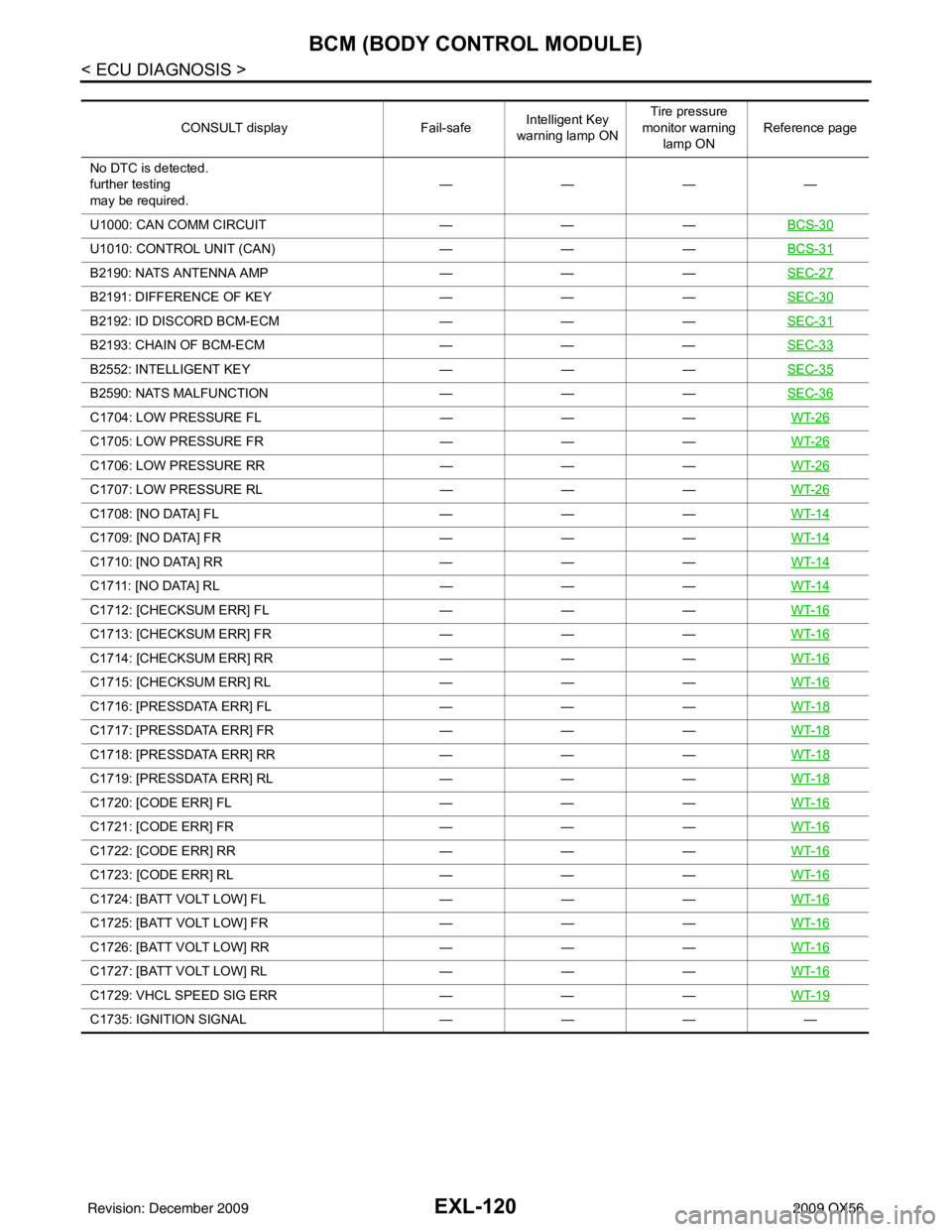
CONSULT displayFail-safeIntelligent Key
warning lamp ON Tire pressure
monitor warning lamp ON Reference page
No DTC is detected.
further testing
may be required. ————
U1000: CAN COMM CIRCUIT ———BCS-30
U1010: CONTROL UNIT (CAN) ———BCS-31
B2190: NATS ANTENNA AMP ———SEC-27
B2191: DIFFERENCE OF KEY ———SEC-30
B2192: ID DISCORD BCM-ECM ———SEC-31
B2193: CHAIN OF BCM-ECM ———SEC-33
B2552: INTELLIGENT KEY ———SEC-35
B2590: NATS MALFUNCTION ———SEC-36
C1704: LOW PRESSURE FL ———WT-26
C1705: LOW PRESSURE FR ———WT-26
C1706: LOW PRESSURE RR ———WT-26
C1707: LOW PRESSURE RL ———WT-26
C1708: [NO DATA] FL ———WT-14
C1709: [NO DATA] FR ———WT-14
C1710: [NO DATA] RR ———WT-14
C1711: [NO DATA] RL ———WT-14
C1712: [CHECKSUM ERR] FL ———WT-16
C1713: [CHECKSUM ERR] FR ———WT-16
C1714: [CHECKSUM ERR] RR ———WT-16
C1715: [CHECKSUM ERR] RL ———WT-16
C1716: [PRESSDATA ERR] FL ———WT-18
C1717: [PRESSDATA ERR] FR ———WT-18
C1718: [PRESSDATA ERR] RR ———WT-18
C1719: [PRESSDATA ERR] RL ———WT-18
C1720: [CODE ERR] FL ———WT-16
C1721: [CODE ERR] FR ———WT-16
C1722: [CODE ERR] RR ———WT-16
C1723: [CODE ERR] RL ———WT-16
C1724: [BATT VOLT LOW] FL ———WT-16
C1725: [BATT VOLT LOW] FR ———WT-16
C1726: [BATT VOLT LOW] RR ———WT-16
C1727: [BATT VOLT LOW] RL ———WT-16
C1729: VHCL SPEED SIG ERR ———WT-19
C1735: IGNITION SIGNAL ————
Revision: December 20092009 QX56
Page 2091 of 4171

ADJUSTMENT AND INSPECTIONEXL-143
< ON-VEHICLE REPAIR >
C
DE
F
G H
I
J
K
M A
B
EXL
N
O P
ON-VEHICLE REPAIR
ADJUSTMENT AND INSPECTION
HEADLAMP
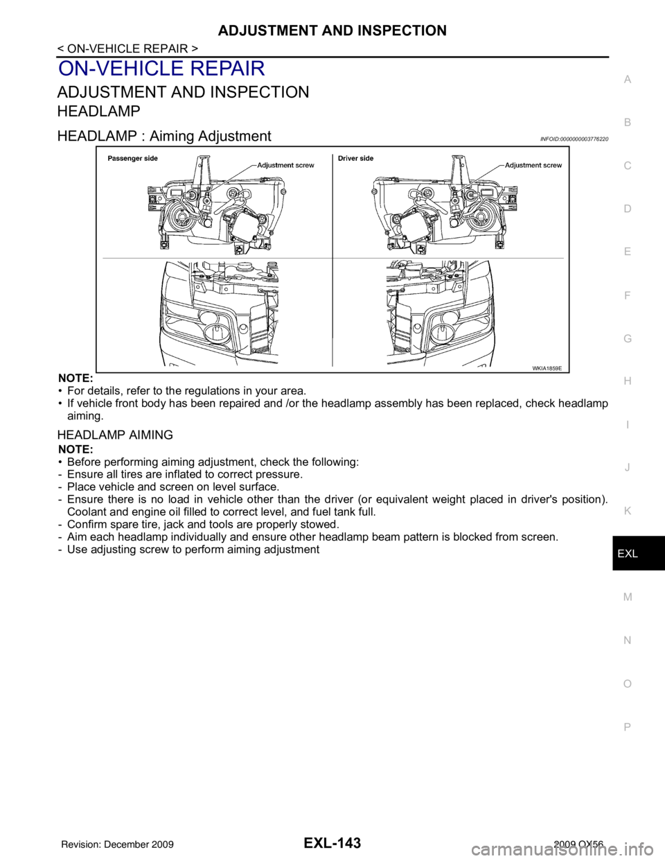
HEADLAMP : Aiming AdjustmentINFOID:0000000003776220
NOTE:
• For details, refer to the regulations in your area.
• If vehicle front body has been repaired and /or the headlamp assembly has been replaced, check headlamp
aiming.
HEADLAMP AIMING
NOTE:
• Before performing aiming adjustment, check the following:
- Ensure all tires are inflated to correct pressure.
- Place vehicle and screen on level surface.
- Ensure there is no load in vehicle other than the driver (or equivalent weight placed in driver's position). Coolant and engine oil filled to correct level, and fuel tank full.
- Confirm spare tire, jack and tools are properly stowed.
- Aim each headlamp individually and ensure other headlamp beam pattern is blocked from screen.
- Use adjusting screw to perform aiming adjustment
WKIA1859E
Revision: December 20092009 QX56
Page 2092 of 4171

EXL-144
< ON-VEHICLE REPAIR >
ADJUSTMENT AND INSPECTION
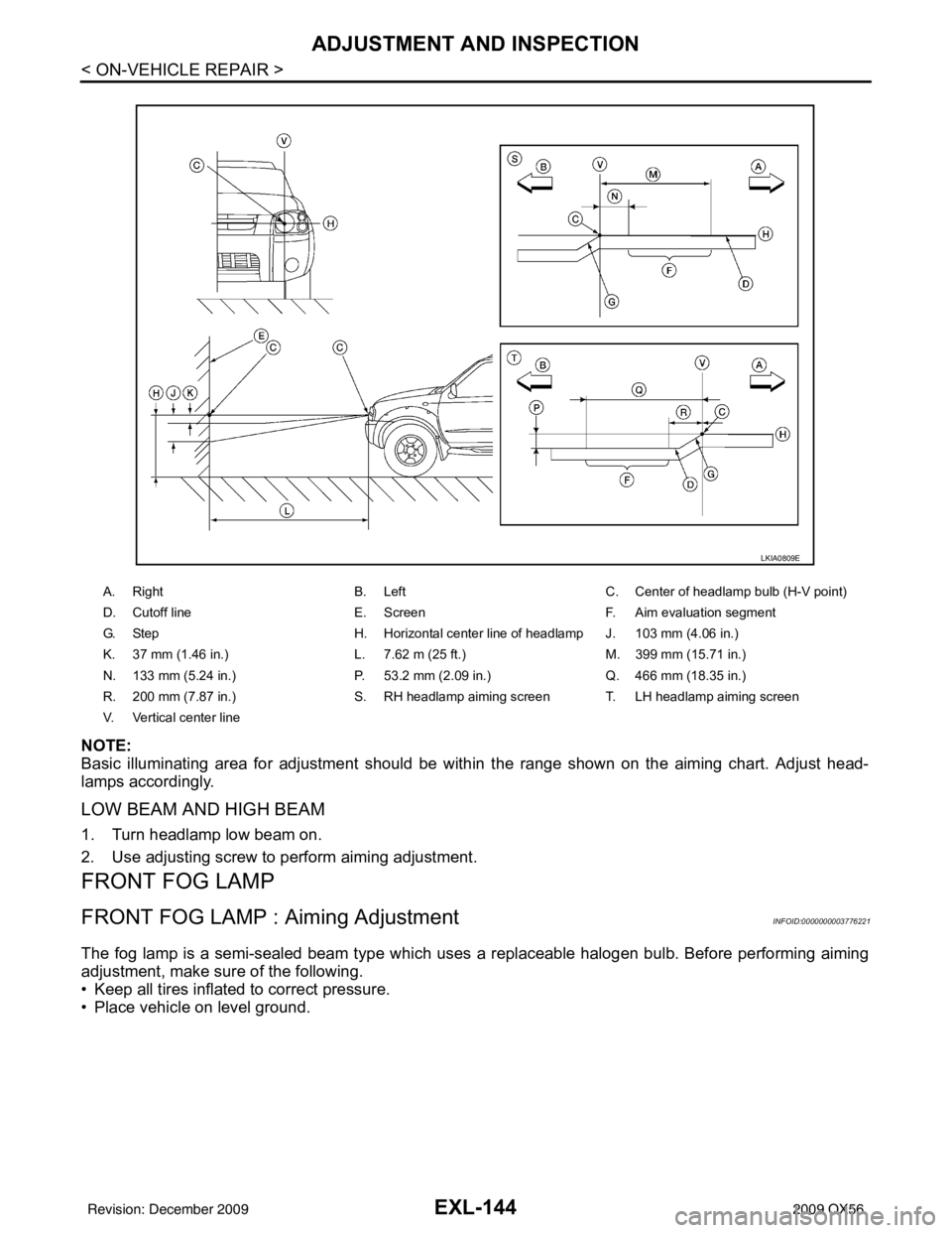
NOTE:
Basic illuminating area for adjustment should be within the range shown on the aiming chart. Adjust head-
lamps accordingly.
LOW BEAM AND HIGH BEAM
1. Turn headlamp low beam on.
2. Use adjusting screw to perform aiming adjustment.
FRONT FOG LAMP
FRONT FOG LAMP : Aiming AdjustmentINFOID:0000000003776221
The fog lamp is a semi-sealed beam type which uses a replaceable halogen bulb. Before performing aiming
adjustment, make sure of the following.
• Keep all tires inflated to correct pressure.
• Place vehicle on level ground.
A. RightB. Left C. Center of headlamp bulb (H-V point)
D. Cutoff line E. ScreenF. Aim evaluation segment
G. Step H. Horizontal center line of headlamp J. 103 mm (4.06 in.)
K. 37 mm (1.46 in.) L. 7.62 m (25 ft.) M. 399 mm (15.71 in.)
N. 133 mm (5.24 in.) P. 53.2 mm (2.09 in.)Q. 466 mm (18.35 in.)
R. 200 mm (7.87 in.) S. RH headlamp aiming screen T. LH headlamp aiming screen
V. Vertical center line
LKIA0809E
Revision: December 20092009 QX56
Page 2165 of 4171

FL-12
< REMOVAL AND INSTALLATION >
FUEL TANK
REMOVAL
WARNING:
Follow the “General Precautions” before working on the fuel system. Refer to FL-4, "
General Precau-
tion".
1. Remove the fuel filler cap to release the pressure from inside the fuel tank.
2. Release the fuel pressure from the fuel lines. Refer to EC-487, "
Fuel Pressure Check".
3. Drain the fuel from the fuel tank, if necessary.
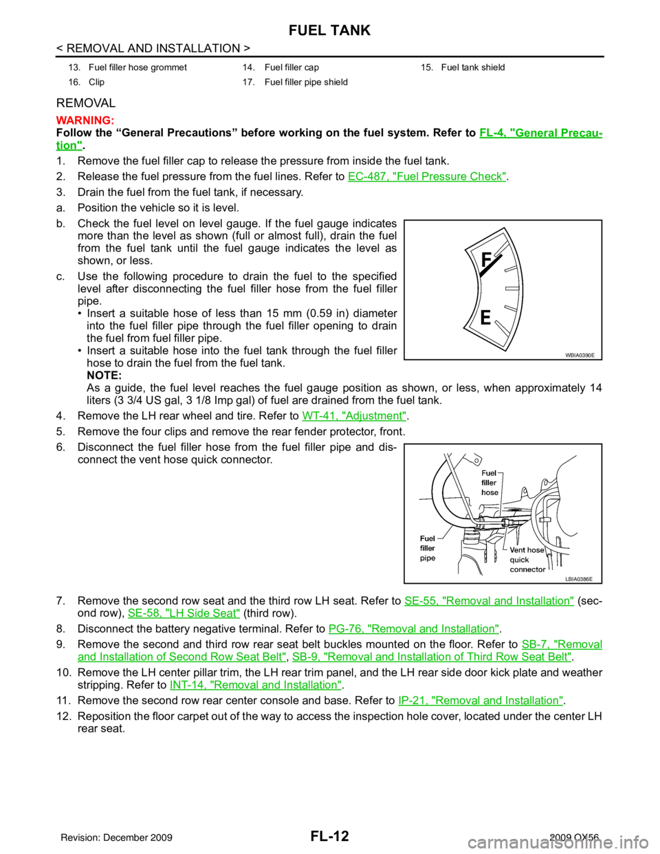
a. Position the vehicle so it is level.
b. Check the fuel level on level gauge. If the fuel gauge indicates more than the level as shown (full or almost full), drain the fuel
from the fuel tank until the fuel gauge indicates the level as
shown, or less.
c. Use the following procedure to drain the fuel to the specified level after disconnecting the fuel filler hose from the fuel filler
pipe.
• Insert a suitable hose of less than 15 mm (0.59 in) diameterinto the fuel filler pipe through the fuel filler opening to drain
the fuel from fuel filler pipe.
• Insert a suitable hose into the fuel tank through the fuel filler hose to drain the fuel from the fuel tank.
NOTE:
As a guide, the fuel level reaches the fuel gauge position as shown, or less, when approximately 14
liters (3 3/4 US gal, 3 1/8 Imp gal) of fuel are drained from the fuel tank.
4. Remove the LH rear wheel and tire. Refer to WT-41, "
Adjustment".
5. Remove the four clips and remove the rear fender protector, front.
6. Disconnect the fuel filler hose from the fuel filler pipe and dis- connect the vent hose quick connector.
7. Remove the second row seat and the third row LH seat. Refer to SE-55, "
Removal and Installation" (sec-
ond row), SE-58, "
LH Side Seat" (third row).
8. Disconnect the battery negative terminal. Refer to PG-76, "
Removal and Installation".
9. Remove the second and third row rear seat belt buckles mounted on the floor. Refer to SB-7, "
Removal
and Installation of Second Row Seat Belt", SB-9, "Removal and Installation of Third Row Seat Belt".
10. Remove the LH center pillar trim, the LH rear trim panel, and the LH rear side door kick plate and weather
stripping. Refer to INT-14, "
Removal and Installation".
11. Remove the second row rear center console and base. Refer to IP-21, "
Removal and Installation".
12. Reposition the floor carpet out of the way to access the inspection hole cover, located under the center LH
rear seat.
13. Fuel filler hose grommet 14. Fuel filler cap 15. Fuel tank shield
16. Clip 17. Fuel filler pipe shield
WBIA0390E
LBIA0386E
Revision: December 20092009 QX56