2009 INFINITI QX56 tire pressure
[x] Cancel search: tire pressurePage 2176 of 4171
FSU-6
< ON-VEHICLE MAINTENANCE >
ON-VEHICLE SERVICE
ON-VEHICLE MAINTENANCE
ON-VEHICLE SERVICE
Front Suspension PartsINFOID:0000000003772269
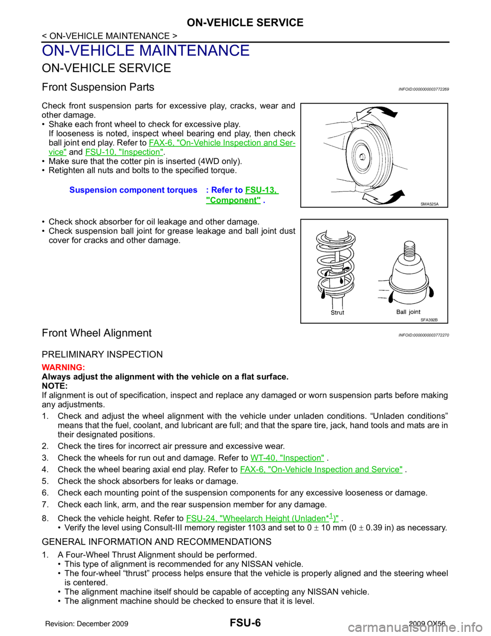
Check front suspension parts for excessive play, cracks, wear and
other damage.
• Shake each front wheel to check for excessive play.If looseness is noted, inspect wheel bearing end play, then check
ball joint end play. Refer to FA X - 6 , "
On-Vehicle Inspection and Ser-
vice" and FSU-10, "Inspection".
• Make sure that the cotter pin is inserted (4WD only).
• Retighten all nuts and bolts to the specified torque.
• Check shock absorber for oil leakage and other damage.
• Check suspension ball joint for grease leakage and ball joint dust cover for cracks and other damage.
Front Wheel AlignmentINFOID:0000000003772270
PRELIMINARY INSPECTION
WARNING:
Always adjust the alignment with the vehicle on a flat surface.
NOTE:
If alignment is out of specificat ion, inspect and replace any damaged or worn suspension parts before making
any adjustments.
1. Check and adjust the wheel alignment with the vehicle under unladen conditions. “Unladen conditions”
means that the fuel, coolant, and lubricant are full; and that the spare tire, jack, hand tools and mats are in
their designated positions.
2. Check the tires for incorrect air pressure and excessive wear.
3. Check the wheels for run out and damage. Refer to WT-40, "
Inspection" .
4. Check the wheel bearing axial end play. Refer to FA X - 6 , "
On-Vehicle Inspection and Service" .
5. Check the shock absorbers for leaks or damage.
6. Check each mounting point of the suspension components for any excessive looseness or damage.
7. Check each link, arm, and the rear suspension member for any damage.
8. Check the vehicle height. Refer to FSU-24, "
Wheelarch Height (Unladen*1)" .
• Verify the level using Consult-III memory register 1103 and set to 0 ± 10 mm (0 ± 0.39 in) as necessary.
GENERAL INFORMATION AND RECOMMENDATIONS
1. A Four-Wheel Thrust Alignment should be performed.
• This type of alignment is recommended for any NISSAN vehicle.
• The four-wheel “thrust” process helps ensure that the vehicle is properly aligned and the steering wheel
is centered.
• The alignment machine itself should be ca pable of accepting any NISSAN vehicle.
• The alignment machine should be checked to ensure that it is level. Suspension component
torques : Refer to FSU-13,
"Component" . SMA525A
SFA392B
Revision: December 20092009 QX56
Page 2295 of 4171
COMPRESSORHA-31
< ON-VEHICLE REPAIR >
C
DE
F
G H
J
K L
M A
B
HA
N
O P
COMPRESSOR
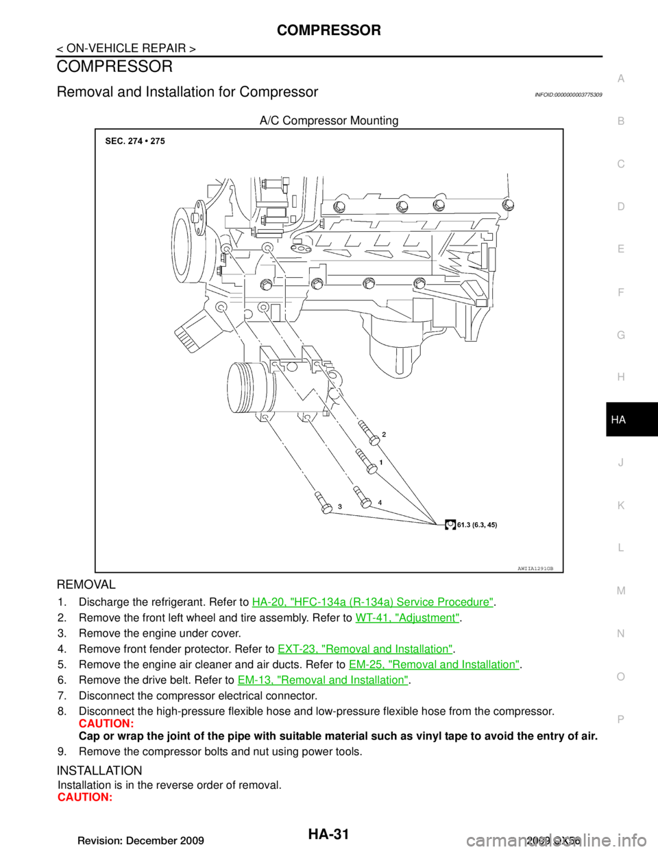
Removal and Installation for CompressorINFOID:0000000003775309
A/C Compressor Mounting
REMOVAL
1. Discharge the refrigerant. Refer to HA-20, "HFC-134a (R-134a) Service Procedure".
2. Remove the front left wheel and tire assembly. Refer to WT-41, "Adjustment"
.
3. Remove the engine under cover.
4. Remove front fender protector. Refer to EXT-23, "Removal and Installation"
.
5. Remove the engine air cleaner and air ducts. Refer to EM-25, "Removal and Installation"
.
6. Remove the drive belt. Refer to EM-13, "Removal and Installation"
.
7. Disconnect the compressor electrical connector.
8. Disconnect the high-pressure flexible hose and low-pressure flexible hose from the compressor. CAUTION:
Cap or wrap the joint of the pipe with suitable mate rial such as vinyl tape to avoid the entry of air.
9. Remove the compressor bolts and nut using power tools.
INSTALLATION
Installation is in the reverse order of removal.
CAUTION:
AWIIA1291GB
Revision: December 20092009 QX56
Page 2303 of 4171

LOW-PRESSURE PIPEHA-39
< ON-VEHICLE REPAIR >
C
DE
F
G H
J
K L
M A
B
HA
N
O P
5. Remove the front and rear bumper fascia. Refer to EXT-13, "Removal and Installation" (front), EXT-15,
"Removal and Installation" (rear).
6. Reposition the front fender protec tor out of the way. Refer to EXT-23, "Removal and Installation"
.
7. Disconnect the chassis harness connector.
8. Remove the spare wheel and tire.
9. Remove the tailpipe and tailpipe hanger bracket. Refer to EX-6, "Removal and Installation"
.
10. Remove the seatbelt latch anchor. Refer to EX-6, "Removal and Installation"
.
11. Remove the front floor heat shield.
12. Disconnect each end of the underfloor rear high- and low-pressure A/C and heater core pipes. Refer to
HA-29, "Component"
.
CAUTION:
Cap or wrap the joint of the pipes with suitable material such as viny l tape to avoid the entry of air.
13. Set two suitable jacks at the RH body mount points to support the vehicle body when it is separated from the RH side of the frame.
14. Remove the RH body mount bolts. Refer to BRM-6, "Body Mounting"
.
15. Use the vehicle hoist to lower the RH side of the frame from the RH side of the body [approximately 305
mm (12 in)] until there is suffici ent clearance to remove the underfloor rear high- and low-pressure A/C
and heater core pipes from between the body and the frame.
16. Remove the underfloor rear high- and low-pressure A/ C and heater core pipes from the back of the vehi-
cle.
INSTALLATION
Installation is in the reverse order of removal.
CAUTION:
Replace the O-rings of the underfloor rear high - and low-pressure A/C and heater core pipes with
new ones, then apply compressor oil to them for installation.
After charging refrigerant, check for leaks.
Revision: December 20092009 QX56
Page 2305 of 4171
HIGH-PRESSURE PIPEHA-41
< ON-VEHICLE REPAIR >
C
DE
F
G H
J
K L
M A
B
HA
N
O P
HIGH-PRESSURE PIPE
Removal and Installation for High-Pressure PipeINFOID:0000000003775316
REMOVAL
1. Remove the cowl top extension. Refer to EXT-18, "Removal and Installation".
2. Disconnect the battery negative termi nal and positive battery terminal.
3. Reposition the IPDM E/R aside.
4. Remove the front left wheel and tire assembly. Refer to MA-29, "Rotation"
.
5. Position aside the front floor insulator.
6. Discharge the refrigerant. Refer to HA-20, "HFC-134a (R-134a) Service Procedure"
.
7. Remove the low pressure pipe. Refer to HA-37, "Removal and Installation for Low-Pressure Pipe"
.
8. Remove the high-pressure pipe. CAUTION:
Cap or wrap the joint of the pipe with suitable mate rial such as vinyl tape to avoid the entry of air.
INSTALLATION
Installation is in the reverse order of removal.
Refer to HA-29, "Component"
.
CAUTION:
Replace the O-ring of the high-pressure pipe with a new one, then apply compressor oil to it when
installing it.
After charging refrigerant, check for leaks.
Removal and Installation for Rear High- and Low-Pressure A/C and Heater Core Pipes
INFOID:0000000003775317
REMOVAL
1. Discharge the refrigerant from the A/C system. Refer to HA-20, "HFC-134a (R-134a) Service Procedure".
2. Drain the coolant from the engine cooling system. Refer to CO-11, "Changing Engine Coolant"
.
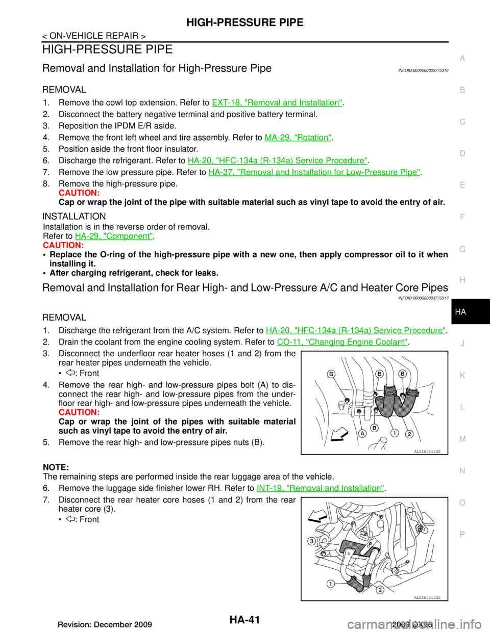
3. Disconnect the underfloor rear heater hoses (1 and 2) from the rear heater pipes underneath the vehicle.
: Front
4. Remove the rear high- and low-pressure pipes bolt (A) to dis- connect the rear high- and low-pressure pipes from the under-
floor rear high- and low-pressu re pipes underneath the vehicle.
CAUTION:
Cap or wrap the joint of the pipes with suitable material
such as vinyl tape to avoid the entry of air.
5. Remove the rear high- and low-pressure pipes nuts (B).
NOTE:
The remaining steps are performed inside the rear luggage area of the vehicle.
6. Remove the luggage side finisher lower RH. Refer to INT-19, "Removal and Installation"
.
7. Disconnect the rear heater core hoses (1 and 2) from the rear heater core (3).
: Front
ALIIA0216ZZ
ALIIA0218ZZ
Revision: December 20092009 QX56
Page 2307 of 4171
HIGH-PRESSURE PIPEHA-43
< ON-VEHICLE REPAIR >
C
DE
F
G H
J
K L
M A
B
HA
N
O P
5. Remove the front and rear bumper fascia. Refer to EXT-13, "Removal and Installation" (front), EXT-15,
"Removal and Installation" (rear).
6. Reposition the front fender protec tor out of the way. Refer to EXT-23, "Removal and Installation"
.
7. Disconnect the chassis harness connector.
8. Remove the spare wheel and tire.
9. Remove the tailpipe and tailpipe hanger bracket. Refer to EX-6, "Removal and Installation"
.
10. Remove the seatbelt latch anchor. Refer to EX-6, "Removal and Installation"
.
11. Remove the front floor heat shield.
12. Disconnect each end of the underfloor rear high- and low-pressure A/C and heater core pipes. Refer to
HA-29, "Component"
.
CAUTION:
Cap or wrap the joint of the pipes with suitable material such as viny l tape to avoid the entry of air.
13. Set two suitable jacks at the RH body mount points to support the vehicle body when it is separated from the RH side of the frame.
14. Remove the RH body mount bolts. Refer to BRM-6, "Body Mounting"
.
15. Use the vehicle hoist to lower the RH side of the frame from the RH side of the body [approximately 305
mm (12 in)] until there is suffici ent clearance to remove the underfloor rear high- and low-pressure A/C
and heater core pipes from between the body and the frame.
16. Remove the underfloor rear high- and low-pressure A/ C and heater core pipes from the back of the vehi-
cle.
INSTALLATION
Installation is in the reverse order of removal.
CAUTION:
Replace the O-rings of the underfloor rear high - and low-pressure A/C and heater core pipes with
new ones, then apply compressor oil to them for installation.
After charging refrigerant, check for leaks.
Revision: December 20092009 QX56
Page 2334 of 4171
![INFINITI QX56 2009 Factory Service Manual DIAGNOSIS SYSTEM (BCM)HAC-21
< FUNCTION DIAGNOSIS > [AUTOMATIC AIR CONDITIONER]
C
D
E
F
G H
J
K L
M A
B
HAC
N
O P
DIAGNOSIS SYSTEM (BCM)
CONSULT-III Function (BCM - COMMON ITEM)INFOID:0000000004335398 INFINITI QX56 2009 Factory Service Manual DIAGNOSIS SYSTEM (BCM)HAC-21
< FUNCTION DIAGNOSIS > [AUTOMATIC AIR CONDITIONER]
C
D
E
F
G H
J
K L
M A
B
HAC
N
O P
DIAGNOSIS SYSTEM (BCM)
CONSULT-III Function (BCM - COMMON ITEM)INFOID:0000000004335398](/manual-img/42/57031/w960_57031-2333.png)
DIAGNOSIS SYSTEM (BCM)HAC-21
< FUNCTION DIAGNOSIS > [AUTOMATIC AIR CONDITIONER]
C
D
E
F
G H
J
K L
M A
B
HAC
N
O P
DIAGNOSIS SYSTEM (BCM)
CONSULT-III Function (BCM - COMMON ITEM)INFOID:0000000004335398
APPLICATION ITEM
CONSULT-III performs the following functions via CAN communication with BCM.
SYSTEM APPLICATION
BCM can perform the following functions for each system.
NOTE:
It can perform the diagnosis modes except the following for all sub system selection items.
CONSULT-III Function (BCM - AUTO AIR CONDITIONER)INFOID:0000000004335399
DATA MONITOR
Diagnosis mode Function Description
WORK SUPPORT Changes the setting for each system function.
SELF-DIAG RESULTS Displays the diagnosis results judged by BCM. Refer to BCS-51, "
DTCIndex".
CAN DIAG SUPPORT MNTR Monitors the reception status of CAN communication viewed from BCM.
DATA MONITOR The BCM input/output signals are displayed.
ACTIVE TEST The signals used to activate each device are forcibly supplied from BCM.
ECU IDENTIFICATION The BCM pa rt number is displayed.
CONFIGURATION • Enables to read and save the vehicle specification.
• Enables to write the vehicle specification when replacing BCM.
System
Sub system selection item Diagnosis mode
WORK SUPPORT DATA MONITOR ACTIVE TEST
BCM BCM ×
Door lock DOOR LOCK ×××
Rear window defogger REAR DEFOGGER ×
Warning chime BUZZER ××
Interior room lamp timer INT LAMP ×××
Remote keyless entry system MULTI REMOTE ENT ××
Exterior lamp HEAD LAMP ×××
Wiper and washer WIPER ×××
Turn signal and hazard warning lamps FLASHER ××
Air conditioner AIR CONDITONER ×
Intelligent Key system INTELLIGENT KEY ×
Combination switch COMB SW ×
Immobilizer IMMU ××
Interior room lamp battery saver BATTERY SAVER ×××
Back door open TRUNK ××
RAP (retained accessory power) RETAINED PWR ×××
Signal buffer system SIGNAL BUFFER ××
TPMS (tire pressure monitoring sys-
tem) AIR PRESSURE MONITOR
×××
Vehicle security system PANIC ALARM ×
Revision: December 20092009 QX56
Page 2455 of 4171
DIAGNOSIS SYSTEM (BCM)INL-11
< FUNCTION DIAGNOSIS >
C
DE
F
G H
I
J
K
M A
B
INL
N
O P
DIAGNOSIS SYSTEM (BCM)
COMMON ITEM
COMMON ITEM : CONSULT-III Fu nction (BCM - COMMON ITEM)INFOID:0000000004109547
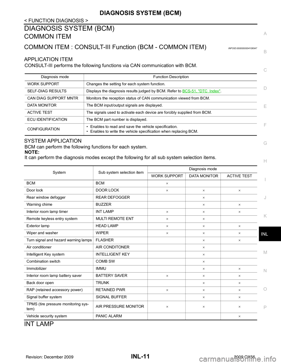
APPLICATION ITEM
CONSULT-III performs the following functions via CAN communication with BCM.
SYSTEM APPLICATION
BCM can perform the following functions for each system.
NOTE:
It can perform the diagnosis modes except the following for all sub system selection items.
INT LAMP
Diagnosis mode Function Description
WORK SUPPORT Changes the setting for each system function.
SELF-DIAG RESULTS Displays the diagnosis results judged by BCM. Refer to BCS-51, "
DTCIndex".
CAN DIAG SUPPORT MNTR Monitors the reception status of CAN communication viewed from BCM.
DATA MONITOR The BCM input/output signals are displayed.
ACTIVE TEST The signals used to activate each device are forcibly supplied from BCM.
ECU IDENTIFICATION The BCM pa rt number is displayed.
CONFIGURATION • Enables to read and save the vehicle specification.
• Enables to write the vehicle specification when replacing BCM.
System
Sub system selection item Diagnosis mode
WORK SUPPORT DATA MONITOR ACTIVE TEST
BCM BCM ×
Door lock DOOR LOCK ×××
Rear window defogger REAR DEFOGGER ×
Warning chime BUZZER ××
Interior room lamp timer INT LAMP ×××
Remote keyless entry system MULTI REMOTE ENT ××
Exterior lamp HEAD LAMP ×××
Wiper and washer WIPER ×××
Turn signal and hazard warning lamps FLASHER ××
Air conditioner AIR CONDITONER ×
Intelligent Key system INTELLIGENT KEY ×
Combination switch COMB SW ×
Immobilizer IMMU ××
Interior room lamp battery saver BATTERY SAVER ×××
Back door open TRUNK ××
RAP (retained accessory power) RETAINED PWR ×××
Signal buffer system SIGNAL BUFFER ××
TPMS (tire pressure monitoring sys-
tem) AIR PRESSURE MONITOR
×××
Vehicle security system PANIC ALARM ×
Revision: December 20092009 QX56
Page 2502 of 4171
INL-58
< ECU DIAGNOSIS >
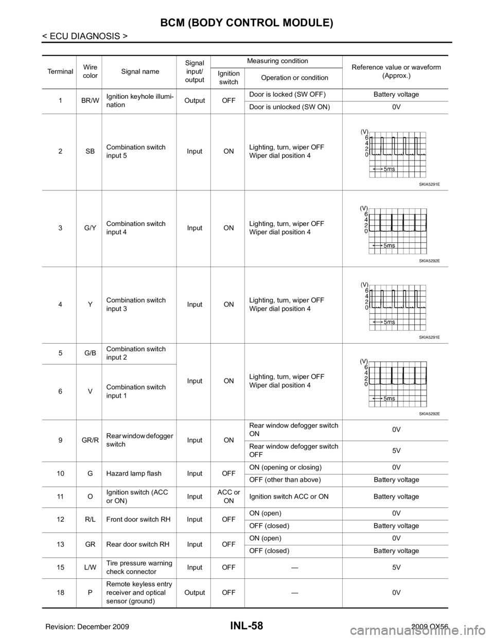
BCM (BODY CONTROL MODULE)
Te r m i n a lWire
color Signal name Signal
input/
output Measuring condition
Reference value or waveform
(Approx.)
Ignition
switch Operation or condition
1BR/W Ignition keyhole illumi-
nation Output OFFDoor is locked (SW OFF)
Battery voltage
Door is unlocked (SW ON) 0V
2SB Combination switch
input 5 Input ON
Lighting, turn, wiper OFF
Wiper dial position 4
3G/Y Combination switch
input 4 Input ONLighting, turn, wiper OFF
Wiper dial position 4
4Y Combination switch
input 3 Input ON
Lighting, turn, wiper OFF
Wiper dial position 4
5G/B Combination switch
input 2
Input ONLighting, turn, wiper OFF
Wiper dial position 4
6V Combination switch
input 1
9GR/R Rear window defogger
switch
Input ONRear window defogger switch
ON
0V
Rear window defogger switch
OFF 5V
10 G Hazard lamp flash Input OFF ON (opening or closing)
0V
OFF (other than above) Battery voltage
11 O Ignition switch (ACC
or ON)
InputACC or
ON Ignition switch ACC or ON
Battery voltage
12 R/L Front door switch RH Input OFF ON (open)
0V
OFF (closed) Battery voltage
13 GR Rear door switch RH Input OFF ON (open)
0V
OFF (closed) Battery voltage
15 L/W Tire pressure warning
check connector
Input OFF
—5V
18 P Remote keyless entry
receiver and optical
sensor (ground)
Output OFF
—0V
SKIA5291E
SKIA5292E
SKIA5291E
SKIA5292E
Revision: December 20092009 QX56