Page 3852 of 4171
TM-204
< ON-VEHICLE REPAIR >
CONTROL VALVE WITH TCM
4. Remove snap ring from A/T assembly harness connector.
5. Push A/T assembly harness connector.CAUTION:
Do not damage connector.
6. Remove oil pan and oil pan gasket. Refer to TM-201, "Oil Pan"
.
7. Disconnect A/T fluid temperat ure sensor 2 connector (A).
CAUTION:
Do not damage connector.
8. Straighten the four terminal clips to free the terminal cord assembly for A/T fluid temperature sensor 2 harness.
: Terminal clip
9. Straighten terminal clip to fr ee the output speed sensor harness.
10. Disconnect output speed sensor connector (1). CAUTION:
Do not damage connector.
SCIA5021E
SCIA5022E
SCIA8124E
JSDIA1316ZZ
Revision: December 20092009 QX56
Page 3857 of 4171

CONTROL VALVE WITH TCMTM-209
< ON-VEHICLE REPAIR >
CEF
G H
I
J
K L
M A
B
TM
N
O P
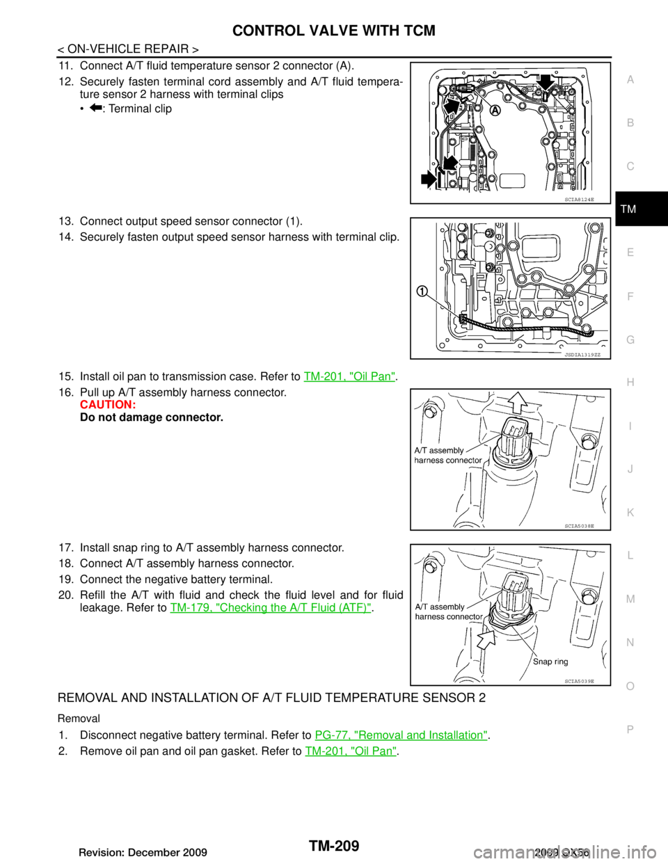
11. Connect A/T fluid temperature sensor 2 connector (A).
12. Securely fasten terminal cord assembly and A/T fluid tempera- ture sensor 2 harness with terminal clips
: Terminal clip
13. Connect output speed sensor connector (1).
14. Securely fasten output speed sensor harness with terminal clip.
15. Install oil pan to transmission case. Refer to TM-201, "Oil Pan"
.
16. Pull up A/T assembly harness connector. CAUTION:
Do not damage connector.
17. Install snap ring to A/T assembly harness connector.
18. Connect A/T assembly harness connector.
19. Connect the negative battery terminal.
20. Refill the A/T with fluid and check the fluid level and for fluid leakage. Refer to TM-179, "Checking the A/T Fluid (ATF)"
.
REMOVAL AND INSTALLATION OF A/ T FLUID TEMPERATURE SENSOR 2
Removal
1. Disconnect negative battery terminal. Refer to PG-77, "Removal and Installation".
2. Remove oil pan and oil pan gasket. Refer to TM-201, "Oil Pan"
.
SCIA8124E
JSDIA1319ZZ
SCIA5038E
SCIA5039E
Revision: December 20092009 QX56
Page 3859 of 4171
CONTROL VALVE WITH TCMTM-211
< ON-VEHICLE REPAIR >
CEF
G H
I
J
K L
M A
B
TM
N
O P
2. Install A/T fluid temperature sens or 2 (with bracket) in control
valve with TCM. Tighten A/T flui d temperature sensor 2 bolt to
the specified torque. Refer to TM-203, "Control Valve with TCM
and A/T Fluid Temperature Sensor 2".
CAUTION:
Adjust bolt hole of bracket to bolt hole of control valve with
TCM.
3. Connect A/T fluid temperature sensor 2 connector (A).
4. Securely fasten A/T fluid temperature sensor 2 harness with ter- minal clip .
5. Install oil pan to transmission case. Refer to TM-201, "Oil Pan"
.
6. Connect the negative battery terminal. Refer to PG-77, "Removal and Installation"
.
7. Refill the A/T with fluid and check the fluid level and for fluid leakage. Refer to TM-179, "Checking the A/T
Fluid (ATF)".
SCIA5253E
SCIA8125E
Revision: December 20092009 QX56
Page 3860 of 4171

TM-212
< ON-VEHICLE REPAIR >
REAR OIL SEAL
REAR OIL SEAL
Rear Oil SealINFOID:0000000004187482
REMOVAL AND INSTALLATION
Removal
1. Remove rear propeller shaft. Refer to DLN-196, "Removal and Installation".
2. Remove transfer from transmission (4WD models). Refer to DLN-141, "Removal and Installation"
.
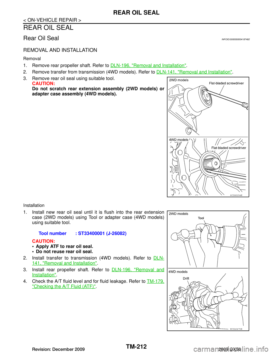
3. Remove rear oil seal using suitable tool. CAUTION:
Do not scratch rear extension assembly (2WD models) or
adapter case assembly (4WD models).
Installation
1. Install new rear oil seal until it is flush into the rear extension
case (2WD models) using Tool or adapter case (4WD models)
using suitable tool.
CAUTION:
Apply ATF to rear oil seal.
Do not reuse rear oil seal.
2. Install transfer to transmission (4WD models). Refer to DLN-
141, "Removal and Installation".
3. Install rear propeller shaft. Refer to DLN-196, "Removal and
Installation".
4. Check the A/T fluid level and for fluid leakage. Refer to TM-179,
"Checking the A/T Fluid (ATF)".
SCIA5254E
Tool number : ST33400001 (J-26082)
WCIA0475E
Revision: December 20092009 QX56
Page 3864 of 4171

TM-216
< REMOVAL AND INSTALLATION >
TRANSMISSION ASSEMBLY
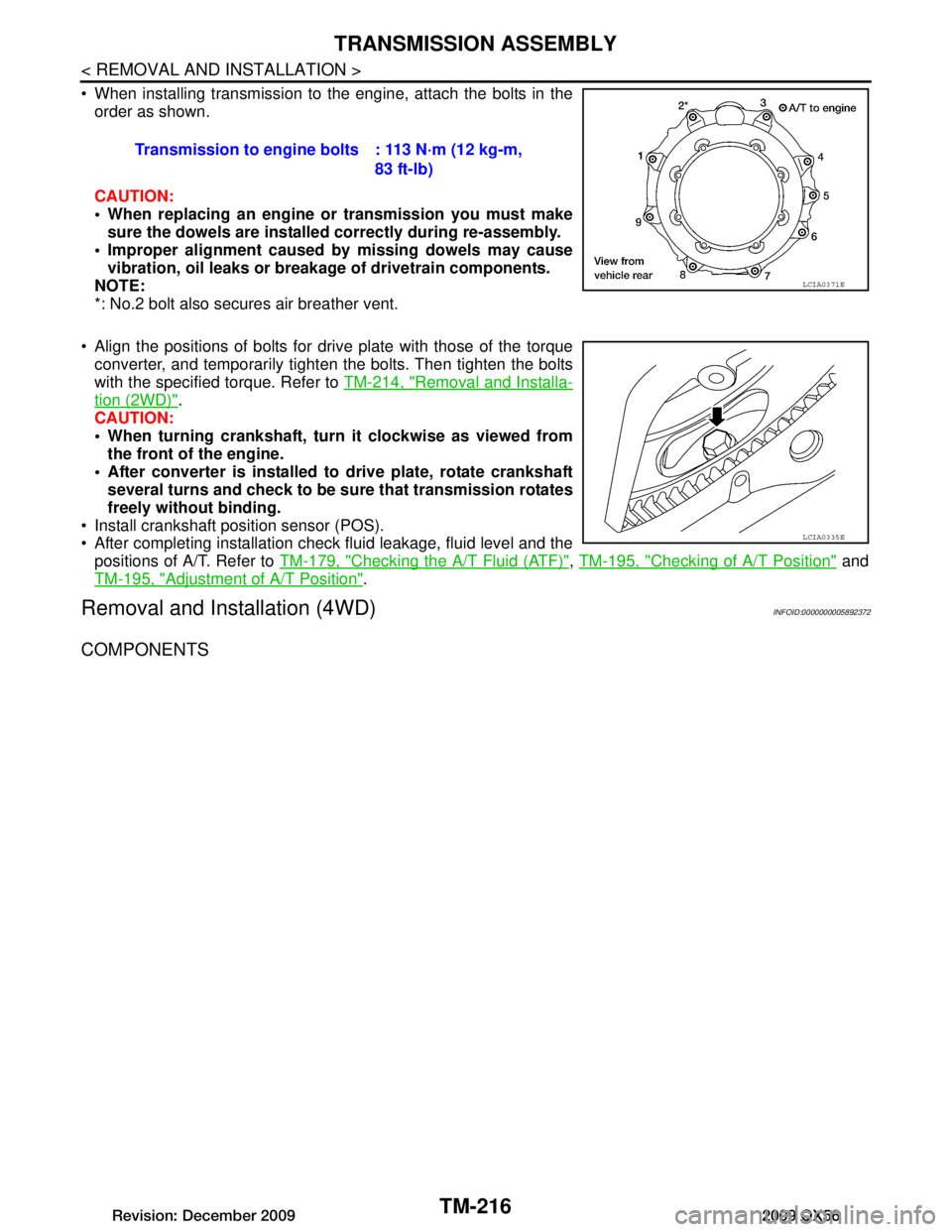
When installing transmission to the engine, attach the bolts in theorder as shown.
CAUTION:
When replacing an engine or transmission you must make
sure the dowels are installe d correctly during re-assembly.
Improper alignment caused by missing dowels may cause
vibration, oil leaks or breakage of drivetrain components.
NOTE:
*: No.2 bolt also secures air breather vent.
Align the positions of bolts for drive plate with those of the torque converter, and temporarily tight en the bolts. Then tighten the bolts
with the specified torque. Refer to TM-214, "Removal and Installa-
tion (2WD)".
CAUTION:
When turning crankshaft, turn it clockwise as viewed from
the front of the engine.
After converter is installed to drive plate, rotate crankshaft several turns and check to be su re that transmission rotates
freely without binding.
Install crankshaft position sensor (POS).
After completing installation check fluid leakage, fluid level and the positions of A/T. Refer to TM-179, "Checking the A/T Fluid (ATF)"
, TM-195, "Checking of A/T Position" and
TM-195, "Adjustment of A/T Position"
.
Removal and Installation (4WD)INFOID:0000000005892372
COMPONENTS
Transmission to engine bolts : 113 N·m (12 kg-m,
83 ft-lb)
LCIA0371E
LCIA0335E
Revision: December 20092009 QX56
Page 3867 of 4171

TRANSMISSION ASSEMBLYTM-219
< REMOVAL AND INSTALLATION >
CEF
G H
I
J
K L
M A
B
TM
N
O P
INSPECTION
Installation and Inspection of Torque Converter
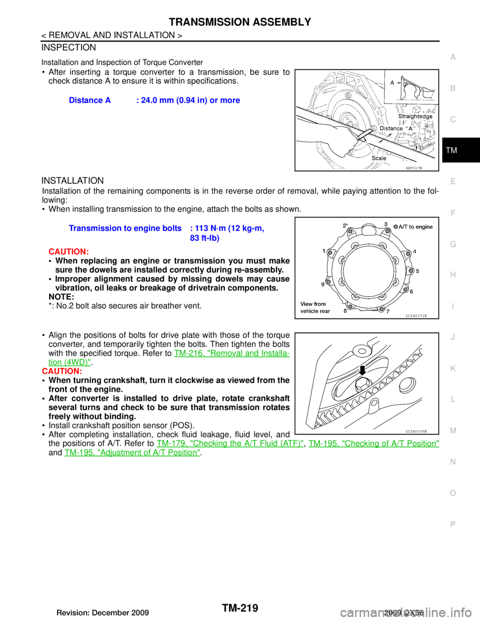
After inserting a torque converter to a transmission, be sure to check distance A to ensure it is within specifications.
INSTALLATION
Installation of the remaining components is in the revers e order of removal, while paying attention to the fol-
lowing:
When installing transmission to the engine, attach the bolts as shown.
CAUTION:
When replacing an engine or transmission you must make sure the dowels are installed correctly during re-assembly.
Improper alignment caused by missing dowels may cause vibration, oil leaks or breakage of drivetrain components.
NOTE:
*: No.2 bolt also secures air breather vent.
Align the positions of bolts for dr ive plate with those of the torque
converter, and temporarily tighten the bolts. Then tighten the bolts
with the specified torque. Refer to TM-216, "Removal and Installa-
tion (4WD)".
CAUTION:
When turning crankshaft, turn it clockwise as viewed from the
front of the engine.
After converter is installed to drive plate, rotate crankshaft
several turns and check to be sure that transmission rotates
freely without binding.
Install crankshaft position sensor (POS).
After completing installation, check fluid leakage, fluid level, and the positions of A/T. Refer to TM-179, "Checking the A/T Fluid (ATF)"
, TM-195, "Checking of A/T Position"
and TM-195, "Adjustment of A/T Position".
Distance A : 24.0 mm (0.94 in) or more
SAT017B
Transmission to engine bolts : 113 N·m (12 kg-m,
83 ft-lb)
LCIA0371E
LCIA0335E
Revision: December 20092009 QX56
Page 3869 of 4171
OVERHAULTM-221
< DISASSEMBLY AND ASSEMBLY >
CEF
G H
I
J
K L
M A
B
TM
N
O P
1. O-ring 2. Oil pump cover 3. O-ring
4. Oil pump housing 5. Self-sealing bolts 6. Torque converter
7. Converter housing 8. Oil pump housing oil seal 9. Bearing race
10. Needle bearing 11. O-ring 12. Front carrier assembly
13. Needle bearing 14. Snap ring 15. Front sun gear
16. 3rd one-way clutch 17. Snap ring 18. Bearing race
19. Needle bearing 20. Seal ring 21. Input clutch assembly
22. Needle bearing 23. Rear internal gear 24. Brake band
25. Mid carrier assembly 26. Needle bearing 27. Bearing race
28. Rear carrier assembly 29. Needle bearing 30. Mid sun gear
31. Seal ring 32. Rear sun gear 33. 1st one-way clutch
34. Snap ring 35. Needle bearing 36. High and low reverse clutch hub
37. Snap ring 38. Bearing race 39. Needle bearing
Revision: December 20092009 QX56
Page 3871 of 4171
OVERHAULTM-223
< DISASSEMBLY AND ASSEMBLY >
CEF
G H
I
J
K L
M A
B
TM
N
O P
2WD
1. Rear oil seal 2. Bracket 3. Bracket
4. Adapter case 5. Parking actuator support 6. Parking pawl
7. Return spring 8. Pawl shaft 9. Self-sealing bolt
10. Seal ring 11. Needle bearing 12. Gasket
13. Output speed sensor 14. Parking gear 15. Output shaft
AWDIA0027GB
Revision: December 20092009 QX56