2009 INFINITI QX56 display
[x] Cancel search: displayPage 3406 of 4171
![INFINITI QX56 2009 Factory Service Manual SEC-96
< ECU DIAGNOSIS >[WITH INTELLIGENT KEY SYSTEM]
IPDM E/R (INTELLIGENT POWER DI
STRIBUTION MODULE ENGINE ROOM)
IPDM E/R (INTELLIGENT POWER DISTRIBUTION MODULE ENGINE
ROOM)
Reference ValueINFOID: INFINITI QX56 2009 Factory Service Manual SEC-96
< ECU DIAGNOSIS >[WITH INTELLIGENT KEY SYSTEM]
IPDM E/R (INTELLIGENT POWER DI
STRIBUTION MODULE ENGINE ROOM)
IPDM E/R (INTELLIGENT POWER DISTRIBUTION MODULE ENGINE
ROOM)
Reference ValueINFOID:](/manual-img/42/57031/w960_57031-3405.png)
SEC-96
< ECU DIAGNOSIS >[WITH INTELLIGENT KEY SYSTEM]
IPDM E/R (INTELLIGENT POWER DI
STRIBUTION MODULE ENGINE ROOM)
IPDM E/R (INTELLIGENT POWER DISTRIBUTION MODULE ENGINE
ROOM)
Reference ValueINFOID:0000000004221479
VALUES ON THE DIAGNOSIS TOOL
Monitor Item ConditionValue/Status
MOTOR FAN REQ Engine idle speed Changes depending on engine
coolant temperature, air conditioner
operation status, vehicle speed,
etc.0 - 100 %
A/C COMP REQ A/C switch OFF
OFF
A/C switch ON ON
TAIL&CLR REQ Lighting switch OFF
OFF
Lighting switch 1ST, 2ND, HI or AUTO (Light is illuminated) ON
HL LO REQ Lighting switch OFF
OFF
Lighting switch 2ND HI or AUTO (Light is illuminated) ON
HL HI REQ Lighting switch OFF
OFF
Lighting switch HI ON
FR FOG REQ Lighting switch 2ND or AUTO (Light
is illuminated) Front fog lamp switch OFF OFF
• Front fog lamp switch ON
• Daytime light activated (Canada
only) ON
HL WASHER REQ NOTE:
This item is displayed, but cannot be monitored.
OFF
FR WIP REQ Ignition switch ON Front wiper switch OFF
STOP
Front wiper switch INT 1LOW
Front wiper switch LO LOW
Front wiper switch HI HI
WIP AUTO STOP Ignition switch ON Front wiper stop position
STOP P
Any position other than front wiper
stop position ACT P
WIP PROT Ignition switch ON Front wiper operates normally OFF
Front wiper stops at fail-safe opera-
tion
BLOCK
ST RLY REQ Ignition switch OFF or ACC
OFF
Ignition switch START ON
IGN RLY Ignition switch OFF or ACC
OFF
Ignition switch ON ON
RR DEF REQ Rear defogger switch OFF
OFF
Rear defogger switch ON ON
OIL P SW Ignition switch OFF, ACC or engine running
OPEN
Ignition switch ON CLOSE
DTRL REQ Daytime light system requested OFF with CONSULT-III.
OFF
Daytime light system requested ON with CONSULT-III. ON
HOOD SW Hood closed.
OFF
Hood open. ON
Revision: December 20092009 QX56
Page 3413 of 4171
![INFINITI QX56 2009 Factory Service Manual IPDM E/R (INTELLIGENT POWER DISTRIBUTION MODULE ENGINE ROOM)
SEC-103
< ECU DIAGNOSIS > [WITH INTELLIGENT KEY SYSTEM]
C
D
E
F
G H
I
J
L
M A
B
SEC
N
O P
When a front wiper auto stop signal is in the con INFINITI QX56 2009 Factory Service Manual IPDM E/R (INTELLIGENT POWER DISTRIBUTION MODULE ENGINE ROOM)
SEC-103
< ECU DIAGNOSIS > [WITH INTELLIGENT KEY SYSTEM]
C
D
E
F
G H
I
J
L
M A
B
SEC
N
O P
When a front wiper auto stop signal is in the con](/manual-img/42/57031/w960_57031-3412.png)
IPDM E/R (INTELLIGENT POWER DISTRIBUTION MODULE ENGINE ROOM)
SEC-103
< ECU DIAGNOSIS > [WITH INTELLIGENT KEY SYSTEM]
C
D
E
F
G H
I
J
L
M A
B
SEC
N
O P
When a front wiper auto stop signal is in the conditions listed below, IPDM E/R stops power supply to wiper
after repeating a front wiper 10 second activation and 20 second stop five times.
NOTE:
This operation status can be confirmed on the IPDM E/R “DATA MONITOR” that displays “Block” for the item
“WIP PROT” while the wiper is stopped.
STARTER MOTOR PROTECTION FUNCTION
IPDM E/R turns OFF the starter control relay to protect the starter motor when the starter control relay remains
active for 90 seconds.
DTC IndexINFOID:0000000004221484
NOTE:
The details of TIME display are as follows.
• CRNT: The malfunctions that are detected now
• 1 - 39: The number is indicated when it is normal at present and a malfunction was detected in the past. It
increases like 0 → 1 → 2 ··· 38 → 39 after returning to the normal condition whenever IGN OFF → ON. It is
fixed to 39 until the self-diagnosis results are erased if it is over 39. It returns to 0 when a malfunction is
detected again in the process.
Ignition switch Front wiper switch Auto stop signal
ON OFF
Front wiper stop position signal cannot be
input 10 seconds.
ON The signal does not change for 10 seconds.
CONSULT-III display Fail-safe
TIMENOTERefer to
No DTC is detected.
further testing
may be required. ————
U1000: CAN COMM CIRCUIT ×CRNT 1 – 39 PCS-17
Revision: December 20092009 QX56
Page 3414 of 4171
![INFINITI QX56 2009 Factory Service Manual SEC-104
< SYMPTOM DIAGNOSIS >[WITH INTELLIGENT KEY SYSTEM]
INTELLIGENT KEY SYSTEM/ENGIN
E START FUNCTION SYMPTOMS
SYMPTOM DIAGNOSIS
INTELLIGENT KEY SYSTEM/ENGINE START FUNCTION SYMPTOMS
Symptom TableI INFINITI QX56 2009 Factory Service Manual SEC-104
< SYMPTOM DIAGNOSIS >[WITH INTELLIGENT KEY SYSTEM]
INTELLIGENT KEY SYSTEM/ENGIN
E START FUNCTION SYMPTOMS
SYMPTOM DIAGNOSIS
INTELLIGENT KEY SYSTEM/ENGINE START FUNCTION SYMPTOMS
Symptom TableI](/manual-img/42/57031/w960_57031-3413.png)
SEC-104
< SYMPTOM DIAGNOSIS >[WITH INTELLIGENT KEY SYSTEM]
INTELLIGENT KEY SYSTEM/ENGIN
E START FUNCTION SYMPTOMS
SYMPTOM DIAGNOSIS
INTELLIGENT KEY SYSTEM/ENGINE START FUNCTION SYMPTOMS
Symptom TableINFOID:0000000003775944
NOTE:
• Before performing the diagnosis in the following table, check “ SEC-3, "
Work Flow"”.
• Check that vehicle is under the condition shown in “Conditions of vehicle” before starting diagnosis, and check each symptom.
• Engine cranking is enabled when the shift lever is in the "Park" position, and in the "Neutral" position only if
the brake pedal is depressed.
• If the following symptoms are detected, check syst ems shown in the “Diagnosis/service procedure” column
in this order.
CONDITIONS OF VEHICLE (OPERATING CONDITIONS)
• Engine start function is ON when setting on CONSULT-III.
• Mechanical key is not inserted in key cylinder.
• One or more of Intelligent Keys with registered Intelligent Key ID is in the vehicle.
Symptom Diagnosis/service procedureReference
page
Ignition switch does not turn on with Intelligent Key.
[LCD displays "KEY DETECTED"] 1. Check steering lock solenoid.
DLK-99
2. Replace Intelligent Key unit.SEC-111
Ignition switch does not turn on with Intelligent Key.
[LCD does not display "PUSH" with arrow toward key
cylinder] 1. Check Intelligent Key unit power supply and ground circuit.
DLK-682. Check ignition knob switch.DLK-116
3. Check key switch (BCM input).DLK-115
4. Check key switch (Intelligent Key unit input).DLK-113
5. Replace Intelligent Key unit.SEC-111
Ignition switch does not turn on with Intelligent Key.
[LCD displays " NO KEY"]1a. Check inside key antenna 1 (rear of center console).
DLK-60
1b. Check inside key antenna 2 (luggage compartment).DLK-62
1c. Check inside key antenna 3 (front of center console).DLK-64
1d. Check inside key antenna 4 (overhead console area).DLK-68
2. Replace Intelligent Key unit.SEC-111
Ignition switch does not turn on with mechanical key1. Check key switch (BCM input).
DLK-1152. Check key switch (Intelligent Key unit input).DLK-113
Engine cannot be cranked with transmission in "Park"
or in "Neutral" position with brake pedal depressed.1. Check transmission signal.
TM-44
2. Check stop lamp switch.EXL-91
Revision: December 20092009 QX56
Page 3417 of 4171
![INFINITI QX56 2009 Factory Service Manual PRE-INSPECTION FOR DIAGNOSTICSEC-107
< ON-VEHICLE MAINTENANCE > [WITH INTELLIGENT KEY SYSTEM]
C
D
E
F
G H
I
J
L
M A
B
SEC
N
O P
ON-VEHICLE MAINTENANCE
PRE-INSPECTION FOR DIAGNOSTIC
Basic InspectionINF INFINITI QX56 2009 Factory Service Manual PRE-INSPECTION FOR DIAGNOSTICSEC-107
< ON-VEHICLE MAINTENANCE > [WITH INTELLIGENT KEY SYSTEM]
C
D
E
F
G H
I
J
L
M A
B
SEC
N
O P
ON-VEHICLE MAINTENANCE
PRE-INSPECTION FOR DIAGNOSTIC
Basic InspectionINF](/manual-img/42/57031/w960_57031-3416.png)
PRE-INSPECTION FOR DIAGNOSTICSEC-107
< ON-VEHICLE MAINTENANCE > [WITH INTELLIGENT KEY SYSTEM]
C
D
E
F
G H
I
J
L
M A
B
SEC
N
O P
ON-VEHICLE MAINTENANCE
PRE-INSPECTION FOR DIAGNOSTIC
Basic InspectionINFOID:0000000003775947
The engine start function, door lock function, power distribution system and NATS-IVIS/NMS in the Intelligent
Key system are closely related to each other regarding control. Narrow down the functional area in question
by performing basic inspection to i dentify which function is malfunctioning. The vehicle security function can
operate only when the door lock and power distribution system are operating normally. Therefore, it is easy to
identify any factor unique to the vehicle security system by performing the vehicle security operation check
after basic inspection.
1.CHECK DOOR LOCK OPERATION
Check the door lock for normal operation with the Intelligent Key controller and door request switch.
Successful door lock operation with the Intelligent Key and request SW indicates that the remote keyless entry
receiver and inside key antenna required for engine start are functioning normally.
Identify the malfunctioning point by referring to the DLK section if the door cannot be unlocked.
Can the door be locked with the Intelligent Key and door request switch?
YES >> GO TO 2.
NO >> Refer to DLK-206, "
Symptom Table".
2.CHECK ENGINE STARTING
Checks that the engine starts when operating the Intelligent Key.
Does the engine start?
YES >> GO TO 3.
NO >> Refer to SEC-104, "
Symptom Table".
3.CHECK STEERING LOCKING
Does the steering lock when operating door switch after switching the power supply from ON position (or ACC
position) to LOCK position?
If door switch is malfunctioning, BC M cannot lock the steering. If BCM does not detect DTC, steering lock unit
is normal.
Does steering lock?
YES >> GO TO 4.
NO >> Refer to DLK-71, "
ComponentFunctionCheck".
4.CHECK IGNITION KNOB SWITCH OPERATION
Press ignition knob to check switch operation.
Does the combination meter display any message?
YES >> GO TO 5.
NO >> Refer to SEC-42, "
Ignition Knob Switch Check".
5.CHECK VEHICLE SECURITY SYSTEM
Check the vehicle security system for normal operation.
The vehicle security function can operate only when t he door lock and power distribution functions are operat-
ing normally.
Therefore, it is easy to identify any factor unique to the vehicle security by performing the vehicle security
operation check after this basic inspection.
>> Go to SEC-107, "
Vehicle Security Operation Check".
Vehicle Security Operation CheckINFOID:0000000003775948
1.INSPECTION START
Turn ignition switch “OFF”.
NOTE:
Before starting operation check, open front windows.
Revision: December 20092009 QX56
Page 3426 of 4171

SN-4
< BASIC INSPECTION >
DIAGNOSIS AND REPAIR WORKFLOW
Perform self-diagnosis. Refer to SN-7, "Self-Diagnosis Function" (with rear sonar system) or SN-12, "CON-
SULT-III Function (SONAR)" (with front and rear sonar system).
>> GO TO 4
4.SYMPTOM
Check for symptoms. Refer to SN-45, "
Symptom Table".
>> GO TO 5
5.MALFUNCTIONING PARTS
Repair or replace the applicable parts.
>> GO TO 6
6.SYSTEM OPERATION
Check system operation. Refer to SN-5, "
Preliminary Check".
>> GO TO 7
7.SELF-DIAGNOSIS
Perform self-diagnosis. Refer to SN-7, "
Self-Diagnosis Function" (with rear sonar system) or SN-12, "CON-
SULT-III Function (SONAR)" (with front and rear sonar system).
Are any fault codes displayed?
YES >> GO TO 5
NO >> Inspection End.
Revision: December 20092009 QX56
Page 3434 of 4171

SN-12
< FUNCTION DIAGNOSIS >
FRONT AND REAR SONAR SYSTEM
Component Description
INFOID:0000000003776747
CONSULT-III Function (SONAR)INFOID:0000000003776748
SELF DIAGNOSTIC PROCEDURE
CONSULT-III can be used to read and clear DTCs. Refer to GI-46, "Description".
SELF DIAGNOSTIC RESULTS
Refer to SN-44, "DTC Index".
Component Function
Sonar control unit Controls sonar system and provides self-diagnosis
Back-up lamp relay Provides reverse signal for sonar control unit
A/T assembly Controls back-up lamp relay
Front sonar buzzer Sounds a signal when objects are detected in the front of the vehicle
Rear sonar buzzer Sounds a signal when objects are detected in the rear of the vehicle
Sonar system OFF switch Enables the driver to turn the system off and signals a system malfunction
Front sonar sensors Senses objects in the front of the vehicle
Rear sonar sensors Senses objects in the rear of the vehicle
Combination meter Provides Park and vehicle speed signals for sonar control unit
Diagnosis mode Description
SELF-DIAG RESULTS Displays sonar control unit self-diagnosis results.
Revision: December 20092009 QX56
Page 3508 of 4171

SRC-10
< FUNCTION DIAGNOSIS >
OCCUPANT CLASSIFICATION SYSTEM
OCCUPANT CLASSIFICATION SYSTEM
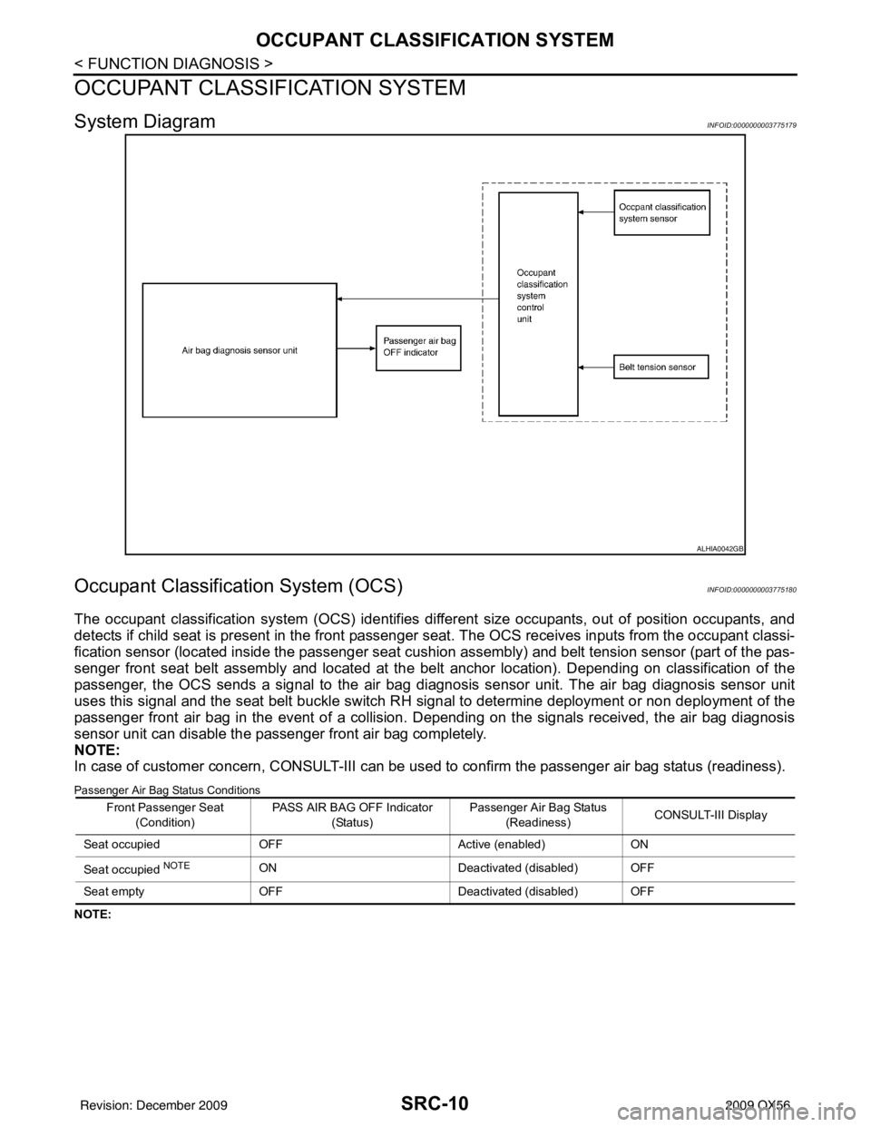
System DiagramINFOID:0000000003775179
Occupant Classification System (OCS)INFOID:0000000003775180
The occupant classification system (OCS) identifies different size occupants, out of position occupants, and
detects if child seat is present in the front passenger seat. The OCS receives inputs from the occupant classi-
fication sensor (located inside the passenger seat cushion assembly) and belt tension sensor (part of the pas-
senger front seat belt assembly and located at the belt anchor location). Depending on classification of the
passenger, the OCS sends a signal to the air bag diagnos is sensor unit. The air bag diagnosis sensor unit
uses this signal and the seat belt buckle switch RH signal to determine deployment or non deployment of the
passenger front air bag in the event of a collision. Depending on the signals received, the air bag diagnosis
sensor unit can disable the passenger front air bag completely.
NOTE:
In case of customer concern, CONSULT-III can be used to confirm the passenger air bag status (readiness).
Passenger Air Bag Status Conditions
NOTE:
ALHIA0042GB
Front Passenger Seat
(Condition) PASS AIR BAG OFF Indicator
(Status) Passenger Air Bag Status
(Readiness) CONSULT-III Display
Seat occupied OFF Active (enabled)ON
Seat occupied
NOTEON Deactivated (disabled) OFF
Seat empty OFF Deactivated (disabled) OFF
Revision: December 20092009 QX56
Page 3511 of 4171

ON BOARD DIAGNOSTIC (OBD) SYSTEMSRC-13
< FUNCTION DIAGNOSIS >
C
DE
F
G
I
J
K L
M A
B
SRC
N
O P
ON BOARD DIAGNOSTIC (OBD) SYSTEM
Trouble Diagnosis IntroductionINFOID:0000000003775184
CAUTION:
• Do not use electrical test equipment on any circui t related to the SRS unless instructed to do so in
this Service Manual. SRS wiring harnesses can be id entified by yellow and/or orange harness con-
nectors.
• Do not attempt to repair, splice or modify SRS wiring harnesses. If a harness is damaged, replace it
with a new one.
• Keep ground connections clean.
DIAGNOSIS FUNCTION
The SRS self-diagnosis results can be read by usi ng “AIR BAG” warning lamp and/or CONSULT-III.
The User mode is exclusively prepared for the customer (driver). This mode warns the driver of a system mal-
function through the operation of the “AIR BAG” warning lamp.
The Diagnosis mode allows the technician to locate and inspect the malfunctioning part.
The mode applications for the “AIR BAG” warning lamp and CONSULT-III are as follows:
HOW TO PERFORM TROUBLE DIAGNOSES FOR QUICK AND ACCURATE REPAIR
A good understanding of the malfunction conditions can make troubleshooting faster and more accurate.
In general, each customer feels differently about a malf unction. It is important to fully understand the symp-
toms or conditions for a customer complaint.
Information From Customer
WHAT - Vehicle model
WHEN - Date, Frequencies
WHERE - Road conditions
HOW - Operating conditions, Symptoms
Preliminary Check
Check that the following parts are in good order.
•Battery
•Fuse
• System component-to-harness connections
SRS Operation CheckINFOID:0000000003775185
DIAGNOSTIC PROCEDURE 1
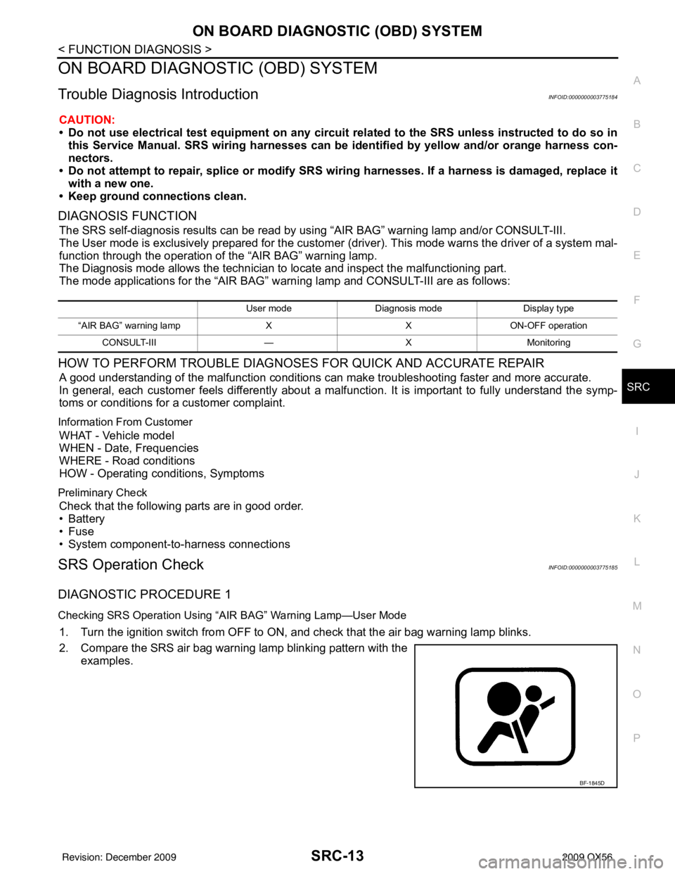
Checking SRS Operation Using “AIR BAG” Warning Lamp—User Mode
1. Turn the ignition switch from OFF to ON, and check that the air bag warning lamp blinks.
2. Compare the SRS air bag warning lamp blinking pattern with the examples.
User mode Diagnosis mode Display type
“AIR BAG” warning lamp XXON-OFF operation
CONSULT-III —XMonitoring
BF-1845D
Revision: December 20092009 QX56