2009 INFINITI QX56 drain bolt
[x] Cancel search: drain boltPage 3831 of 4171
A/T FLUID COOLERTM-183
< ON-VEHICLE MAINTENANCE >
CEF
G H
I
J
K L
M A
B
TM
N
O P
A/T FLUID COOLER
A/T Fluid Cooler CleaningINFOID:0000000004187475
Whenever an A/T is repaired, overhauled, or replaced, t he A/T fluid cooler mounted in the radiator must be
inspected and cleaned.
Metal debris and friction material, if present, can becom e trapped in the A/T fluid cooler. This debris can con-
taminate the newly serviced A/T or, in severe cases, can bl ock or restrict the flow of A/T fluid. In either case,
malfunction of the newly serviced A/T may result.
Debris, if present, may build up as A/T fluid enters the c ooler inlet. It will be necessary to back flush the cooler
through the cooler outlet in order to flush out any built up debris.
A/T FLUID COOLER CLEANING PROCEDURE
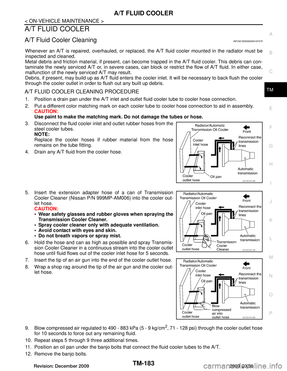
1. Position a drain pan under the A/T inlet and outle t fluid cooler tube to cooler hose connection.
2. Put a different color matching mark on each cooler tube to cooler hose connection to aid in assembly. CAUTION:
Use paint to make the matching mark. Do not damage the tubes or hose.
3. Disconnect the fluid cooler inle t and outlet rubber hoses from the
steel cooler tubes.
NOTE:
Replace the cooler hoses if rubber material from the hose
remains on the tube fitting.
4. Drain any A/T fluid from the cooler hose.
5. Insert the extension adapter hose of a can of Transmission Cooler Cleaner (Nissan P/N 999MP-AM006) into the cooler out-
let hose.
CAUTION:
Wear safety glasses and rubber gloves when spraying theTransmission Cooler Cleaner.
Spray cooler cleaner only with adequate ventilation.
Avoid contact with eyes and skin.
Do not breath vapors or spray mist.
6. Hold the hose and can as high as possible and spray Transmis- sion Cooler Cleaner in a continuous stream into the cooler outlet
hose until fluid flows out of the cooler inlet hose for 5 seconds.
7. Insert the tip of an air gun into the end of the cooler outlet hose.
8. Wrap a shop rag around the tip of the air gun and the cooler out- let hose.
9. Blow compressed air regulated to 490 - 883 kPa (5 - 9 kg/cm
2, 71 - 128 psi) through the cooler outlet hose
for 10 seconds to force out any remaining fluid.
10. Repeat steps 5 through 9 three additional times.
11. Position an oil pan under the banjo bolts that connect the fluid cooler tubes to the A/T.
12. Remove the banjo bolts.
SCIA3830E
SCIA3831E
SCIA3832E
Revision: December 20092009 QX56
Page 3832 of 4171
TM-184
< ON-VEHICLE MAINTENANCE >
A/T FLUID COOLER
13. Flush each steel line from the cooler side back toward the A/T by spraying Transmission Cooler Cleanerin a continuous stream for 5 seconds.
14. Blow compressed air regulated to 490 - 883 kPa (5 - 9 kg/cm
2, 71 - 128 psi) through each steel line from
the cooler side back toward the A/T for 10 seconds to force out any remaining fluid.
15. Ensure all debris is removed from the steel cooler lines.
16. Ensure all debris is removed from the banjo bolts and fittings.
17. Perform A/T fluid cooler diagnosis procedure.
A/T FLUID COOLER DIAGNOSIS PROCEDURE
NOTE:
Insufficient cleaning of the cooler inlet hose exte rior may lead to inaccurate debris identification.
1. Position a drain pan under the A/T inlet and outlet fluid cooler tube to cooler hose connection.
2. Clean the exterior and tip of the cooler inlet hose.
3. Put a different color matching mark on each cooler tube to cooler hose connection to aid in assembly. CAUTION:
Use paint to make the matching mark. Do not damage the tubes or hose.
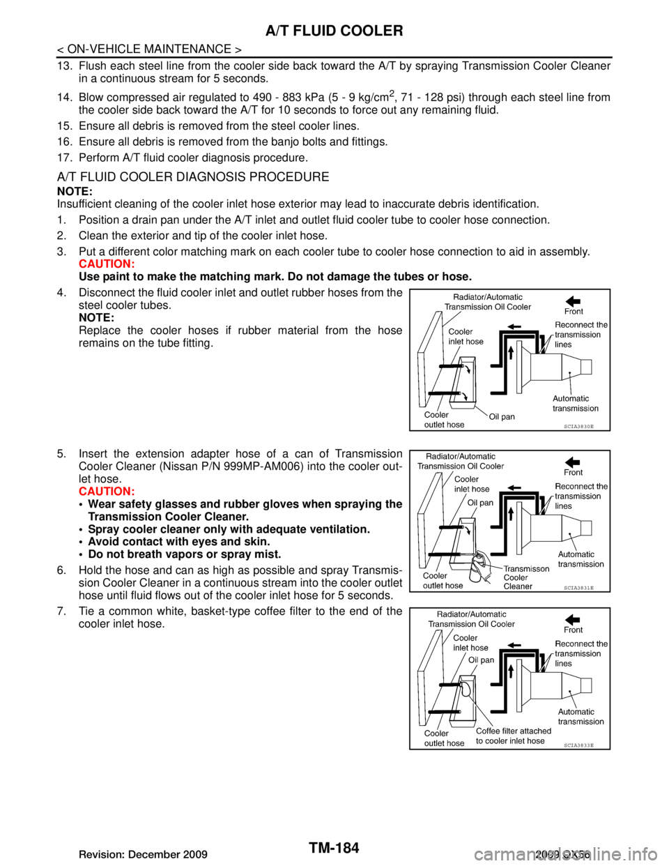
4. Disconnect the fluid cooler inle t and outlet rubber hoses from the
steel cooler tubes.
NOTE:
Replace the cooler hoses if rubber material from the hose
remains on the tube fitting.
5. Insert the extension adapter hose of a can of Transmission
Cooler Cleaner (Nissan P/N 999MP-AM006) into the cooler out-
let hose.
CAUTION:
Wear safety glasses and rubber gloves when spraying the
Transmission Cooler Cleaner.
Spray cooler cleaner only wi th adequate ventilation.
Avoid contact with eyes and skin.
Do not breath vapors or spray mist.
6. Hold the hose and can as high as possible and spray Transmis- sion Cooler Cleaner in a continuous stream into the cooler outlet
hose until fluid flows out of the cooler inlet hose for 5 seconds.
7. Tie a common white, basket-type coffee filter to the end of the cooler inlet hose.
SCIA3830E
SCIA3831E
SCIA3833E
Revision: December 20092009 QX56
Page 3849 of 4171
OIL PANTM-201
< ON-VEHICLE REPAIR >
CEF
G H
I
J
K L
M A
B
TM
N
O P
OIL PAN
Oil PanINFOID:0000000005880214
REMOVAL AND INSTALLATION
Removal
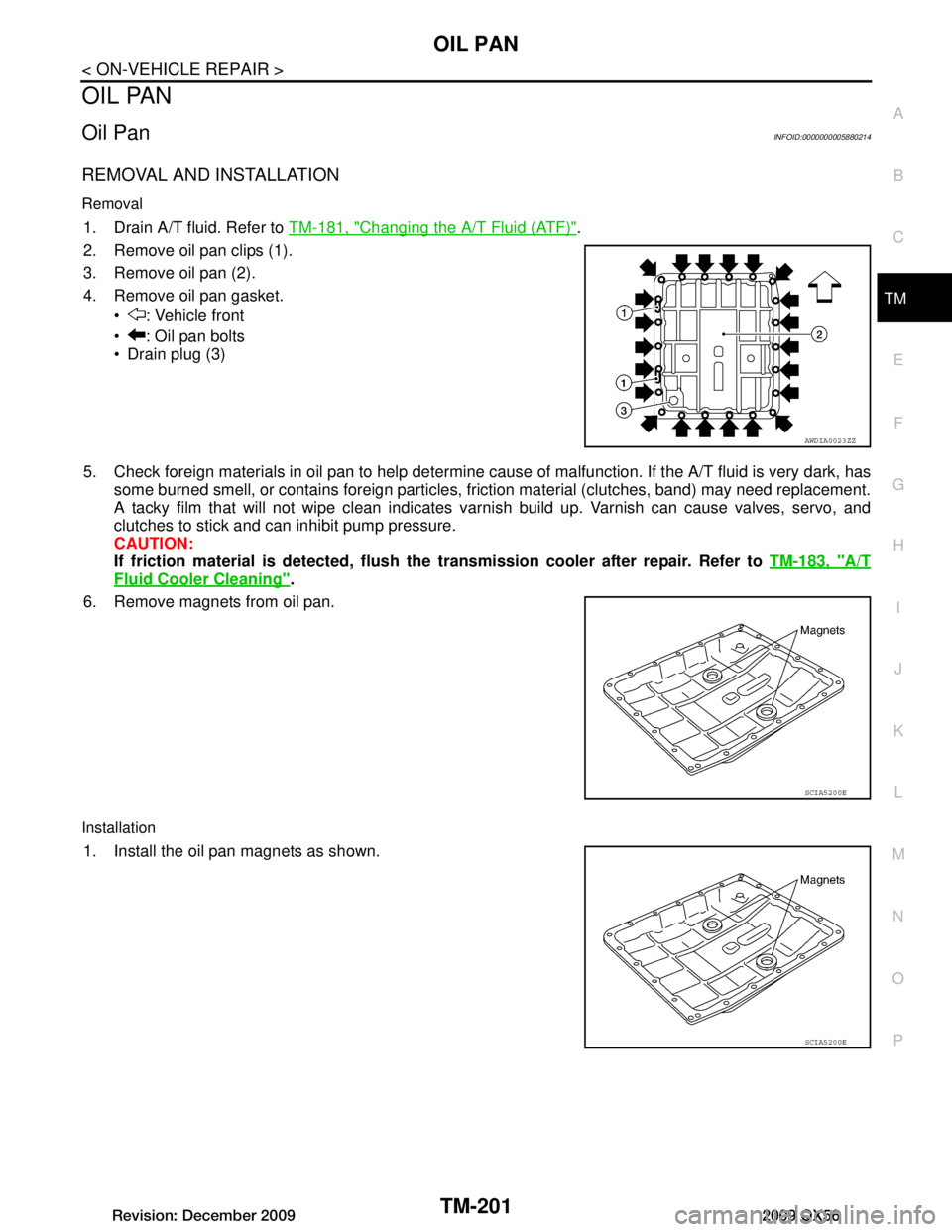
1. Drain A/T fluid. Refer to TM-181, "Changing the A/T Fluid (ATF)".
2. Remove oil pan clips (1).
3. Remove oil pan (2).
4. Remove oil pan gasket. : Vehicle front
: Oil pan bolts
Drain plug (3)
5. Check foreign materials in oil pan to help determine c ause of malfunction. If the A/T fluid is very dark, has
some burned smell, or contains foreign particles, friction material (clutches, band) may need replacement.
A tacky film that will not wipe clean indicates varnis h build up. Varnish can cause valves, servo, and
clutches to stick and can inhibit pump pressure.
CAUTION:
If friction material is detected, flush th e transmission cooler after repair. Refer to TM-183, "A/T
Fluid Cooler Cleaning".
6. Remove magnets from oil pan.
Installation
1. Install the oil pan magnets as shown.
AWDIA0023ZZ
SCIA5200E
SCIA5200E
Revision: December 20092009 QX56
Page 3850 of 4171
TM-202
< ON-VEHICLE REPAIR >
OIL PAN
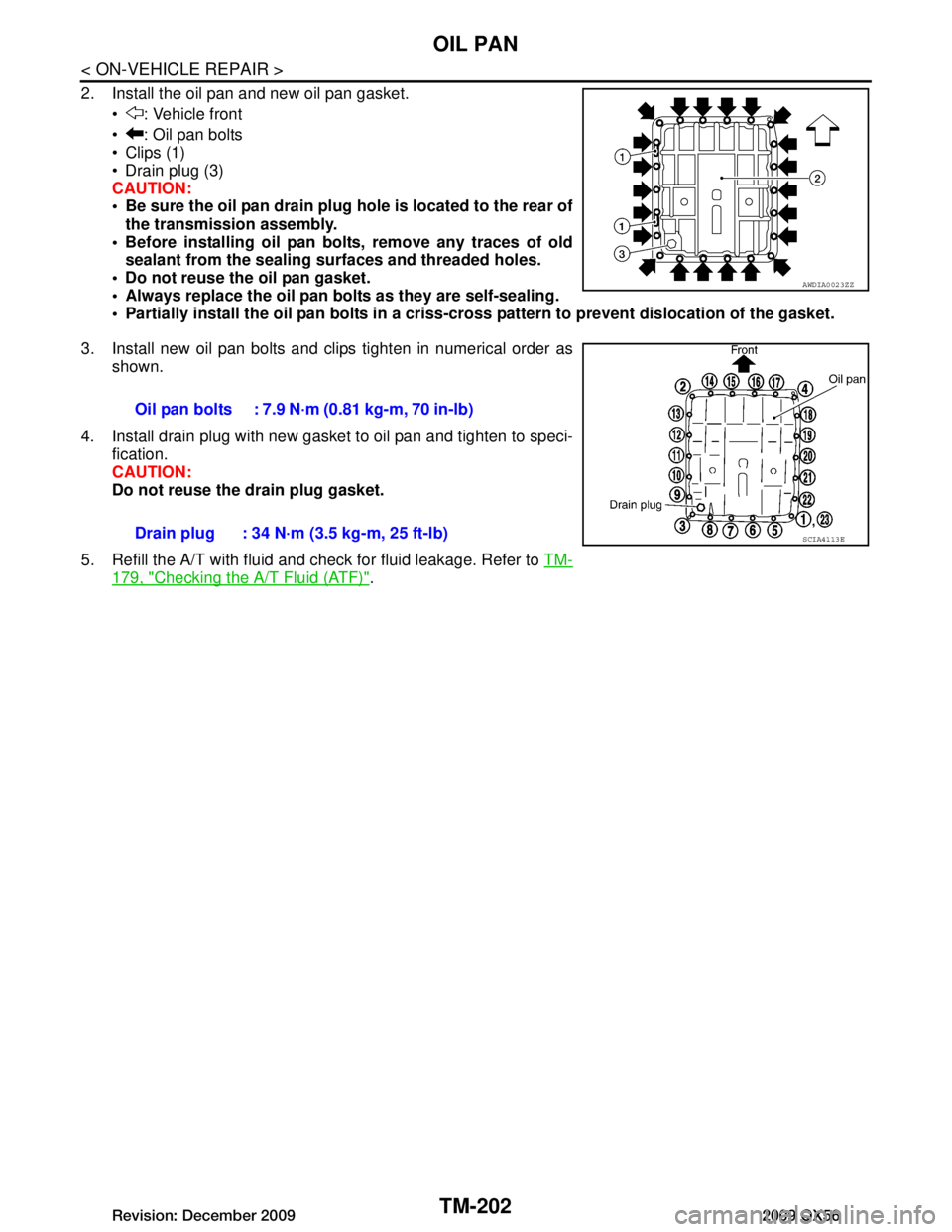
2. Install the oil pan and new oil pan gasket. : Vehicle front
: Oil pan bolts
Clips (1)
Drain plug (3)
CAUTION:
Be sure the oil pan drain plug hole is located to the rear ofthe transmission assembly.
Before installing oil pan bolts, remove any traces of old sealant from the sealing su rfaces and threaded holes.
Do not reuse the oil pan gasket.
Always replace the oil pan bolts as they are self-sealing.
Partially install the oil pan bolts in a criss- cross pattern to prevent dislocation of the gasket.
3. Install new oil pan bolts and clips tighten in numerical order as shown.
4. Install drain plug with new gasket to oil pan and tighten to speci- fication.
CAUTION:
Do not reuse the drain plug gasket.
5. Refill the A/T with fluid and check for fluid leakage. Refer to TM-
179, "Checking the A/T Fluid (ATF)".
AWDIA0023ZZ
Oil pan bolts : 7.9 N·m (0.81 kg-m, 70 in-lb)
Drain plug : 34 N·m (3.5 kg-m, 25 ft-lb)
SCIA4113E
Revision: December 20092009 QX56
Page 3851 of 4171
CONTROL VALVE WITH TCMTM-203
< ON-VEHICLE REPAIR >
CEF
G H
I
J
K L
M A
B
TM
N
O P
CONTROL VALVE WITH TCM
Control Valve with TCM and A/T Fluid Temperature Sensor 2INFOID:0000000004219688
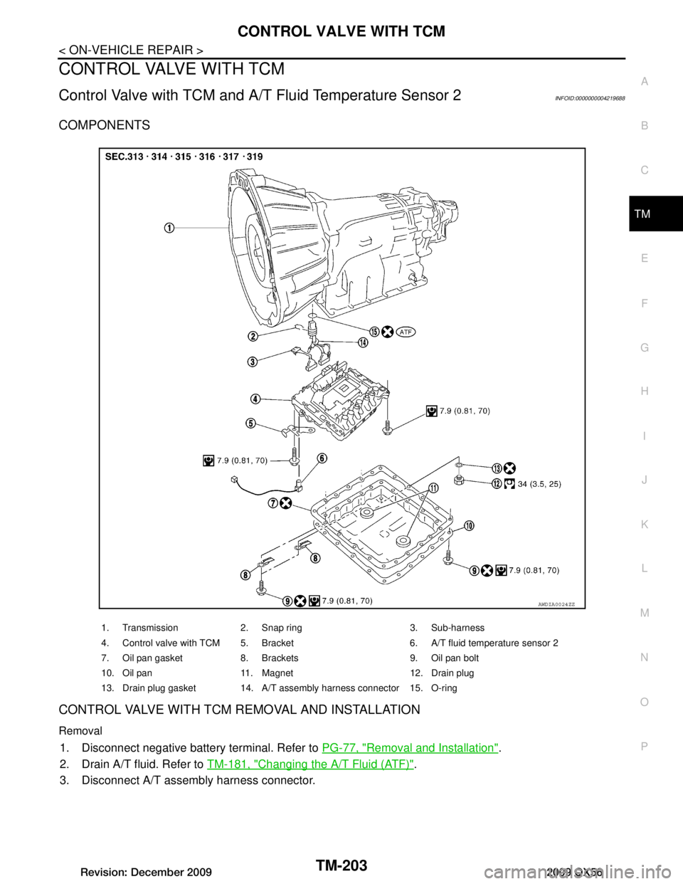
COMPONENTS
CONTROL VALVE WITH TCM REMOVAL AND INSTALLATION
Removal
1. Disconnect negative battery terminal. Refer to PG-77, "Removal and Installation".
2. Drain A/T fluid. Refer to TM-181, "Changing the A/T Fluid (ATF)"
.
3. Disconnect A/T assembly harness connector.
1. Transmission 2. Snap ring 3. Sub-harness
4. Control valve with TCM 5. Bracket 6. A/T fluid temperature sensor 2
7. Oil pan gasket 8. Brackets 9. Oil pan bolt
10. Oil pan 11. Magnet 12. Drain plug
13. Drain plug gasket 14. A/T assembly harness connector 15. O-ring
AWDIA0024ZZ
Revision: December 20092009 QX56
Page 3863 of 4171
TRANSMISSION ASSEMBLYTM-215
< REMOVAL AND INSTALLATION >
CEF
G H
I
J
K L
M A
B
TM
N
O P
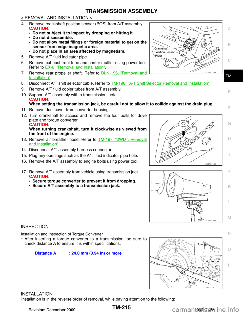
4. Remove crankshaft position sensor (POS) from A/T assembly. CAUTION:
Do not subject it to impact by dropping or hitting it.
Do not disassemble.
Do not allow metal filings or foreign material to get on the
sensor front edge magnetic area.
Do not place in an area affected by magnetism.
5. Remove A/T fluid indicator pipe.
6. Remove exhaust front tube and center muffler using power tool. Refer to EX-6, "Removal and Installation"
.
7. Remove rear propeller shaft. Refer to DLN-196, "Removal and
Installation".
8. Disconnect A/T shift selector cable. Refer to TM-196, "A/T Shift Selector Removal and Installation"
.
9. Remove A/T fluid cooler tubes from A/T assembly.
10. Support A/T assembly with a transmission jack. CAUTION:
When setting the transmission jack, be careful not to allow it to collide against the drain plug.
11. Remove dust cover from converter housing.
12. Turn crankshaft to access and remove the four bolts for drive plate and torque converter.
CAUTION:
When turning crankshaft, turn it clockwise as viewed from
the front of the engine.
13. Remove air breather hose. Refer to TM-197, "2WD : Removal
and Installation".
14. Disconnect A/T assembly harness connector.
15. Plug any openings such as the A/T fluid indicator pipe hole.
16. Remove the A/T assembly to engine bolts using power tool.
17. Remove A/T assembly from vehicle using transmission jack. CAUTION:
Secure torque converter to prevent it from dropping.
Secure A/T assembly to a transmission jack.
INSPECTION
Installation and Inspection of Torque Converter
After inserting a torque converter to a transmission, be sure to check distance A to ensure it is within specifications.
INSTALLATION
Installation is in the reverse order of removal, while paying attention to the following:
LCIA0334E
LCIA0335E
SCIA0499E
Distance A : 24.0 mm (0.94 in) or more
SAT017B
Revision: December 20092009 QX56
Page 3866 of 4171
TM-218
< REMOVAL AND INSTALLATION >
TRANSMISSION ASSEMBLY
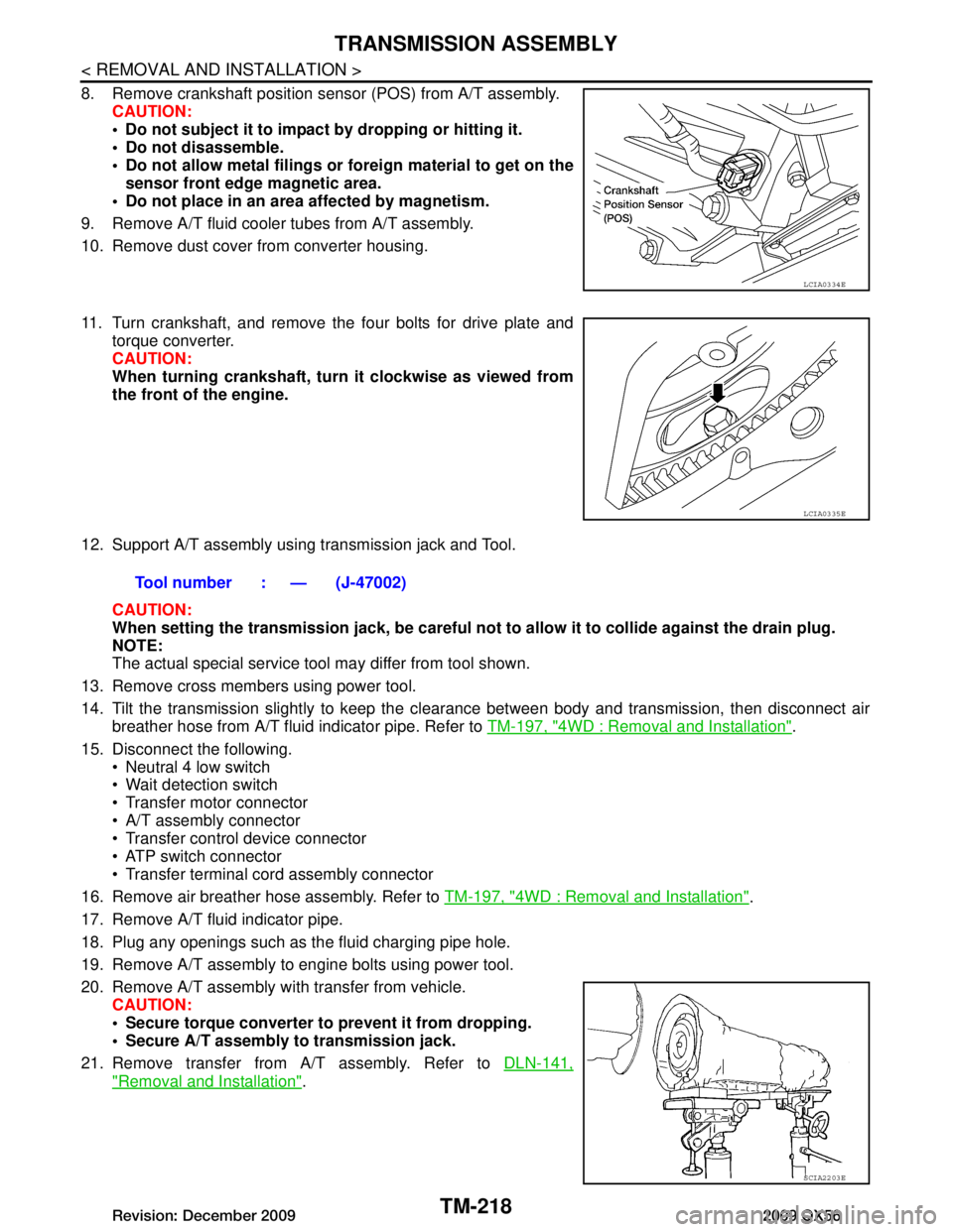
8. Remove crankshaft position sensor (POS) from A/T assembly.CAUTION:
Do not subject it to impact by dropping or hitting it.
Do not disassemble.
Do not allow metal filings or fo reign material to get on the
sensor front edge magnetic area.
Do not place in an area affected by magnetism.
9. Remove A/T fluid cooler tubes from A/T assembly.
10. Remove dust cover from converter housing.
11. Turn crankshaft, and remove the four bolts for drive plate and torque converter.
CAUTION:
When turning crankshaft, turn it clockwise as viewed from
the front of the engine.
12. Support A/T assembly using transmission jack and Tool. CAUTION:
When setting the transmission jack, be careful not to allow it to collide against the drain plug.
NOTE:
The actual special service tool may differ from tool shown.
13. Remove cross members using power tool.
14. Tilt the transmission slightly to keep the cl earance between body and transmission, then disconnect air
breather hose from A/T fluid indicator pipe. Refer to TM-197, "4WD : Removal and Installation"
.
15. Disconnect the following. Neutral 4 low switch
Wait detection switch
Transfer motor connector
A/T assembly connector
Transfer control device connector
ATP switch connector
Transfer terminal cord assembly connector
16. Remove air breather hose assembly. Refer to TM-197, "4WD : Removal and Installation"
.
17. Remove A/T fluid indicator pipe.
18. Plug any openings such as the fluid charging pipe hole.
19. Remove A/T assembly to engine bolts using power tool.
20. Remove A/T assembly with transfer from vehicle. CAUTION:
Secure torque converter to prevent it from dropping.
Secure A/T assembly to transmission jack.
21. Remove transfer from A/T assembly. Refer to DLN-141,
"Removal and Installation".
LCIA0334E
LCIA0335E
Tool number : — (J-47002)
SCIA2203E
Revision: December 20092009 QX56
Page 3874 of 4171

TM-226
< DISASSEMBLY AND ASSEMBLY >
OVERHAUL
19. Parking rod 20. Manual shaft oil seal 21. Manual shaft
22. O-ring 23. Band servo anchor end pin 24. Detent spring
25. Spacer 26. Seal rings 27. Return spring
28. O-ring 29. Servo assembly 30. Snap ring
31. Snap ring 32. Sub-harness 33. Control valve with TCM
34. Bracket 35. A/T fluid temperature sensor 2 36. Oil pan
37. Magnets 38. Drain plug 39. Drain plug gasket
40. Oil pan bolt 41. Oil pan gasket 42. A/T assembly harness connector
43. O-ring 44. Retaining pin 45. Transmission case
Revision: December 20092009 QX56