2009 INFINITI QX56 drain bolt
[x] Cancel search: drain boltPage 1859 of 4171
EM-36
< ON-VEHICLE REPAIR >
OIL PAN AND OIL STRAINER
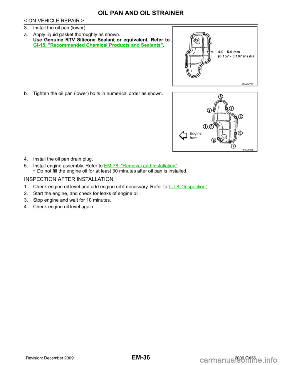
3. Install the oil pan (lower).
a. Apply liquid gasket thoroughly as shown.Use Genuine RTV Silicone Sealant or equivalent. Refer to
GI-15, "
Recommended Chemical Products and Sealants".
b. Tighten the oil pan (lower) bolts in numerical order as shown.
4. Install the oil pan drain plug.
5. Install engine assembly. Refer to EM-78, "
Removal and Installation".
• Do not fill the engine oil for at least 30 minutes after oil pan is installed.
INSPECTION AFTER INSTALLATION
1. Check engine oil level and add engine oil if necessary. Refer to LU-8, "Inspection".
2. Start the engine, and check for leaks of engine oil.
3. Stop engine and wait for 10 minutes.
4. Check engine oil level again.
KBIA2471E
PBIC2595E
Revision: December 20092009 QX56
Page 1902 of 4171
ENGINE ASSEMBLYEM-79
< REMOVAL AND INSTALLATION >
C
DE
F
G H
I
J
K L
M A
EM
NP
O
1. Release the fuel pressure. Refer to
EC-487, "Fuel Pressure Check".
2. Drain the engine coolant. Refer to CO-11, "
Changing Engine Coolant".
3. Drain the engine oil. Refer to LU-9, "
Changing Engine Oil".
4. Disconnect the battery negative and positive terminal. Refer to PG-76, "
Removal and Installation".
5. Remove the engine hood. Refer to DLK-230, "
Removal and Installation of Hood Assembly".
6. Remove the cowl extension. Refer to EXT-18, "
Removal and Installation".
7. Remove the air duct and air cleaner case assembly. Refer to EM-25, "
Removal and Installation".
8. Remove the radiator assembly and hoses. Refer to CO-15, "
Removal and Installation".
NOTE:
To prevent possible A/T fluid drain from transmissi on opening, use appropriate cap to close off transmis-
sion opening during operation.
9. Remove the drive belt. Refer to EM-13, "
Removal and Installation".
10. Remove the fan blade. Refer to CO-18, "
Removal and Installation (Crankshaft Driven Type)".
11. Disconnect the engine room harness from the fuse box and set it aside.
12. Disconnect the ECM.
13. Disconnect the engine room harness from the engine side and set it aside.
14. Disconnect the engine harness grounds.
15. Disconnect the power steering reservoir t ank from the engine and move it aside.
16. Disconnect the power steering oil pump from the engine. Move it aside and secure it using suitable wire or rope. Refer to ST-26, "
Removal and Installation"
17. Remove the A/C compressor bolts and set the compressor aside. Refer to HA-31, "Removal and Installa-
tion for Compressor" (ATC).
18. Disconnect the brake booster vacuum hose.
19. Disconnect the EVAP line.
20. Disconnect the fuel hose at the engine side connection. Refer to EM-40, "
Removal and Installation".
21. Disconnect the heater hoses at the cowl, and in stall plugs to avoid leakage of engine coolant.
22. Remove the A/T oil level indicator and indicator tube upper bolts.
23. Remove the front final drive assembly (4WD only). Refer to DLN-215, "
Removal and Installation".
24. Remove the exhaust manifolds. Refer to EM-30, "
Removal and Installation".
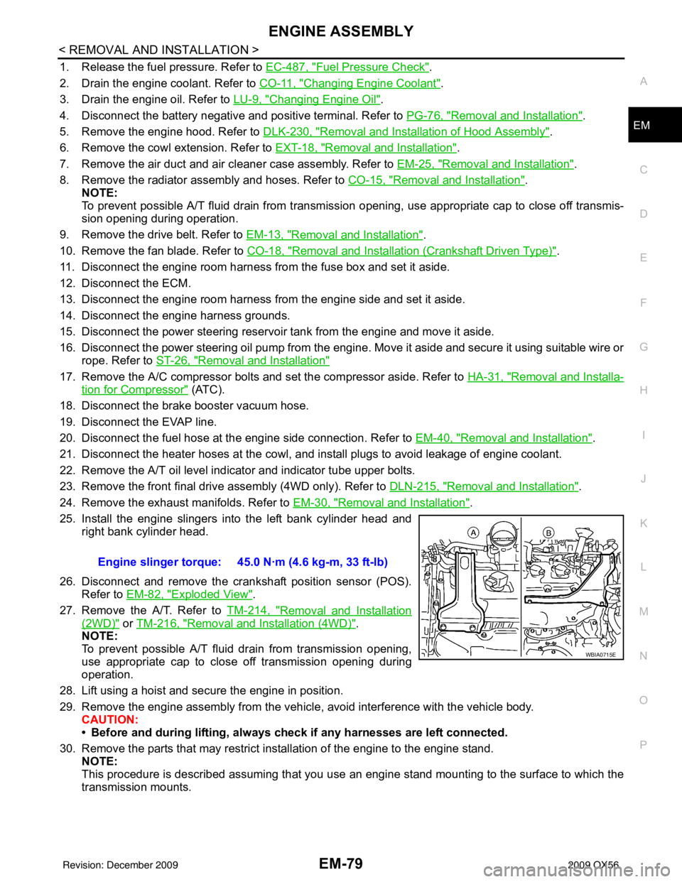
25. Install the engine slingers into the left bank cylinder head and right bank cylinder head.
26. Disconnect and remove the crankshaft position sensor (POS). Refer to EM-82, "
Exploded View".
27. Remove the A/T. Refer to TM-214, "
Removal and Installation
(2WD)" or TM-216, "Removal and Installation (4WD)".
NOTE:
To prevent possible A/T fluid drain from transmission opening,
use appropriate cap to close off transmission opening during
operation.
28. Lift using a hoist and secure the engine in position.
29. Remove the engine assembly from the vehicl e, avoid interference with the vehicle body.
CAUTION:
• Before and during lifting, always check if any harnesses are left connected.
30. Remove the parts that may restrict installation of the engine to the engine stand. NOTE:
This procedure is described assuming that you use an engine stand mounting to the surface to which the
transmission mounts. Engine slinger torque: 45.0 N·m (4.6 kg-m, 33 ft-lb)
WBIA0715E
Revision: December 20092009 QX56
Page 1906 of 4171
ENGINE UNITEM-83
< DISASSEMBLY AND ASSEMBLY >
C
DE
F
G H
I
J
K L
M A
EM
NP
O
Disassembly and AssemblyINFOID:0000000005885902
DISASSEMBLY
NOTE:
Explained here is how to disassemble with engine stand supporting transmission surface. When using differ-
ent type of engine stand, some steps may be different.
1. Remove engine assembly and mount to engine stand. Refer to
EM-78, "
Removal and Installation".
CAUTION:
Before removing the hanging chains, make sure engi ne stand is stable and there is no risk of over-
turning.
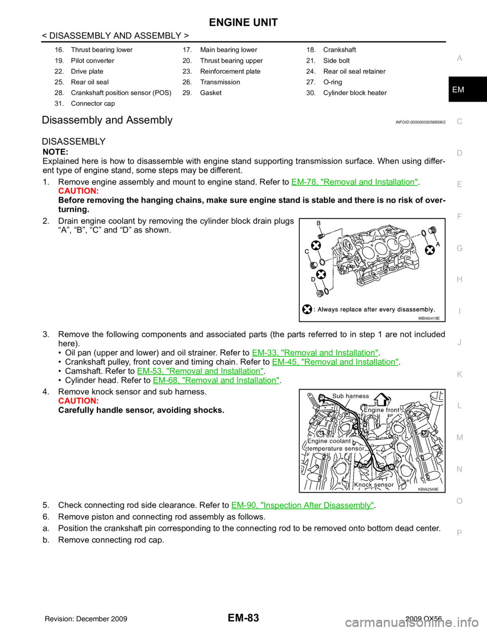
2. Drain engine coolant by removing the cylinder block drain plugs “A”, “B”, “C” and “D” as shown.
3. Remove the following components and associated parts (the parts referred to in step 1 are not included here).
• Oil pan (upper and lower) and oil strainer. Refer to EM-33, "
Removal and Installation".
• Crankshaft pulley, front cover and timing chain. Refer to EM-45, "
Removal and Installation".
• Camshaft. Refer to EM-53, "
Removal and Installation".
• Cylinder head. Refer to EM-68, "
Removal and Installation".
4. Remove knock sensor and sub harness. CAUTION:
Carefully handle sensor, avoiding shocks.
5. Check connecting rod side clearance. Refer to EM-90, "
Inspection After Disassembly".
6. Remove piston and connecting rod assembly as follows.
a. Position the crankshaft pin corresponding to the connecting rod to be removed onto bottom dead center.
b. Remove connecting rod cap.
16. Thrust bearing lower 17. Main bearing lower18. Crankshaft
19. Pilot converter 20. Thrust bearing upper21. Side bolt
22. Drive plate 23. Reinforcement plate24. Rear oil seal retainer
25. Rear oil seal 26. Transmission27. O-ring
28. Crankshaft position sensor (POS) 29. Gasket 30. Cylinder block heater
31. Connector cap
WBIA0419E
KBIA2549E
Revision: December 20092009 QX56
Page 2184 of 4171
FSU-14
< REMOVAL AND INSTALLATION >
COIL SPRING AND SHOCK ABSORBER
REMOVAL AND INSTALLATION
COIL SPRING AND SHOCK ABSORBER
Removal and InstallationINFOID:0000000003772274
REMOVAL
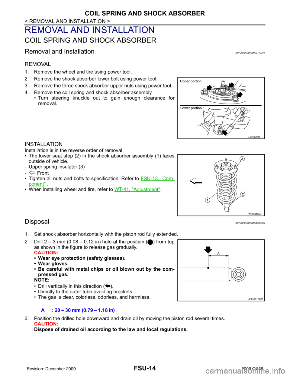
1. Remove the wheel and tire using power tool.
2. Remove the shock absorber lower bolt using power tool.
3. Remove the three shock absorber upper nuts using power tool.
4. Remove the coil spring and shock absorber assembly.• Turn steering knuckle out to gain enough clearance forremoval.
INSTALLATION
Installation is in the reverse order of removal.
• The lower seat step (2) in the shock absorber assembly (1) faces
outside of vehicle.
- Upper spring insulator (3)
- : Front
• Tighten all nuts and bolts to specification. Refer to FSU-13, "
Com-
ponent" .
• When installing wheel and tire, refer to WT-41, "
Adjustment".
DisposalINFOID:0000000005867502
1. Set shock absorber horizontally with the piston rod fully extended.
2. Drill 2 – 3 mm (0.08 – 0.12 in) hole at the position ( ) from top
as shown in the figure to release gas gradually.
CAUTION:
• Wear eye protection (safety glasses).
• Wear gloves.
• Be careful with metal chips or oil blown out by the com-pressed gas.
NOTE:
• Drill vertically in this direction ( ).
• Directly to the outer tube avoiding brackets.
• The gas is clear, colorless, odorless, and harmless.
3. Position the drilled hole downward and drain oil by moving the piston rod several times. CAUTION:
Dispose of drained oil according to the law and local regulations.
LEIA0093E
WEIA0155E
A : 20 – 30 mm (0.79 – 1.18 in)
JPEIA0161ZZ
Revision: December 20092009 QX56
Page 2294 of 4171
HA-30
< ON-VEHICLE REPAIR >
REFRIGERATION SYSTEM
Rear A/C System
NOTE:
Refer to HA-5, "Precaution for Refrigerant Connection"
.
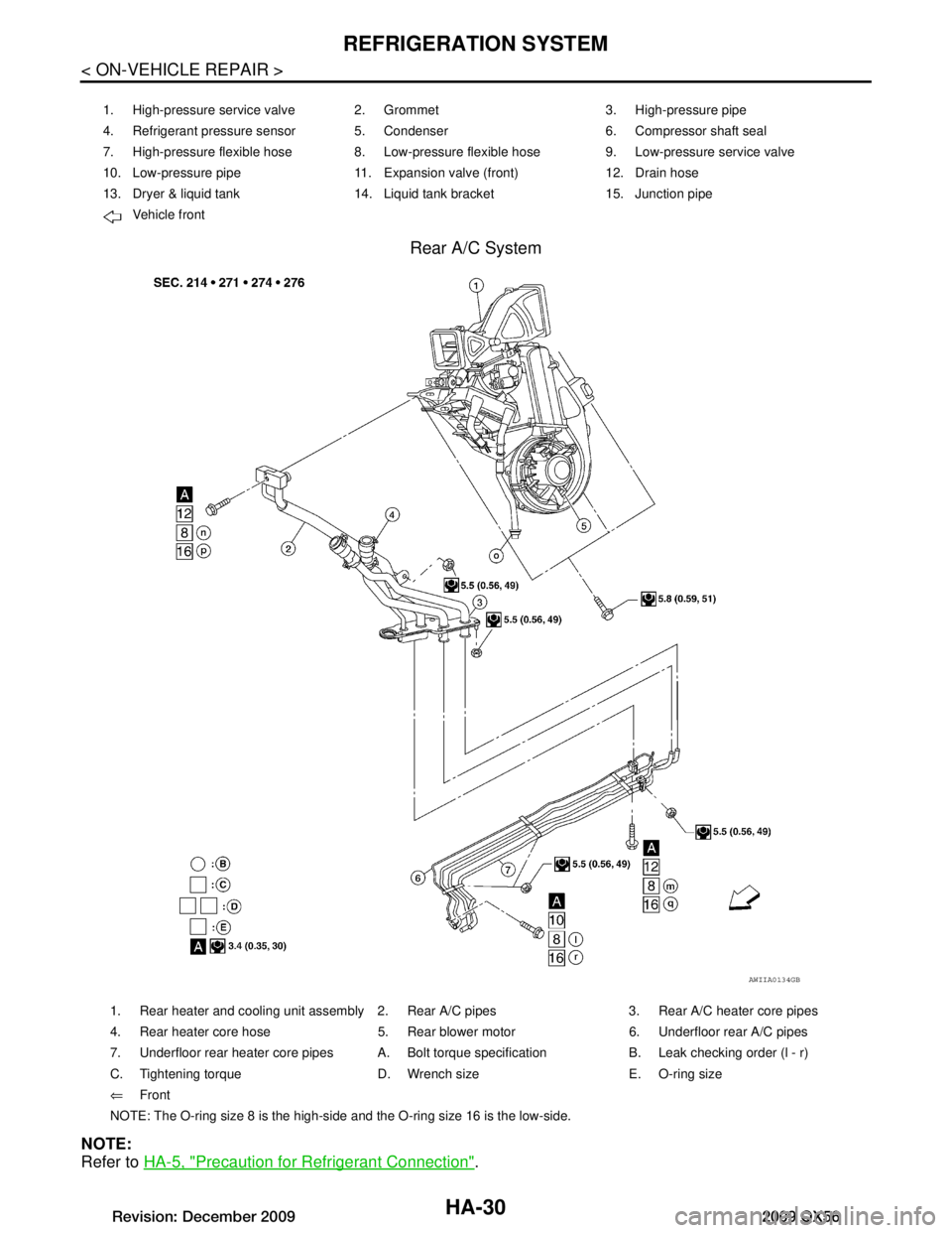
1. High-pressure service valve 2. Grommet 3. High-pressure pipe
4. Refrigerant pressure sensor 5. Condenser 6. Compressor shaft seal
7. High-pressure flexible hose 8. Low-pressure flexible hose 9. Low-pressure service valve
10. Low-pressure pipe 11. Expansion valve (front) 12. Drain hose
13. Dryer & liquid tank 14. Liquid tank bracket 15. Junction pipe
Vehicle front
AWIIA0134GB
1. Rear heater and cooling unit assembly 2. Rear A/C pipes 3. Rear A/C heater core pipes
4. Rear heater core hose 5. Rear blower motor 6. Underfloor rear A/C pipes
7. Underfloor rear heater core pipes A. Bolt torque specification B. Leak checking order (l - r)
C. Tightening torque D. Wrench size E. O-ring size
⇐Front
NOTE: The O-ring size 8 is the high-side and the O-ring size 16 is the low-side.
Revision: December 20092009 QX56
Page 2301 of 4171
LOW-PRESSURE PIPEHA-37
< ON-VEHICLE REPAIR >
C
DE
F
G H
J
K L
M A
B
HA
N
O P
LOW-PRESSURE PIPE
Removal and Installation for Low-Pressure PipeINFOID:0000000003775312
REMOVAL
1. Discharge the refrigerant. Refer to HA-20, "HFC-134a (R-134a) Service Procedure".
2. Remove the cowl top and the cowl top extension. Refer to EXT-18, "Removal and Installation"
.
3. Remove the low-pressure pipe. CAUTION:
Cap or wrap the joint of the pipes with suitable material such as viny l tape to avoid the entry of air.
INSTALLATION
Installation is in the reverse order of removal.
Refer to HA-29, "Component"
.
CAUTION:
Replace the O-ring of the high/low-pressure pipe with a new one, then apply compressor oil to it
when installing it.
After charging refrigerant, check for leaks.
Removal and Installation for Rear High- and Low-Pressure A/C and Heater Core Pipes
INFOID:0000000003775313
REMOVAL
1. Discharge the refrigerant from the A/C system. Refer to HA-20, "HFC-134a (R-134a) Service Procedure".
2. Drain the coolant from the engine cooling system. Refer to CO-11, "Changing Engine Coolant"
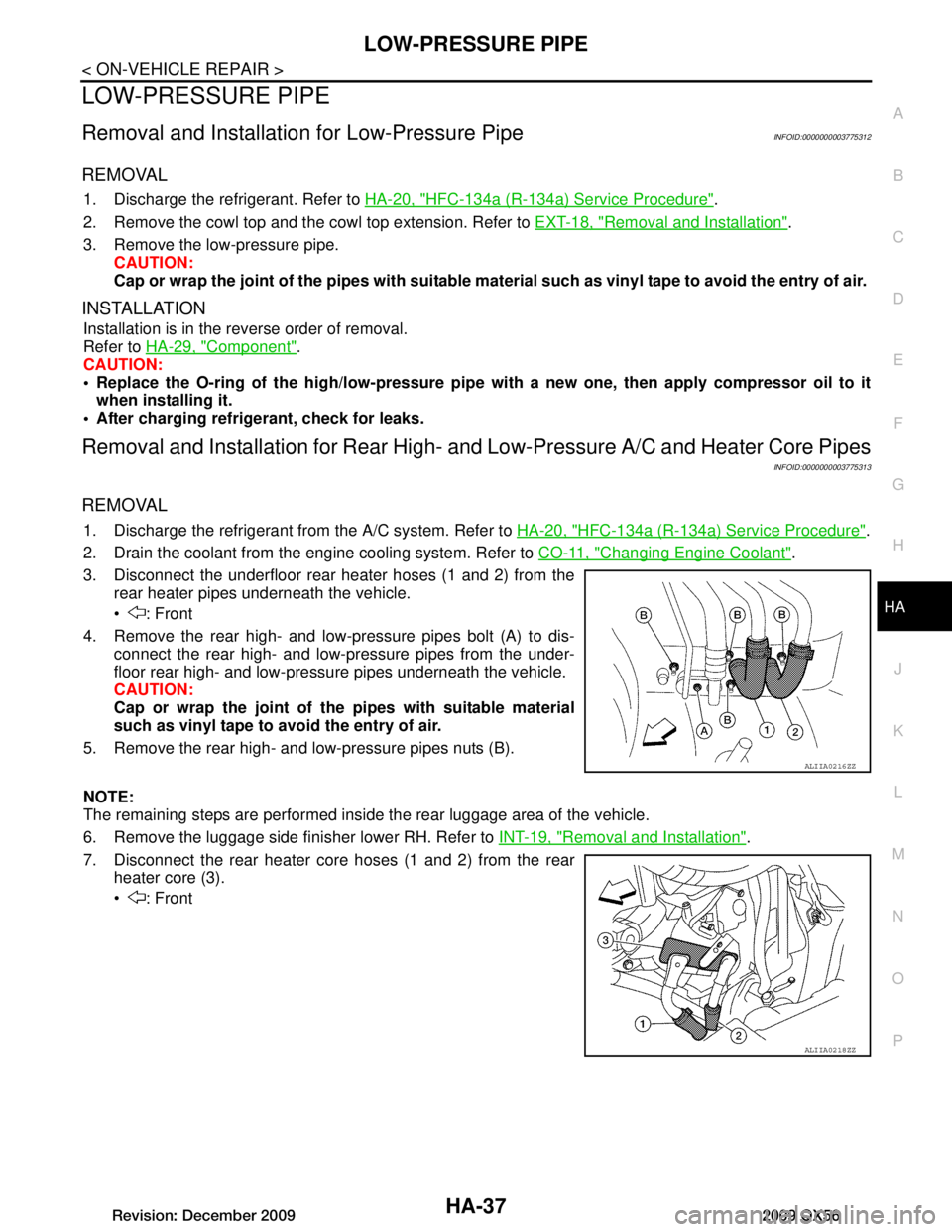
.
3. Disconnect the underfloor rear heater hoses (1 and 2) from the rear heater pipes underneath the vehicle.
: Front
4. Remove the rear high- and low-pressure pipes bolt (A) to dis- connect the rear high- and low-pressure pipes from the under-
floor rear high- and low-pressu re pipes underneath the vehicle.
CAUTION:
Cap or wrap the joint of the pipes with suitable material
such as vinyl tape to avoid the entry of air.
5. Remove the rear high- and low-pressure pipes nuts (B).
NOTE:
The remaining steps are performed inside the rear luggage area of the vehicle.
6. Remove the luggage side finisher lower RH. Refer to INT-19, "Removal and Installation"
.
7. Disconnect the rear heater core hoses (1 and 2) from the rear heater core (3).
: Front
ALIIA0216ZZ
ALIIA0218ZZ
Revision: December 20092009 QX56
Page 2302 of 4171
HA-38
< ON-VEHICLE REPAIR >
LOW-PRESSURE PIPE
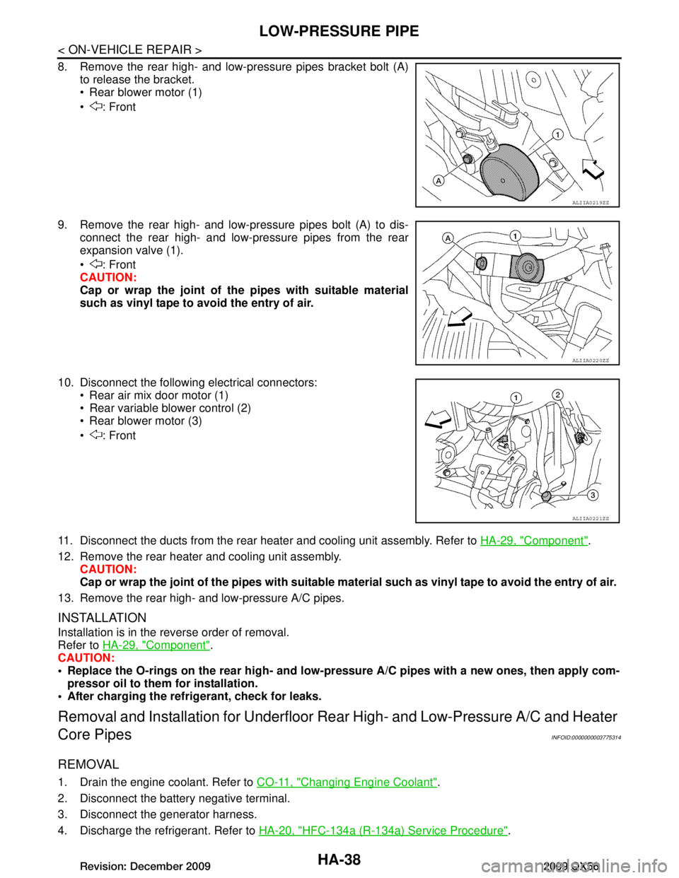
8. Remove the rear high- and low-pressure pipes bracket bolt (A)to release the bracket.
Rear blower motor (1)
: Front
9. Remove the rear high- and low-pressure pipes bolt (A) to dis- connect the rear high- and low-pressure pipes from the rear
expansion valve (1).
: Front
CAUTION:
Cap or wrap the joint of the pipes with suitable material
such as vinyl tape to avoid the entry of air.
10. Disconnect the following electrical connectors: Rear air mix door motor (1)
Rear variable blower control (2)
Rear blower motor (3)
: Front
11. Disconnect the ducts from the rear heater and cooling unit assembly. Refer to HA-29, "Component"
.
12. Remove the rear heater and cooling unit assembly. CAUTION:
Cap or wrap the joint of the pipes with suitable material such as viny l tape to avoid the entry of air.
13. Remove the rear high- and low-pressure A/C pipes.
INSTALLATION
Installation is in the reverse order of removal.
Refer to HA-29, "Component"
.
CAUTION:
Replace the O-rings on the rear high- and low-pr essure A/C pipes with a new ones, then apply com-
pressor oil to them for installation.
After charging the refrigerant, check for leaks.
Removal and Installation for Underfloor Rear High- and Lo w-Pressure A/C and Heater
Core Pipes
INFOID:0000000003775314
REMOVAL
1. Drain the engine coolant. Refer to CO-11, "Changing Engine Coolant".
2. Disconnect the battery negative terminal.
3. Disconnect the generator harness.
4. Discharge the refrigerant. Refer to HA-20, "HFC-134a (R-134a) Service Procedure"
.
ALIIA0219ZZ
ALIIA0220ZZ
ALIIA0221ZZ
Revision: December 20092009 QX56
Page 2305 of 4171
HIGH-PRESSURE PIPEHA-41
< ON-VEHICLE REPAIR >
C
DE
F
G H
J
K L
M A
B
HA
N
O P
HIGH-PRESSURE PIPE
Removal and Installation for High-Pressure PipeINFOID:0000000003775316
REMOVAL
1. Remove the cowl top extension. Refer to EXT-18, "Removal and Installation".
2. Disconnect the battery negative termi nal and positive battery terminal.
3. Reposition the IPDM E/R aside.
4. Remove the front left wheel and tire assembly. Refer to MA-29, "Rotation"
.
5. Position aside the front floor insulator.
6. Discharge the refrigerant. Refer to HA-20, "HFC-134a (R-134a) Service Procedure"
.
7. Remove the low pressure pipe. Refer to HA-37, "Removal and Installation for Low-Pressure Pipe"
.
8. Remove the high-pressure pipe. CAUTION:
Cap or wrap the joint of the pipe with suitable mate rial such as vinyl tape to avoid the entry of air.
INSTALLATION
Installation is in the reverse order of removal.
Refer to HA-29, "Component"
.
CAUTION:
Replace the O-ring of the high-pressure pipe with a new one, then apply compressor oil to it when
installing it.
After charging refrigerant, check for leaks.
Removal and Installation for Rear High- and Low-Pressure A/C and Heater Core Pipes
INFOID:0000000003775317
REMOVAL
1. Discharge the refrigerant from the A/C system. Refer to HA-20, "HFC-134a (R-134a) Service Procedure".
2. Drain the coolant from the engine cooling system. Refer to CO-11, "Changing Engine Coolant"
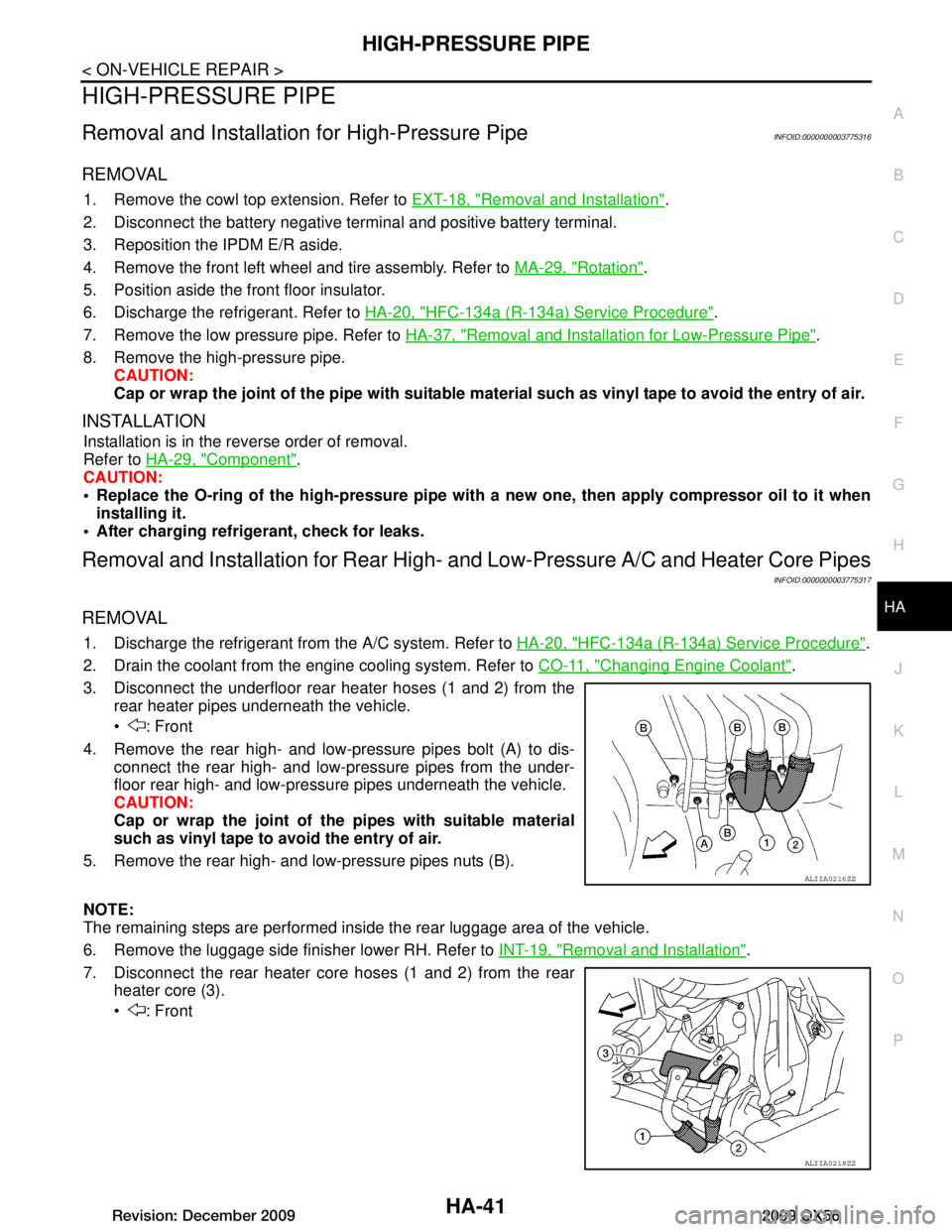
.
3. Disconnect the underfloor rear heater hoses (1 and 2) from the rear heater pipes underneath the vehicle.
: Front
4. Remove the rear high- and low-pressure pipes bolt (A) to dis- connect the rear high- and low-pressure pipes from the under-
floor rear high- and low-pressu re pipes underneath the vehicle.
CAUTION:
Cap or wrap the joint of the pipes with suitable material
such as vinyl tape to avoid the entry of air.
5. Remove the rear high- and low-pressure pipes nuts (B).
NOTE:
The remaining steps are performed inside the rear luggage area of the vehicle.
6. Remove the luggage side finisher lower RH. Refer to INT-19, "Removal and Installation"
.
7. Disconnect the rear heater core hoses (1 and 2) from the rear heater core (3).
: Front
ALIIA0216ZZ
ALIIA0218ZZ
Revision: December 20092009 QX56