Page 2738 of 4171
MWI-16
< FUNCTION DIAGNOSIS >
METER SYSTEM
VOLTAGE GAUGE : Component Description
INFOID:0000000003776608
ODO/TRIP METER
ODO/TRIP METER : System DiagramINFOID:0000000003776609
ODO/TRIP METER : System DescriptionINFOID:0000000003776610
The vehicle speed signal and the memory signals from the meter memory circuit are processed by the combi-
nation meter and the mileage is displayed.
HOW TO CHANGE THE DISPLAY FOR ODO/TRIP METER
Refer to Owner's Manual for odo/tr ip meter operating instructions.
ODO/TRIP METER : Component Parts LocationINFOID:0000000003776611
Unit Description
Combination meter Indicates the battery voltage according to the voltage signal received from the fuse block (J/B).
Fuse block (J/B) Transmits the battery voltage signal to the combination meter.
AWNIA0005GB
AWNIA0201ZZ
Revision: December 20092009 QX56
Page 2739 of 4171
MWI
METER SYSTEMMWI-17
< FUNCTION DIAGNOSIS >
C
DE
F
G H
I
J
K L
M B A
O PODO/TRIP METER : Component DescriptionINFOID:0000000003776612
SHIFT POSITION INDICATOR
SHIFT POSITION INDICATOR : System DiagramINFOID:0000000003776613
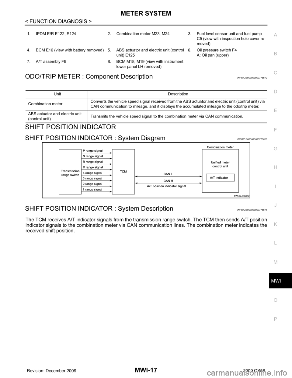
SHIFT POSITION INDICATOR : System DescriptionINFOID:0000000003776614
The TCM receives A/T indicator signals from the tr ansmission range switch. The TCM then sends A/T position
indicator signals to the combination meter via CAN co mmunication lines. The combination meter indicates the
received shift position.
1. IPDM E/R E122, E124 2. Combination meter M23, M24 3. Fuel level sensor unit and fuel pump
C5 (view with inspection hole cover re-
moved)
4. ECM E16 (view with battery removed) 5. ABS actuator and electric unit (control unit) E1256. Oil pressure switch F4
A: Oil pan (upper)
7. A/T assembly F9 8. BCM M18, M19 (view with instrument
lower panel LH removed)
Unit Description
Combination meter Converts the vehicle speed signal
received from the ABS actuator and electric unit (control unit) via
CAN communication to mileage, and it displays the accumulated mileage to the odo/trip meter.
ABS actuator and electric unit
(control unit) Transmits the vehicle speed signal to the combination meter via CAN communication.
AWNIA1906GB
Revision: December 20092009 QX56
Page 2740 of 4171
MWI-18
< FUNCTION DIAGNOSIS >
METER SYSTEM
SHIFT POSITION INDICATOR : Component Parts Location
INFOID:0000000003776615
SHIFT POSITION INDICATOR : Component DescriptionINFOID:0000000003776616
WARNING LAMPS/INDICATOR LAMPS
WARNING LAMPS/INDICATOR LAMPS : System DiagramINFOID:0000000003776617
1. IPDM E/R E122, E124 2. Combination meter M23, M24 3. Fuel level sensor unit and fuel pump
C5 (view with inspection hole cover re-
moved)
4. ECM E16 (view with battery removed) 5. ABS actuator and electric unit (control
unit) E125 6. Oil pressure switch F4
A: Oil pan (upper)
7. A/T assembly F9 8. BCM M18, M19 (view with instrument
lower panel LH removed)
AWNIA0201ZZ
Unit Description
Combination meter Displays the shift position on the information display using shift position signal received from TCM.
TCM Transmits the shift position signal to the combination meter via CAN communication.
JSNIA0449GB
Revision: December 20092009 QX56
Page 2741 of 4171
MWI
METER SYSTEMMWI-19
< FUNCTION DIAGNOSIS >
C
DE
F
G H
I
J
K L
M B A
O P
WARNING LAMPS/INDICATOR LAMPS : System DescriptionINFOID:0000000003776618
OIL PRESSURE WARNING LAMP
• IPDM E/R reads the ON/OFF signals from the oil pressure switch and transmits the oil pressure switch sig-
nal to the combination meter via BCM with the CAN communication line.
• The combination meter turns the oil pressure warning lamp ON/OFF according to the oil pressure switch sig- nal received via CAN communication.
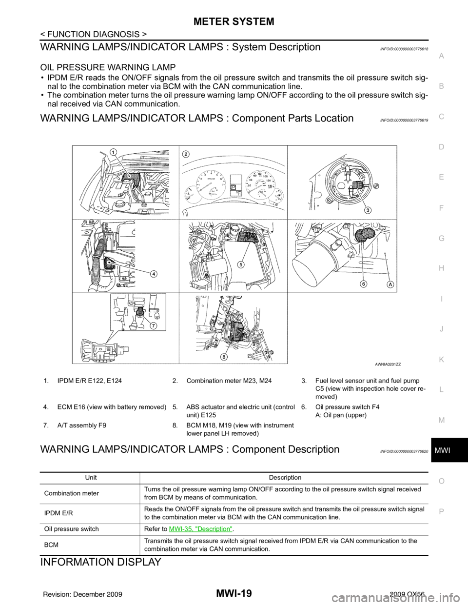
WARNING LAMPS/INDICATOR LAMPS : Component Parts LocationINFOID:0000000003776619
WARNING LAMPS/INDICATOR LAMPS : Component DescriptionINFOID:0000000003776620
INFORMATION DISPLAY
1. IPDM E/R E122, E124 2. Combination meter M23, M24 3. Fuel level sensor unit and fuel pump
C5 (view with inspection hole cover re-
moved)
4. ECM E16 (view with battery removed) 5. ABS actuator and electric unit (control unit) E1256. Oil pressure switch F4
A: Oil pan (upper)
7. A/T assembly F9 8. BCM M18, M19 (view with instrument
lower panel LH removed)
AWNIA0201ZZ
Unit Description
Combination meter Turns the oil pressure warning lamp ON/OFF according to the oil pressure switch signal received
from BCM by means of communication.
IPDM E/R Reads the ON/OFF signals from the oil pressure switch and transmits the oil pressure switch signal
to the combination meter via BCM with the CAN communication line.
Oil pressure switch Refer to MWI-35, "
Description".
BCM Transmits the oil pressure switch signal received from IPDM E/R via CAN communication to the
combination meter via CAN communication.
Revision: December 20092009 QX56
Page 2742 of 4171
MWI-20
< FUNCTION DIAGNOSIS >
METER SYSTEM
INFORMATION DISPLAY : System Diagram
INFOID:0000000003776621
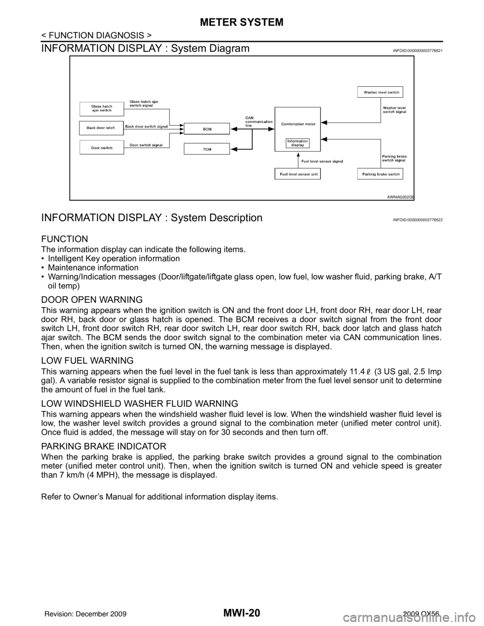
INFORMATION DISPLAY : System DescriptionINFOID:0000000003776622
FUNCTION
The information display can indicate the following items.
• Intelligent Key operation information
• Maintenance information
• Warning/Indication messages (Door/liftgate/liftgate glass open, low fuel, low washer fluid, parking brake, A/T
oil temp)
DOOR OPEN WARNING
This warning appears when the ignition switch is ON and the front door LH, front door RH, rear door LH, rear
door RH, back door or glass hatch is opened. The BCM receives a door switch signal from the front door
switch LH, front door switch RH, rear door switch LH, rear door switch RH, back door latch and glass hatch
ajar switch. The BCM sends the door switch signal to the combination meter via CAN communication lines.
Then, when the ignition switch is turned ON, the warning message is displayed.
LOW FUEL WARNING
This warning appears when the fuel level in the fuel tank is less than approximately 11.4 (3 US gal, 2.5 Imp
gal). A variable resistor signal is supplied to the combination meter from the fuel level sensor unit to determine
the amount of fuel in the fuel tank.
LOW WINDSHIELD WASHER FLUID WARNING
This warning appears when the windshield washer fluid level is low. When the windshield washer fluid level is
low, the washer level switch provides a ground signal to the combination meter (unified meter control unit).
Once fluid is added, the message will stay on for 30 seconds and then turn off.
PARKING BRAKE INDICATOR
When the parking brake is applied, the parking brake switch provides a ground signal to the combination
meter (unified meter control unit). Then, when the igni tion switch is turned ON and vehicle speed is greater
than 7 km/h (4 MPH), the message is displayed.
Refer to Owner’s Manual for additional information display items.
AWNIA0202GB
Revision: December 20092009 QX56
Page 2743 of 4171
MWI
METER SYSTEMMWI-21
< FUNCTION DIAGNOSIS >
C
DE
F
G H
I
J
K L
M B A
O P
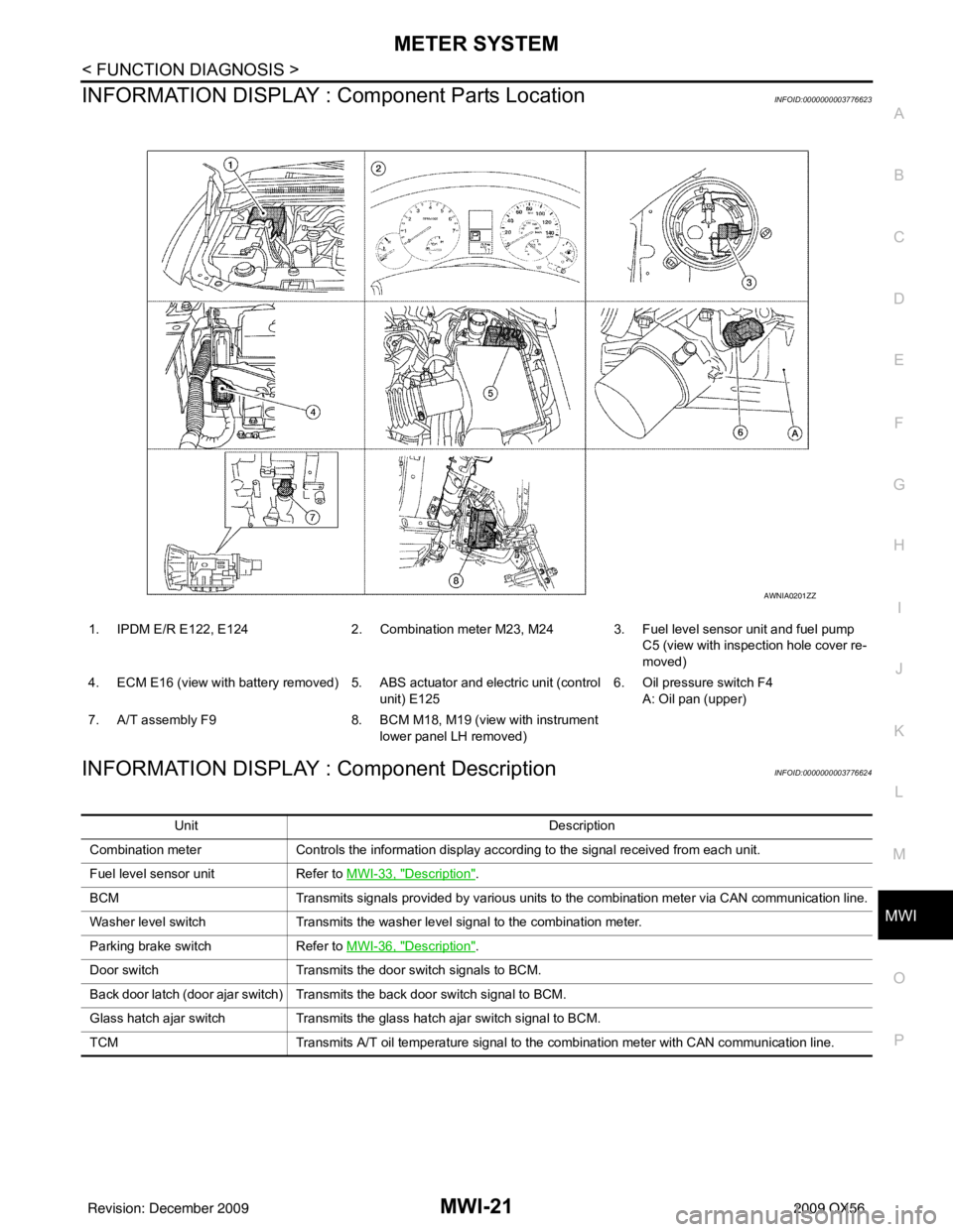
INFORMATION DISPLAY : Co mponent Parts LocationINFOID:0000000003776623
INFORMATION DISPLAY : Component DescriptionINFOID:0000000003776624
1. IPDM E/R E122, E124 2. Combination meter M23, M24 3. Fuel level sensor unit and fuel pump
C5 (view with inspection hole cover re-
moved)
4. ECM E16 (view with battery removed) 5. ABS actuator and electric unit (control unit) E1256. Oil pressure switch F4
A: Oil pan (upper)
7. A/T assembly F9 8. BCM M18, M19 (view with instrument
lower panel LH removed)
AWNIA0201ZZ
Unit Description
Combination meter Controls the information display according to the signal received from each unit.
Fuel level sensor unit Refer to MWI-33, "
Description".
BCM Transmits signals provided by various units to the combination meter via CAN communication line.
Washer level switch Transmits the washer level signal to the combination meter.
Parking brake switch Refer to MWI-36, "
Description".
Door switch Transmits the door switch signals to BCM.
Back door latch (door ajar switch) Transmits the back door switch signal to BCM.
Glass hatch ajar switch Transmits the glass hatch ajar switch signal to BCM.
TCM Transmits A/T oil temperature signal to the combination meter with CAN communication line.
Revision: December 20092009 QX56
Page 2744 of 4171
MWI-22
< FUNCTION DIAGNOSIS >
COMPASS
COMPASS
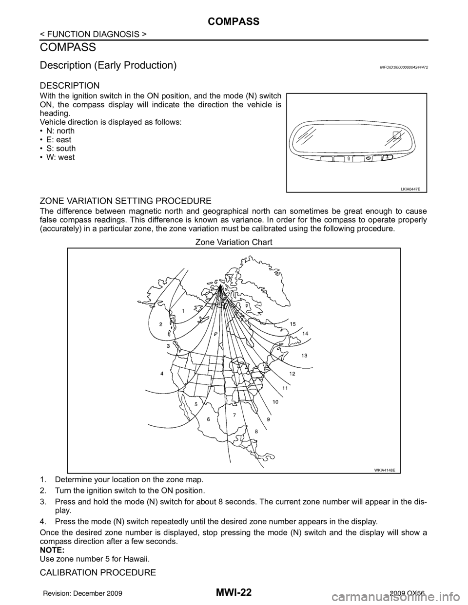
Description (Early Production)INFOID:0000000004244472
DESCRIPTION
With the ignition switch in the ON position, and the mode (N) switch
ON, the compass display will indicate the direction the vehicle is
heading.
Vehicle direction is displayed as follows:
• N: north
• E: east
• S: south
•W: west
ZONE VARIATION SETTING PROCEDURE
The difference between magnetic north and geographical north can sometimes be great enough to cause
false compass readings. This difference is known as variance. In order for the compass to operate properly
(accurately) in a particular zone, the zone variation must be calibra ted using the following procedure.
Zone Variation Chart
1. Determine your location on the zone map.
2. Turn the ignition switch to the ON position.
3. Press and hold the mode (N) switch for about 8 sec onds. The current zone number will appear in the dis-
play.
4. Press the mode (N) switch repeatedly until the desired zone number appears in the display.
Once the desired zone number is displayed, stop pre ssing the mode (N) switch and the display will show a
compass direction after a few seconds.
NOTE:
Use zone number 5 for Hawaii.
CALIBRATION PROCEDURE
LKIA0447E
WKIA4148E
Revision: December 20092009 QX56
Page 2745 of 4171
MWI
COMPASSMWI-23
< FUNCTION DIAGNOSIS >
C
DE
F
G H
I
J
K L
M B A
O P
The compass display is equipped with an automatic correc tion function. If the compass display reads “CAL” or
the direction is not shown correctly, perform the correction procedure below.
1. Press and hold the mode (N) switch for about 10 seconds. The display will read “CAL”.
2. Drive the vehicle slowly in a circle, in an open, safe place. The initial calibration is completed in about 1.5 turns.
NOTE:
In places where the terrestrial m agnetism is extremely disturbed, the
initial correction may start automatically.
LKIA0447E
Revision: December 20092009 QX56