Page 2512 of 4171

INL-68
< ECU DIAGNOSIS >
BCM (BODY CONTROL MODULE)
DTC Inspection Priority Chart
INFOID:0000000004109556
If some DTCs are displayed at the same time, perform inspections one by one based on the following priority
chart.
DTC IndexINFOID:0000000004109557
NOTE: Details of time display
• CRNT: Displays when there is a malfunction now or after returning to the normal condition until turning igni-
tion switch OFF → ON again.
• 1 - 39: Displayed if any previous malfunction is present when current condition is normal. It increases like 1
→ 2 → 3...38 → 39 after returning to the normal condition whenever ignition switch OFF → ON. The counter
remains at 39 even if the number of cycles exceeds it. It is counted from 1 again when turning ignition switch
OFF → ON after returning to the normal condition if the malfunction is detected again.
Display contents of CONS ULTFail-safe Cancellation
U1000: CAN COMM CIRCUIT I nhibit engine crankingWhen the BCM re-establishes communication with the other mod-
ules.
U1010: CONTROL UNIT (CAN) Inhibit engine cranking When the BCM re-start communicating with the other modules.
Priority DTC
1 • U1000: CAN COMM CIRCUIT
• U1010: CONTROL UNIT (CAN)
2 • B2190: NATS ANTENNA AMP
• B2191: DIFFERENCE OF KEY
• B2192: ID DISCORD BCM-ECM
• B2193: CHAIN OF BCM-ECM
• B2013: STRG COMM 1
• B2552: INTELLIGENT KEY
• B2590: NATS MALFUNCTION
3 • C1729: VHCL SPEED SIG ERR
• C1735: IGNITION SIGNAL
4 • C1704: LOW PRESSURE FL
• C1705: LOW PRESSURE FR
• C1706: LOW PRESSURE RR
• C1707: LOW PRESSURE RL
• C1708: [NO DATA] FL
• C1709: [NO DATA] FR
• C1710: [NO DATA] RR
• C1711: [NO DATA] RL
• C1712: [CHECKSUM ERR] FL
• C1713: [CHECKSUM ERR] FR
• C1714: [CHECKSUM ERR] RR
• C1715: [CHECKSUM ERR] RL
• C1716: [PRESSDATA ERR] FL
• C1717: [PRESSDATA ERR] FR
• C1718: [PRESSDATA ERR] RR
• C1719: [PRESSDATA ERR] RL
• C1720: [CODE ERR] FL
• C1721: [CODE ERR] FR
• C1722: [CODE ERR] RR
• C1723: [CODE ERR] RL
• C1724: [BATT VOLT LOW] FL
• C1725: [BATT VOLT LOW] FR
• C1726: [BATT VOLT LOW] RR
• C1727: [BATT VOLT LOW] RL
Revision: December 20092009 QX56
Page 2513 of 4171

BCM (BODY CONTROL MODULE)INL-69
< ECU DIAGNOSIS >
C
DE
F
G H
I
J
K
M A
B
INL
N
O P
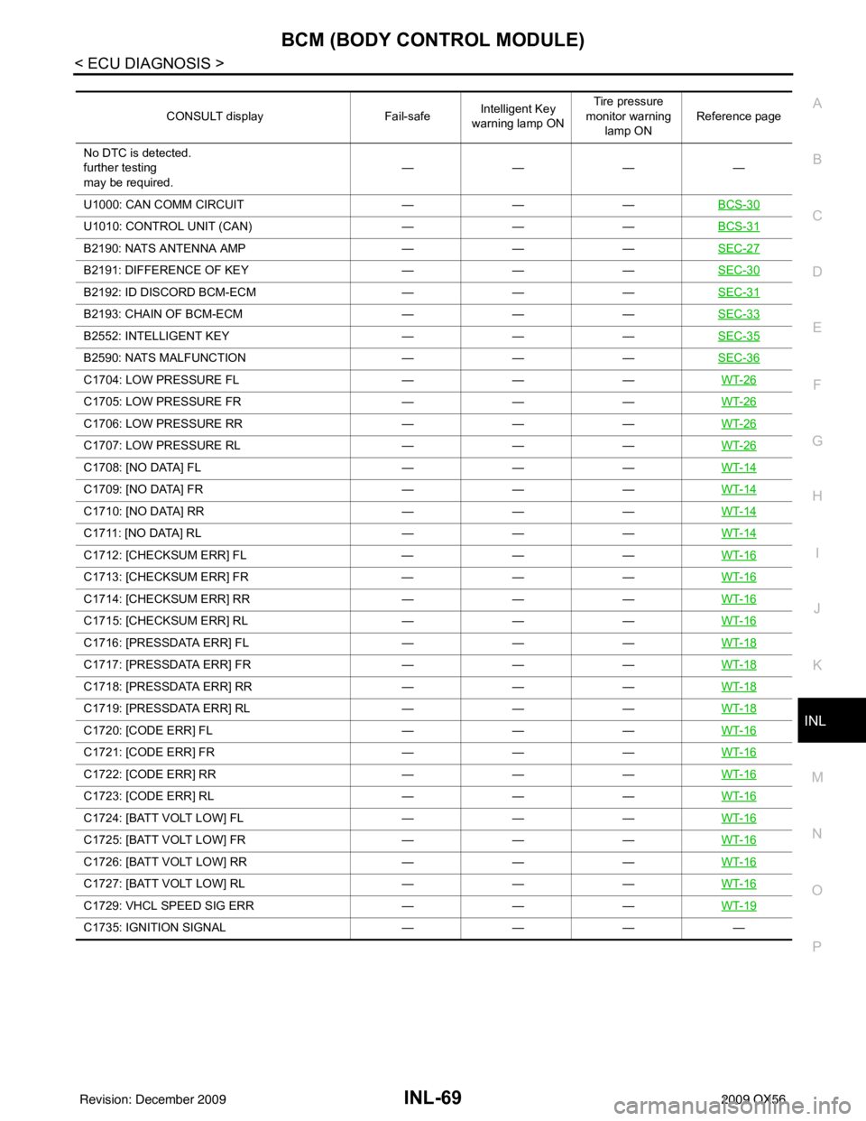
CONSULT display Fail-safeIntelligent Key
warning lamp ON Tire pressure
monitor warning lamp ON Reference page
No DTC is detected.
further testing
may be required. ————
U1000: CAN COMM CIRCUIT ———BCS-30
U1010: CONTROL UNIT (CAN) ———BCS-31
B2190: NATS ANTENNA AMP ———SEC-27
B2191: DIFFERENCE OF KEY ———SEC-30
B2192: ID DISCORD BCM-ECM ———SEC-31
B2193: CHAIN OF BCM-ECM ———SEC-33
B2552: INTELLIGENT KEY ———SEC-35
B2590: NATS MALFUNCTION ———SEC-36
C1704: LOW PRESSURE FL ———WT-26
C1705: LOW PRESSURE FR ———WT-26
C1706: LOW PRESSURE RR ———WT-26
C1707: LOW PRESSURE RL ———WT-26
C1708: [NO DATA] FL ———WT-14
C1709: [NO DATA] FR ———WT-14
C1710: [NO DATA] RR ———WT-14
C1711: [NO DATA] RL ———WT-14
C1712: [CHECKSUM ERR] FL ———WT-16
C1713: [CHECKSUM ERR] FR ———WT-16
C1714: [CHECKSUM ERR] RR ———WT-16
C1715: [CHECKSUM ERR] RL ———WT-16
C1716: [PRESSDATA ERR] FL ———WT-18
C1717: [PRESSDATA ERR] FR ———WT-18
C1718: [PRESSDATA ERR] RR ———WT-18
C1719: [PRESSDATA ERR] RL ———WT-18
C1720: [CODE ERR] FL ———WT-16
C1721: [CODE ERR] FR ———WT-16
C1722: [CODE ERR] RR ———WT-16
C1723: [CODE ERR] RL ———WT-16
C1724: [BATT VOLT LOW] FL ———WT-16
C1725: [BATT VOLT LOW] FR ———WT-16
C1726: [BATT VOLT LOW] RR ———WT-16
C1727: [BATT VOLT LOW] RL ———WT-16
C1729: VHCL SPEED SIG ERR ———WT-19
C1735: IGNITION SIGNAL ——— —
Revision: December 20092009 QX56
Page 2539 of 4171

INT-16
< ON-VEHICLE REPAIR >
FLOOR TRIM
FLOOR TRIM
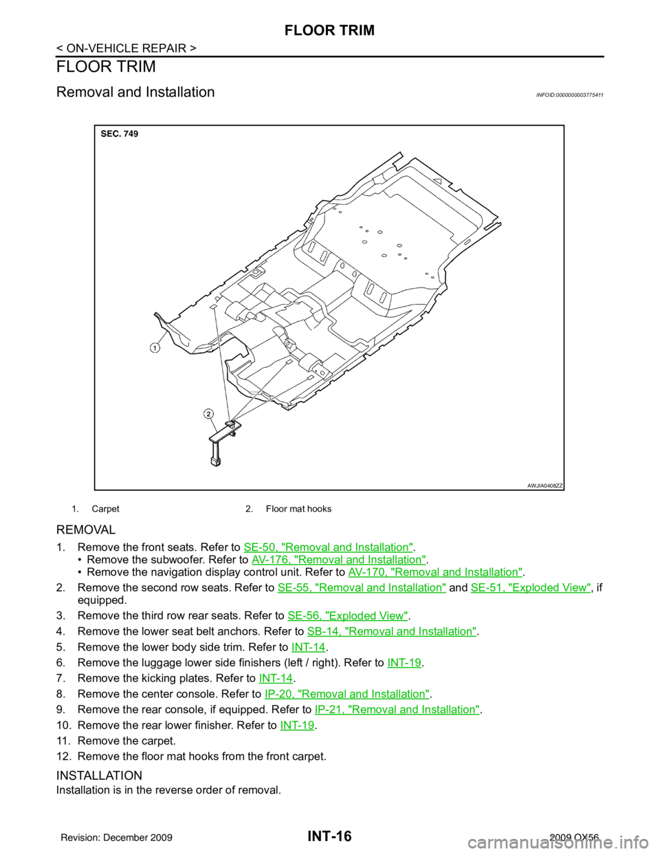
Removal and InstallationINFOID:0000000003775411
REMOVAL
1. Remove the front seats. Refer to SE-50, "Removal and Installation".
• Remove the subwoofer. Refer to AV-176, "
Removal and Installation".
• Remove the navigation display control unit. Refer to AV-170, "
Removal and Installation".
2. Remove the second row seats. Refer to SE-55, "
Removal and Installation" and SE-51, "Exploded View", if
equipped.
3. Remove the third row rear seats. Refer to SE-56, "
Exploded View".
4. Remove the lower seat belt anchors. Refer to SB-14, "
Removal and Installation".
5. Remove the lower body side trim. Refer to INT-14
.
6. Remove the luggage lower side finishers (left / right). Refer to INT-19
.
7. Remove the kicking plates. Refer to INT-14
.
8. Remove the center console. Refer to IP-20, "
Removal and Installation".
9. Remove the rear console, if equipped. Refer to IP-21, "
Removal and Installation".
10. Remove the rear lower finisher. Refer to INT-19
.
11. Remove the carpet.
12. Remove the floor mat hooks from the front carpet.
INSTALLATION
Installation is in the reverse order of removal.
1. Carpet 2. Floor mat hooks
AWJIA0408ZZ
Revision: December 20092009 QX56
Page 2541 of 4171

INT-18
< ON-VEHICLE REPAIR >
HEADLINING
CAUTION:
Disconnect both terminals from battery in advance.
REMOVAL
1. Remove the body side trim. Refer to INT-14.
2. Remove the luggage floor trim. Refer to INT-19
.
3. Remove the sunvisor assemblies.
4. Remove the sunvisor clips.
5. Remove the sunroof welt.
6. Remove the front roof console. • Disconnect the harnesses.
7. Remove the rear roof console. • Disconnect the harnesses.
8. Remove the assist grips.
9. Remove the lamp assembly and the rear roof finisher. • Disconnect the harness.
10. Remove the headlining. • Remove the clips from the rear of headlining.
• Disconnect the harnesses.
11. Remove the rear air control. • Disconnect the harness.
12. Remove the rear audio control assembly. • Disconnect the harness.
13. Remove the lamp assemblies. • Disconnect the harnesses.
14. Remove the air vents.
15. Remove the front roof console bracket.
16. Remove the rear roof console front bracket.
17. Remove the assist grip brackets from roof.
INSTALLATION
Installation is in the reverse order of removal.
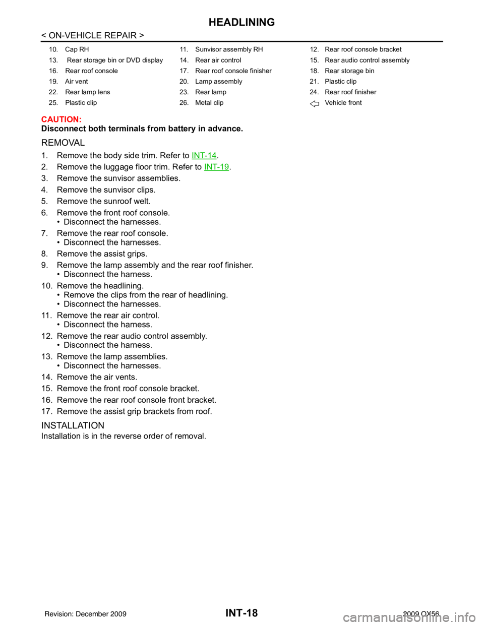
10. Cap RH 11. Sunvisor assembly RH12. Rear roof console bracket
13. Rear storage bin or DVD display 14. Rear air control 15. Rear audio control assembly
16. Rear roof console 17. Rear roof console finisher18. Rear storage bin
19. Air vent 20. Lamp assembly21. Plastic clip
22. Rear lamp lens 23. Rear lamp24. Rear roof finisher
25. Plastic clip 26. Metal clip Vehicle front
Revision: December 20092009 QX56
Page 2557 of 4171

INSTRUMENT PANEL ASSEMBLYIP-13
< ON-VEHICLE REPAIR >
C
DE
F
G H
I
K L
M A
B
IP
N
O P
Removal and InstallationINFOID:0000000003775422
REMOVAL
CAUTION:
Disconnect both the negative and positive battery terminals in advance.
1. Disconnect both negative and positive terminal s, then wait at least 3 minutes.
2. Remove front center console. Refer to IP-20, "
Removal and Installation".
3. Remove steering column assembly. Refer to ST-20, "
Removal and Installation".
4. Remove combination meter. Refer to MWI-102, "
Removal and Installation".
5. Remove instrument panel upper cover and disconnect rear sonar speaker (if equipped).
6. Remove cluster lid C. Refer to IP-16, "
Removal and Installation".
7. Remove display assembly. Refer to AV-168, "
Removal and Installation".
8. Remove instrument lower/upper panel RH and glove box. Refer to IP-17, "
Removal and Installation" and
IP-18, "
Removal and Installation".
9. Release the clips, disconnect the optical sensor harness and remove defroster grille.
10. Release the clips, disconnect the connectors and remove RH, LH, and center speakers.
11. Remove RH/LH front pillar finishers. Refer to INT-14, "
Removal and Installation".
12. Remove the passenger air bag module nuts and disconnect the connectors. Refer to SR-10, "
Removal
and Installation".
13. Disconnect remaining optional equipment connectors (if equipped).
14. Remove instrument panel and pad assembly screws.
15. Release instrument panel and pad assembly lifting rearward away from steering member, then carefully remove through front door opening.
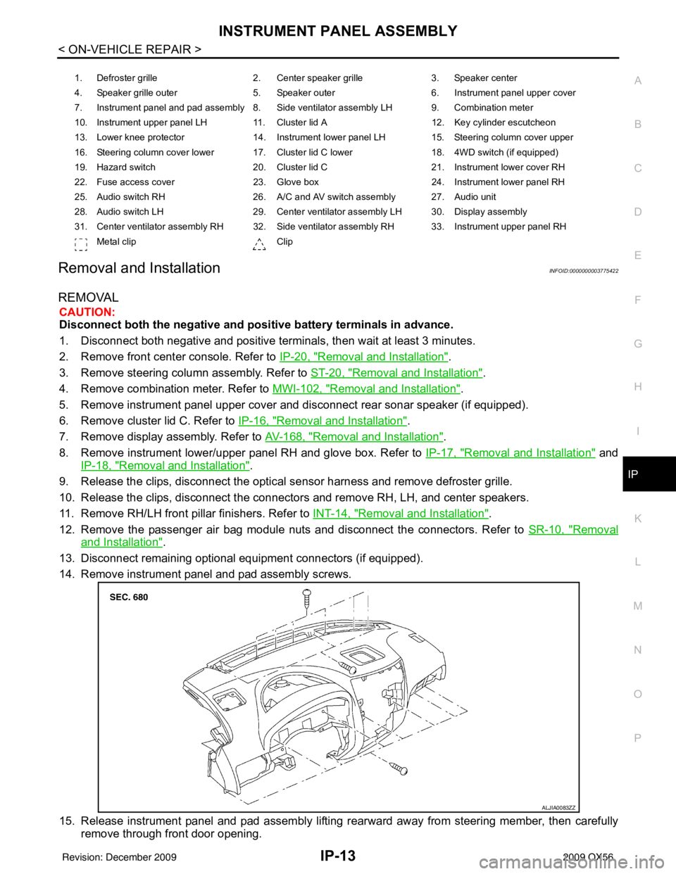
1. Defroster grille 2. Center speaker grille3. Speaker center
4. Speaker grille outer 5. Speaker outer6. Instrument panel upper cover
7. Instrument panel and pad assembly 8. Side ventilator assembly LH 9. Combination meter
10. Instrument upper panel LH 11. Cluster lid A 12. Key cylinder escutcheon
13. Lower knee protector 14. Instrument lower panel LH 15. Steering column cover upper
16. Steering column cover lower 17. Cluster lid C lower 18. 4WD switch (if equipped)
19. Hazard switch 20. Cluster lid C21. Instrument lower cover RH
22. Fuse access cover 23. Glove box 24. Instrument lower panel RH
25. Audio switch RH 26. A/C and AV switch assembly 27. Audio unit
28. Audio switch LH 29. Center ventilator assembly LH 30. Display assembly
31. Center ventilator assembly RH 32. Side ventilator assembly RH 33. Instrument upper panel RH Metal clip Clip
ALJIA0083ZZ
Revision: December 20092009 QX56
Page 2577 of 4171
![INFINITI QX56 2009 Factory Service Manual LAN-8
< FUNCTION DIAGNOSIS >[CAN FUNDAMENTAL]
TROUBLE DIAGNOSIS
Example: Data link connector branch line open circuit
NOTE:
• When data link connector branch line is open, transmission and reception INFINITI QX56 2009 Factory Service Manual LAN-8
< FUNCTION DIAGNOSIS >[CAN FUNDAMENTAL]
TROUBLE DIAGNOSIS
Example: Data link connector branch line open circuit
NOTE:
• When data link connector branch line is open, transmission and reception](/manual-img/42/57031/w960_57031-2576.png)
LAN-8
< FUNCTION DIAGNOSIS >[CAN FUNDAMENTAL]
TROUBLE DIAGNOSIS
Example: Data link connector branch line open circuit
NOTE:
• When data link connector branch line is open, transmission and reception of CAN communication signals
are not affected. Therefore, no symptoms occur. However, be sure to repair malfunctioning circuit.
• When data link connector branch line is open, “ECU list” displayed on the CONSULT-III “CAN DIAG SUP- PORT MNTR” may be the same as when the CAN communication line has short-circuit. However, symp-
toms differ depending on the case. See below chart for the differences.
EPS control unit Normal operation.
Combination meter • Shift position indicator and OD OFF indicator turn OFF.
• Warning lamps turn ON.
ABS actuator and electric unit (control unit) Normal operation.
TCM No impact on operation.
IPDM E/R Normal operation.
Unit name
Symptom
SKIB8739E
Unit nameSymptom
ECM
Normal operation.
BCM
EPS control unit
Combination meter
ABS actuator and electric unit (control unit)
TCM
IPDM E/R
“ECU list” on the “CAN DIAG SUPPORT MNTR”(CONSULT-III) Difference of symptom
Data link connector branch line open circuit All Diag on CAN units are not
indicated.Normal operation.
CAN-H, CAN-L harness short-circuit Most of the units which are connected to the CAN
communication system enter fail-safe mode or are
deactivated.
Revision: December 20092009 QX56
Page 2581 of 4171
LAN-12
< FUNCTION DIAGNOSIS >[CAN FUNDAMENTAL]
TROUBLE DIAGNOSIS
Example: Vehicle Display
ItemResult indi-
cated Error counter
Description
CAN_COMM
(Initial diagnosis) OK
0 Normal at present
NG 1 – 50 Control unit error
(The number indicates how many times diagnosis has been
run.)
CAN_CIRC_1
(Transmission diagnosis) OK
0 Normal at present
UNKWN 1 – 50 Unable to transmit for 2 seconds or more at present.
(The number indicates how many times diagnosis has been
run.)
CAN_CIRC_2 – 9
(Reception diagnosis of each unit) OK
0 Normal at present
UNKWN 1 – 50 Unable to transmit for 2 seconds or more at present.
(The number indicates how many times diagnosis has been
run.)
Diagnosis not performed.
No control unit for receiving signals. (No applicable optional
parts)
Revision: December 20092009 QX56
Page 2588 of 4171
LAN
DIAGNOSIS AND REPAIR WORKFLOWLAN-19
< BASIC INSPECTION > [CAN FUNDAMENTAL]
C
D
E
F
G H
I
J
K L
B A
O P
N
Some items may not be needed depending on CAN system type of vehicle.
Create On-board Diagnosis Copy Sheet
Display the trouble diagnosis result of CAN communica
tion with the on-board diagnosis function on the vehicle
monitor, etc. Copy them on the on-board diagnosis copy sheet.
NOTE:
PKID1212E
Revision: December 20092009 QX56